カテゴリー
category_usa

PCB Design

What Is PCB Design?

PCB design is the design of a Printed Circuit Board (PCB).

A printed circuit board is a so-called patterned circuit board in which copper is applied to a PCB board made of materials such as glass, fiber, or paper phenol, and then etched using a solvent known as etching, leaving only the copper foil for the circuit portions.

In other words, PCB design is the detailed design of patterns and layer configurations on PCB boards, along with chip components such as ICs and LCRs to be placed, using dedicated circuit diagrams, simulators, wiring layouts, and CAD tools for electromagnetic field, heat generation, and stress analysis.

Uses of PCB Designs

The ultimate purpose of PCB designs is to be used in practical applications in the form of PCBs, which are used inside electrical appliances such as air conditioners, refrigerators, and televisions. The tools used to materialize the PCB as an electronic circuit board to be built into the product are dedicated schematic CAD and board pattern design CAD.

The PCB design procedure generally consists of designing an electronic circuit, converting the circuit into an actual parts list, and then creating a copper foil pattern circuit on the board in the form of a pattern that represents the circuit and mounted parts.

Principles of PCB Designs

To explain the principle of PCB designs, it is necessary to understand it from the principle of PCB, which, as mentioned above, refers to printed circuit boards, which are made of insulators such as glass, fiber, or paper that do not conduct electricity. The PCB is the result of etching the copper foil except for the areas that are to be electrically conductive.

The pattern design information necessary to form the pattern circuit on the PCB is the PCB design itself, which is the embodiment of how the circuit will be realized on the PCB. The pattern design information is the electronic circuit to realize the necessary functions of the product at the first stage, as described in the usage of the product as the main source of information.

Without this circuit diagram, nothing can begin. After the circuit diagram and mounted components such as ICs and chip components are created and registered in CAD, the circuit diagram information is then dropped into a dedicated board pattern design CAD system. This work is usually handled by staff dedicated to pattern design or by an outsourcing company.

The circuit designer is in charge of inputting the necessary information, and the minimum information required at that time is the board dimensions, hole diameters, board, and copper foil thicknesses, and the placement of mounted components, which must be specified in advance. 

カテゴリー
category_usa

Spectrum Analyzers

What is a Spectrum Analyzer?

A spectrum analyzer is a type of electrical measuring instrument.

The spectrum analyzer screen displays frequency on the horizontal axis and amplitude on the vertical axis, representing frequency as a component.

There are two types, one for high-frequency and the other for low-frequency, and each has different applications. The high-frequency version is mainly used to “display the distribution of frequency components” and “analyze the components of AC power” of the high-frequency signals of radio waves. In contrast, the low-frequency version is used for “noise analysis” and the like.

Since inaccurate results may be caused by static electricity, excessive power signals, etc., we recommend carefully checking the usage and conditions before use.

Uses of Spectrum Analyzers

High-frequency spectrum analyzers are used for inspection, measurement, design, repair, transmission wave, and the spurious measurement of radio equipment, transmitter, and receiver. Various setting items are important, so appropriate values must be entered according to the application.

For low-frequency applications, some products are small and portable and are widely used in field tests for field strength measurement, frequency identification, noise measurement, machine diagnosis, structural analysis, and vibration testing. in wireless run installation work.

Spectrum analyzers are sometimes compared and described with oscilloscopes. Typically, oscilloscopes are used with spectrum analyzers, which can capture and observe signals in terms of frequency, since they are often used to observe the time axis in the lower frequency range. oscilloscopes and spectrum analyzers observe signals from different angles and have different areas of expertise, so the necessary information should be considered before use.

Principle of Spectrum Analyzers

Heterodyne describes a signal processing technique and refers to the signal frequency created by converting the difference in frequencies generated by mixing or combining other frequencies with the received radio wave.

Superheterodyne generally refers to a reception method that converts the received signal into a fixed intermediate frequency (IF) that is easier to process than the original carrier wave. method are sometimes collectively referred to as superheterodyne.

In the superheterodyne-tuned sweep method, the input signal is passed through an attenuator and a low-pass filter while being limited by them. sweeps and measures the band-limited frequency with the frequency resolution set by the band-pass filter.

The FFT method has become popular in recent years due to its development. It is the same as the superheterodyne tuned sweep method up to the point where the input signal is frequency converted. In some cases, the output of the bandpass filter is converted to a digital signal by an AD converter and then the frequency is displayed by a fast Fourier transform. Since the time to measurement can be shortened, this method is suitable for measurement when the spectrum changes quickly.

カテゴリー
category_usa

Microswitches

What Is a Microwave Switch?

Microwave Switches

Microwave Switches are components that detect the position of an object and provide a contact output. They are mainly used as switches for detection, but may also be used for operation.

The contact output of Microwave Switch is incorporated into a control circuit to operate or stop a machine. Microwave Switch contacts themselves generally have an allowable current of about several amperes. The part that comes in contact with an object has an actuator, which can be a button, roller, or lever type.

Uses of Microwave Switch

Microwave Switches have a snap-action mechanism and are characterized by their high accuracy in detecting position.

They are used in door interlocks, safety switches for vending machines, microwave ovens, elevators, and industrial equipment. They are also used in sensors that detect the opening and closing of printers and other equipment.

Sizes are classified into four types, from general type to ultra-miniature, and are available in reverse action type for locations subject to severe vibration or shock, magnetic quenching type for applications requiring stable operation of DC circuits, and immersion-proof type for high sealing performance. They have a wide range of applications from industrial equipment to home appliances.

Principle of Microwave Switch

Microwave Switch is divided into five parts, and the movement of the actuator leads up to the contact point.

1. Actuator Part

External force or motion is transmitted to the internal mechanism. The actuator is connected to the snap-action mechanism, which can be a button, roller, or lever type.

2. Snap Action Mechanism

It consists of parts such as a spring, a movable piece, a common terminal, and a receiver. When the force applied from the actuator increases, the movable piece and spring move the contacts.

3. Contact Point

There are two types of contacts: normally open and normally closed. Generally, each Microwave Switch has one of these contacts, but some have only one. There are crossbar type and rivet type contacts, and they are used according to the voltage and current of the circuit. Gold, silver, or plating is used as the material.

4. Terminal

Terminals connect the switch to the circuit. Terminals are available in soldering, connector, screw-tightening, and printed circuit board types, and the connection method is selected according to the application.

5. Case

The case protects the circuit and mechanism, and the resin is selected according to the required mechanical strength and heat resistance.

Uses of Microwave Switch

1. Doors and Printer Open/Close Covers

Microwave Switches are used to detect the position of doors and covers. Microwave Switches with actuators that have a wide range of shapes are used. Microwave Switch can be installed in a limited space.

2. Detecting the Opening and Closing of Dishwasher Covers and Washing Machine Lids

Microwave Switches are used to detect the position of covers and lids. These devices may be exposed to water, so Microwave Switches are waterproofed.

3. Mouse Operation Input

This is used in a mouse not as a position detection switch but as an operation switch. Microwave Switch detects mouse clicks and outputs them to the computer.

Other Information on Microwave Switch

1. The Difference Between Microwave Switch and Limit Switch

Microwave Switches and Limit Switches are often confused with each other. Limit switches, like Microwave Switches, are used as detection switches, but there are differences in construction and application. Limit switches consist of a built-in Microwave Switch in a plastic or metal case.

Limit switches are used to improve weather resistance when exposed to rainwater. Limit switches are also used in some industrial facilities as a measure against dust and oil.

2. Snap-Action Mechanism of Microwave Switch

A snap-action mechanism is a mechanism that quickly switches the movable contacts regardless of the speed at which the switch is operated. In contrast, a mechanism in which the operating speed is the moving speed of the movable contacts is called a slow-action mechanism.

Microwave Switches with snap-action mechanisms are characterized by a fast switching speed of the contacts, which minimizes arcing between the contacts. Even small Microwave Switches can have long contact life and excellent durability.

カテゴリー
category_usa

Electrostatic Instrument

What Is an Electrostatic Instrument?

An Electrostatic Instrument is device that measures the voltage of static electricity generated on the surface of an object.

This instrument is equipped with a surface potential sensor that enables non-contact measurement when pointed at the object being measured. Electrostatic Instruments are also called Surface Potentiometers or Electrostatic Potential Meters, and are mainly used in production processes in the manufacturing industry.

Uses of Electrostatic Instruments

Electrostatic Instruments play a crucial role in addressing issues caused by static electricity during the production process. Accurate measurement of static electricity is the first step in implementing preventive measures and evaluating their effectiveness. Depending on the process, these instruments may also be used for continuous monitoring of static electricity generation.

1. Foreign Matter Adhesion

Trouble occurs when charged foreign matter, such as dust, adheres to a charged product. For example, in the painting process, this can cause unevenness in the coating. 

2. Electrostatic Destruction (ESD Destruction)

Semiconductor components such as integrated circuits can be destroyed by electrostatic discharge.

3.Malfunction

Devices that operate with small currents and voltages, like electronic balances, weight checkers, and metal detectors, may be affected by electromagnetic noise when static electricity is discharged. 

4.Discharge to the Human Body

Electrostatic discharge from a charged object to the human body not only causes pain and discomfort to the human body, but can also cause equipment malfunction and ignition of combustible materials.

Principle of Electrostatic Instrument

When the surface of an object is charged and static electricity is generated, an electric field is generated around the object. Electrostatic Instruments measure the strength of this electric field and calculate the electrostatic voltage. The principle of a typical Electrostatic Instrument, such as Surface Potentiometer, is as follows:

The surface potential sensor uses the electrostatic induction phenomenon. When the sensing electrode receives an electrostatic field intensity Eo (proportional to the charging voltage Vo) from a charged object, an induced charge q is accumulated on the surface of the sensing electrode. When a shield plate of a size that covers the entire detection electrode is placed between the detection electrode and the object and rotated at a constant speed, the induced charge q accumulated on the detection electrode is discharged at the moment the shield plate covers it, and when the shield plate passes by, the induced charge q is accumulated again. This periodic movement of charge q, that is, the magnitude of the alternating current Is, depends on the electric field strength, so the charging voltage Vo of the object surface can be obtained by measuring the current Is.

However, in the this measurement method, the measured value depends greatly on the distance between the surface potential sensor and the object to be measured. The further away the object is from the sensor, the weaker the electric field becomes, so it is inevitable that the measured value will appear smaller. Therefore, it is necessary to keep the distance between the surface potential sensor and the object to be measured at the specified distance.

To address this distance-dependent measurement issue, another device is the voltage feedback-type surface potential meter. In this system, a high-voltage power supply is connected to the sensing electrode, and the voltage output of the high-voltage power supply is adjusted so that the alternating current Is becomes zero. Since the current Is stops flowing when the voltage of the object to be measured and the voltage of the sensor are the same, the output voltage of the high-voltage power supply at that time can be said to be equal to the charged voltage of the object to be measured.

How to Use Electrostatic Instruments

To measure the electrostatic charge of a charged object with a typical Electrostatic Instrument, the procedure is as follows:

1. Place the surface potential sensor at the distance specified by Electrostatic Instrument, with the detection electrode of the surface potential sensor parallel to the surface to be measured.

2. Set the measuring range higher than the expected voltage and start measurement. When a rough measurement value is obtained, adjust the measuring range and adopt the measured value.

When measuring with a voltage feedback type surface potential meter, the detection electrode of the surface potential sensor is placed parallel to the surface of the object to be measured, but the distance from the object does not need to be strictly defined. The voltage of the high-voltage power supply is gradually increased to find the point where the alternating current flowing to the detection electrode becomes zero. The output voltage of the high-voltage power supply at that point becomes the charged voltage of the object to be measured, and the unit of measurement value is V or KV. It is important to select an appropriate instrument based on the assumption of the maximum static electricity voltage.

Other Information on Electrostatic Instruments

Causes and Prevention of Static Electricity

The following mechanisms are known to generate static electricity:

1. Peeling Charge

This occurs when overlapping materials are peeled off, such as when a protective film is pulled off a plastic sheet.

2. Friction Charging

Occurs when objects rub against each other, such as when mixing things, taking off clothes, or when motors rotate.

3. Other Charging

Electrostatic Instrument is used to measure the electrostatic charge of objects exposed to such conditions, such as grinding and powder charging. In particular, semiconductor components are highly likely to fail due to Electrostatic Instrument discharge, so it is necessary to check the inside of the process with Electrostatic Instrument on a regular basis.

The following are specific examples of measurement targets in the production process:

  1. Trays containing semiconductors, other electronic components, and their parts, their protective films, and storage shelves.
  2. Work clothes, work shoes, work process desks, chairs, and floor surfaces.
  3. Grounding bands and grounding attachments.
  4. Manufacturing equipment, such as production equipment, inspection equipment, jigs and tools, soldering irons, etc.
  5. Work standards and their protective plastic cases.
  6. Display parts of monitors.
  7. Various types of purchased films.

When the generation of static electricity is unavoidable, ionizers and other static eliminators are installed to actively eliminate static electricity, but measurement using Electrostatic Instruments is essential to ensure the effectiveness of such measures.

Spark Killers

What Is a Spark Killer?

A spark killer is a device that suppresses sparks.

*Spark: A phenomenon in which a spark occurs when electricity flows in the air between two points that are not in contact with each other due to a potential difference in a switch, etc.

When a spark occurs, semiconductor elements and transistors in the circuit may be damaged, so it is necessary to have spark killers and other spark prevention measures in the circuit, especially when switches are used in DC current circuits.

Uses of Spark Killers

Spark killers are widely used in electrical equipment that operates on DC current. Especially when DC current is used as a power source, it is recommended to consider installing a spark killer because of the possibility of sparks around the switch.

Since spark killers have precisely determined the rated voltage, resistance, capacitance, and proper temperature for use, they should be selected appropriately in consideration of these factors.

If the spark killer cannot withstand the voltage in the operating environment, it may cause accidents.

Principle of Spark Killers

A spark killer consists of a resistor and a film capacitor connected in series. In a circuit consisting of a power supply, a switch, and a resistor, there are two basic ways to install a spark killer circuit: either place it in parallel with the switch or place it in parallel with the resistor.

When arranged in parallel with the switch, when the switch is off, the circuits are connected through the spark killer so that no large potential difference is created at the switch. When arranged in parallel with a resistor, one side of the switch will be at a high voltage when the switch is turned off, and sparks are likely to occur. Therefore, a spark killer prevents the high voltage from occurring, thus making it less likely to cause a spark.

The film capacitor to be used should have a large enough capacitance to prevent the voltage from becoming too high when in use. For resistors, resistors with sufficient surge immunity should be selected.

gyro sensor

What Is a Gyroscopic (Gyro) Sensor?

Gyroscopic (Gyro) SensorsA gyroscopic (gyro) sensor is a sensor used to detect angular velocity.

It is also called a gyroscope. Angular velocity refers to the physical quantity of rotation of an object per unit of time, and is an indispensable sensor in today’s industrial machinery products, where advanced and accurate control is required.

Gyro sensors are heavily used in fields such as robotics, aircraft, and automobile body control, where feedback control must take into account minute rotations.

Uses of Gyroscopic Sensors

Gyro sensors are used in a wide range of applications in the control of smartphones, digital cameras, gaming devices, space industry, aviation, automobiles, and industrial robots.

Specific applications of gyro sensors are as follows:

  • Image stabilization of smartphones and digital cameras
  • Walking control of biped robots
  • Measurement and control of aircraft position
  • Measurement of user movement and position in VR games

Gyro sensors have different characteristics depending on the product, such as size and heat and vibration tolerance. Therefore, the accuracy of the control of the device using the gyro sensor and the environment in which it will be used must be taken into consideration when selecting a gyro sensor.

Principle of Gyroscopic Sensors

Gyro sensors are typically classified into the vibration type, which functions according to the Coriolis force, and the optical type, which functions according to the Sagnac effect of light.

1. Vibrating Gyroscopic Sensor

The Coriolis force used in vibrating gyro sensors is the fictitious force acting on an object located in a rotating frame of reference with respect to an inertial frame.

Vibration gyro sensors can be further classified into piezoelectric and capacitive types.

  • Piezoelectric Method
    This method measures the voltage value generated in a rotating transducer as a physical quantity corresponding to the Coriolis force.
  • Capacitance Method
    The Coriolis force during rotation generates a difference in the capacitance between the left and right sensing electrodes of the resonator, and the angular velocity is calculated by measuring the Coriolis force from the difference in capacitance.

The relationship between the Coriolis force and angular velocity can be expressed by the following equation.

ω=F/2mv (ω: angular velocity, F: Coriolis force, m: mass of object, v: velocity of movement)

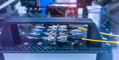
2. Optical Gyroscopic Sensor

The Sagnac effect used in optical gyroscopic sensors is the principle stating that if the optical path through which light passes is in motion, the length of the optical path will increase. This physical phenomenon occurs because the speed of light is always constant. In an optical gyroscopic sensor, the light path lengthens as the orbiting light itself rotates, and the angular velocity can be calculated by measuring the phase difference caused by the lengthening.

Other Information on Gyroscopic Sensors

1. Gyroscopic Sensor Compensation Methods

Drift Correction
There are multiple factors that can cause errors in the output of Gyroscopic (Gyro) Sensors. One of the most important such factors is drift, which refers to the drift of the zero point, which is originally given as the initial value, resulting in a gradual shift of the initial value and a larger detection error.

Internal factors that cause drift include DC component fluctuations (low-frequency fluctuations) and high-frequency noise effects; DC component fluctuations are called bias instability and high-frequency noise is called angular random walk. Bias instability depends on the stability of the supply voltage, which can be improved by reviewing the power supply.

Angular Random Walk Correction
The correction method for angular random walk is a matter of each company’s know-how, but a commonly used correction method is to use a Kalman filter.

The Kalman filter is a method for estimating the most appropriate system state based on the previous information and the currently acquired data. It can be rephrased as a problem of estimating the original state of a variable that changes with time, based on the past information and the currently acquired information. It is important to treat the measured values and the variables themselves as if they are subject to noise. 

2. Difference Between a Gyroscopic Sensor and an Accelerometer

Gyroscopic sensors are similar to accelerometers. Although they are sometimes confused, they are completely different.

As the name suggests, acceleration sensors are designed to detect acceleration. They use inertial forces to measure changes in the speed at which an object is moving and outputs them as an electrical signal. Acceleration sensors are used in a wide range of applications because other types of information, such as the state of vibration of an object and the magnitude of impact, can also be obtained from acceleration. The basic structure is similar to that of a gyro sensor.

Gyros sensors, on the other hand, as mentioned above, are used to detect angular velocity. They use the Coriolis force to measure the motion (rotation) and changes in orientation and posture of an object and output them as electrical signals. 

3. 3-, 6-, and 9-Axis Sensors

Recently, 3-axis and 6-axis sensors are often described as sensors that detect inertial force. Each corresponds to acceleration (3-axis) and angular velocity (6-axis) of forward/backward, left/right, and up/down, and as in-vehicle sensors, they are indispensable for ADAS and automatic driving technology, which are driving assistance systems for automobiles.

As an example, car navigation systems are equipped with both Gyroscopic (Gyro) Sensors and Acceleration Sensors. By using Gyroscopic (Gyro) Sensors to detect the direction of the car and Acceleration Sensors to detect the distance traveled, the current location can be displayed with high accuracy even in places where signal reception is difficult, such as inside a tunnel.

The three axes are represented by roll, pitch, and yaw, and these axes can be used to represent posture. Especially for roll and pitch, it is possible to compensate for the drift, which is a source of error, as a feedback circuit. Furthermore, as a different ref for drift correction, there is a current standard that uses a magnetometer sensor in addition to the 6-axis compatible sensor, in which case it is called a 9-axis compatible sensor.

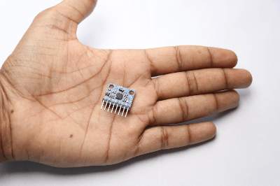
4. MEMS Compatibility With a Gyroscopic Sensor

Gyro sensors are used to display and control the motion of rotating machinery. MEMS technology is used in the semiconductor industry, where it is based on thin-film microfabrication technology.

Gyroscopic sensors also differ from optical and mechanical sensors in that they are relatively easy to miniaturize and integrate, and because MEMS sensors are highly compatible with ASICs that enable relatively sophisticated control, they are built into many devices, including smartphones and other mobile devices.

Furthermore, gyro sensors have different detection ranges for angular velocity, depending on their application. For example, mobile devices such as smartphones require a range of 300 to 2000 DPS (degrees per second, rotation angle per second), while automotive devices such as car navigation systems require a range of 100 to 500 DPS.

Therefore, when selecting a sensor, one must consider how much detection range is sufficient based on the usage conditions of the device.

カテゴリー
category_usa

Vacuum Ejector

What Is a Vacuum Ejector?

A vacuum ejector is a device that generates a vacuum by means of the Venturi effect using compressed air.

Unlike vacuum pumps and other vacuum generating devices with complex mechanical structures, vacuum ejectors are characterized by their simple design, featuring a vacuum generating structure inside the device that uses the Venturi effect. Vacuum ejectors generate the vacuum necessary for tasks like lifting parts using compressed air, which is used in production processes.

Applications of Vacuum Ejectors

Vacuum ejectors are often used in automated production lines. They are also used for dust collection and powder conveying.

1. Workpiece Suction Applications

A suction pad is attached to the vacuum line and pressed against the workpiece to create a suction. The shape and material of the suction pad must be selected according to the weight, size, and material of the workpiece.

Vacuum ejectors and suction pads are used to pick up parts and transfer workpieces. By using multiple vacuum ejectors and suction pads, the system can also be used to pick up and transfer heavy objects such as windshields in automobile production plants. 

2. Dust Collection Applications

When a vacuum ejector is used indoors, airflow to the vacuum port of the vacuum ejector is generated to suction dust and dirt from the room. Vacuum ejectors are used to clean rooms in environments where dust and dirt are undesirable, such as semiconductor and electronic component manufacturing lines and food production lines.

3. Powder Conveying Applications

The vacuum conveyor is sealed and the pressure is reduced using a vacuum ejector. When air is injected through the nozzle port, the powder or grain can be conveyed along with the airflow in the piping.

Principle of Vacuum Ejector

The structure of a vacuum ejector consists of a compressed air inlet, nozzle, diffuser, and compressed air outlet in a straight line inside the equipment. A vacuum generating line is installed vertically between the nozzle and diffuser sections, and this structure allows the Venturi effect to be achieved.

The principle of vacuum generation by the Venturi effect is that the nozzle, which has a smaller diameter than the compressed air inlet, squeezes the fluid at high speed, causing the pressure to drop in the space between the nozzle and the diffuser, thereby generating a vacuum. The vacuum generated causes the mixture of suctioned fluid and compressed air to flow at high speed toward the diffuser section and outlet, where it is discharged. This results in a high degree of vacuum.

How to Select a Vacuum Ejector

1. Workpiece Ventilation

Ejector selection is based on the amount of air leakage that occurs when the workpiece surface and pad are adsorbed. A simple type of vacuum ejector is suitable for partial suction or when the pad is attached to a flat surface with low air permeability.

When carrying a workpiece with an uneven surface and good air permeability, select a vacuum ejector with a large suction volume. 

2. Average Suction Volume

As stated on the website of each manufacturer, select a vacuum ejector with an average suction volume Q of 2 to 3. Average suction volume Q = V x 60 ÷ T1

If there is an air leakage volume, add it to the calculated one.
*V: Piping capacity l T1: Time to reach 63% of stable pressure after suction.

Other Information on Ejector

1. Difference Between Energy-Saving and Normal Types of Vacuum Ejectors

There are two types of vacuum ejectors: normal and energy-saving. Normal vacuum ejectors create a vacuum while air is flowing through them, but have the disadvantage that air is always needed while a vacuum is being created.

Energy-saving types of vacuum ejectors can automatically turn off the electricity and air supply once a vacuum is created. Since the vacuum is maintained as long as no air leaks out, this can lead to significant energy savings when transporting large workpieces.

However, if the surface of the workpiece is uneven or otherwise leaks a large amount of air, the vacuum pressure fluctuates greatly and requires frequent switching, which tends to shorten the life of the product.

2. Vacuum Ejector vs. Vacuum Pump

Ejectors and vacuum pumps both create a vacuum space. Compared to vacuum pumps, vacuum ejectors have the advantages of simple construction, low initial cost, space saving, and no power supply required.

On the other hand, vacuum ejectors come with disadvantages such as high running cost, low vacuum flow rate, as well as long tact time due to the fact that compressed air is always consumed during vacuum generation.

Therefore, vacuum ejectors are suitable for applications that require a small vacuum flow rate, while vacuum pumps are used when a large flow rate of vacuum air is required. Vacuum pumps are also advantageous in processes where the tact time for workpiece transfer is 1 second or less.

カテゴリー
category_usa

Photodiode

What Is a Photodiode?

photodiode

A photodiode is an electronic component in which a minute electric current flows in a fixed direction when irradiated by light.

When a semiconductor is irradiated with light, the photoelectric effect causes electrons to be emitted by the excited atoms, creating an electric current. This mechanism is used to detect light.

Because of their high accuracy, photodiodes are especially necessary for optical communication devices. Photodiodes are also incorporated in other medical devices such as gas concentration measurement.

There are mainly PN junction, PIN junction, and avalanche types, each with different light-receiving sensitivities and response speeds, and they are used in different ways.

Uses of Photodiodes

Components with similar characteristics to photodiodes include photoresistors and CCDs.

PN-junction photodiodes are used in CD players, TV remote controls, and video tape recorders.

When a large number of PN-junction photodiodes are grouped and used side by side, they become solar cells.

On the other hand, PIN junction photodiodes are more sensitive than PN junction photodiodes and are used in optical communication systems that require more accurate detection.

They are also used in medical equipment such as tomographic X-ray machines.

Principle of Photodiodes

When light is irradiated onto a photodiode, the atoms in the semiconductor junction are excited, releasing electrons, which form an electric current; this way light can be detected by measuring the current.

The wavelength of light that can be detected depends on the material of the diode, so this must be selected according to the application. Major materials include silicon, germanium, and lead sulfide.

1. PN Junction Type

When light is irradiated to the depletion layer at the boundary between P-type and N-type semiconductors, electrons flow toward the N-type semiconductor, and holes are formed in the P-type semiconductor due to the electron transfer.

Since a flow of electrons occurs while light is irradiated, the diode operates by detecting the flow of electrons. The downside is that the response speed is somewhat slow.

2. PIN Junction Type

This is the most widely used type of photodiode due to its low noise.

A P-type semiconductor, an I-type semiconductor, and an N-type semiconductor are functioned in a sequence. By applying a reverse bias voltage to the I-type semiconductor, excited electrons can flow smoothly to the N-type semiconductor, resulting in a faster response speed.

カテゴリー
category_usa

Industrial Connector

What Is an Industrial Connector?

An industrial connector is used to connect electrical power to industrial equipment.

They are used not only to supply power but also to exchange data and other electrical information.
Industrial connectors boast excellent expandability and convenience in the exchange of electricity. For example, if you want to install a recording medium in a PC, you can solder a new circuit to the electrical circuit, but connecting the recording medium via a connector offers better handling.

Uses of Industrial Connectors

Industrial connectors are used in a variety of industrial equipment.

In personal computers, memory sockets, printed circuit board connectors, and interface connectors are used.

Memory sockets are connectors that connect the base of a PC to RAM and other memory installed in the PC.

This is compared to interface connectors, which connect the PC itself to memory outside the PC, such as an external hard disk. PCB connectors are used to connect printed circuit boards with different roles. Industrial connectors are also used in industrial robots and machine tools, construction vehicles and railroads, power plants, and oil plants.

Principle of Industrial Connectors

Connectors are constructed with contacts, housings, shells, eyelets, etc.

The contact is the contactor, which is the pathway for electricity to flow when the connectors are energized. The housing is made of an insulating material and is used to hold the contacts. The shell protects the contacts and housing from external forces and is placed over both components. Eyelets are used to fasten connectors together from the outside. It prevents the connectors from falling off unexpectedly.

There are two types of collectors, plugs, and sockets, which are used for different purposes. Plugs have protruding contacts and sockets have recessed contacts. When the contacts of the plug mate with the contacts of the socket, current is conducted. Plugs and sockets are used to ensure that connectors of different standards are not mistakenly connected and that power is reliably supplied.

カテゴリー
category_usa

Fiber Optic Sensors

What Is a Fiber Optic Sensor?

Fiber Optic SensorsA fiber optic sensor is an optical waveguide inside a thin fiber-like optical fiber made of resin or quartz glass, which is used for various sensing applications in manufacturing sites.

Fiber optic sensors have a flexible, thin cable and a small sensor head that enables detection in confined spaces and detection of small objects, and are suitable for detection in a wide range of environments because they are not affected by electromagnetic influences. Depending on the material of the optical fiber coating, fiber sensors can also be used in high-temperature environments or in the presence of oil or chemicals.

Uses of Fiber Optic Sensors

The main application of fiber optic sensors is object detection. They can detect the presence or absence, passage, or moving speed of an object in the detection area where light is irradiated.

Since fiber sensors detect by shading or reflecting light, they can detect the presence or absence and color of general solids such as wood and resin as well as metals, and can also detect transparent glass, etc. They are widely used in various manufacturing sites, from non-contact general product detection to detection and the positioning of extremely small products in narrow spaces.

In addition, fiber optic sensors can detect not only solids but also liquids, strain, and temperature, and current sensors that measure the current value flowing through conductors without contact are also in practical use.

Structure of Fiber Optic Sensors

Fiber optic sensors are composed of a light emitting part, which consists of a cable-like fiber unit that emits light while passing it through and a fiber amplifier that has a light source and optical amplification functions, and a light receiving part that receives the light.

The optical fiber, which is the core of the fiber unit, consists of a core with a high refractive index and a cladding with a low refractive index.

Fiber amplifiers are mainly structured with optical amplifiers and detection circuits between the light emitter and receiver. Rare earth doped fiber is used as the most important optical amplifying medium, and detection is performed by amplifying the incident light through the induced emission of excitation light. Depending on these features, some products are equipped with sensitivity adjustment and the ability to set or change threshold values.

Fiber optic sensors can be broadly classified into two types: those with separate fiber units and fiber amplifiers and those with built-in fiber amplifiers, and their detection methods include transmission, reflection, retro-reflection, and limited reflection types.

Principle of Fiber Optic Sensors

Fiber optic sensors perform various types of detection based on the information (wavelength and light intensity) of light emitted from the light-emitting part and received by the light-receiving part.

1. General Object Detection

The most basic detection principle is to detect the presence or absence of an object when the light from the light-emitter to the light-receiver is interrupted. It is possible to detect the passage of an object by blocking the light for a short period, or to measure the speed of movement of an object by measuring the reflection time if a light-receiving means is also provided on the light-emitting side.

Although transparent objects such as glass are difficult to detect because light passes through them, detection is possible by precisely measuring the change in light intensity due to the change in refractive index on the surface (air ⇔ glass).

2. Detection of Liquids

Fiber Optic Sensors are used to detect not only solids but also liquids by utilizing the light refracting property of liquids.

The tube-mounted type projects light from the wall of the tube. If there is no liquid in the tube, the light travels straight ahead, and if there is liquid, the light is refracted and enters the light-receiving side. This allows detection of the presence or absence of liquid. This type can detect transparent liquids, but not opaque liquids that do not allow light to pass through.

In the wet type, the light emitter and receiver are placed parallel to each other inside a conical resin tube, and when not in contact with liquid, the light is refracted by the cone and returns to the light-receiving side. When wet, the refractive index changes and light does not return. This is how wetted liquid is detected.

In this way, fiber sensors are used to detect the presence of liquid, liquid level, and water leakage. In the detection of liquids, the resin tubes are often made of Teflon, which can be used for chemicals and high-temperature water, and are applicable to a wide range of applications.

3. Color Detection

The color of an object is determined by the wavelength distribution of the reflected light according to the reflectance or refractive index relative to the wavelength (color) of the irradiated light. This can be used to detect color with a fiber sensor. 

4. Detection of Temperature and Strain

Optical fiber has a dual structure of core and cladding in the radial direction, but by irradiating special ultraviolet light in the manufacturing process, regions with partially different refractive indices can be generated at regular intervals in the axial direction. The image of an optical fiber in this case is a series of cylinders with FBGs at both ends.

Since FBGs reflect only specific wavelengths depending on the spacing and refractive index generated, when the optical fiber expands or contracts due to temperature changes, the wavelength of the reflected light and the time it takes for the reflected light to return will change. This allows the fiber to be used as a temperature sensor.

Also, when installed in a structure, the fiber length changes with the distortion of the structure, making it possible to use it as a strain sensor. In addition to large buildings, tunnels, pipelines, etc., the sensor can be applied to structures that are constantly subjected to external forces, such as offshore wind power generation, which is a form of renewable energy. When a weight is connected, the length of the optical fiber changes according to the acceleration force applied when the weight moves, so it can also be used as an acceleration sensor.

5. Detection of Current Value

The Faraday effect is used to detect the current value using a fiber sensor. When an electric current flows through a conductor, a concentric magnetic field is generated according to the right-hand thread law. The Faraday effect is a phenomenon in which the polarization plane of light passing through an optical fiber along this magnetic field rotates according to the intensity of the magnetic field. The current value is detected by measuring the angle of rotation of the polarization plane.

Other Information on Fiber Sensors

About Fiber Amplifiers

Fiber optic sensors generally use LED light, which is carried by an optical fiber to the detection area and illuminated by a lens. The most common problems with fiber sensors is the deterioration of the LED light over time and adhesion of dirt on the lens. When these conditions occur, the light intensity of the irradiated light decreases, causing false detection and leading to equipment trouble, so fiber amplifiers are used.

The function of the fiber amplifier is to detect and compensate automatically for the decrease in light intensity. It detects changes in LED light over time and raises the output accordingly to maintain the light intensity at a constant level. It also sets object detection by the rate of decrease rather than the amount of decrease in light intensity and automatically compensates by judging the relative light intensity ratio between the emitting and receiving light.

In this way, products and functions that compensate for the shortcomings of fiber optic sensors are being developed one after another, and their good use will prevent problems.