Analog Front Ends

What Is an Analog Front End (AFE)?

An analog front end (AFE) is a set of analog circuits that connects a device that detects signals, such as a sensor, to a device that processes digital signals.

It is sometimes called an AFE from the initial letters of “analog front end.” AFE is sometimes called a “signal conditioning circuit” because its main role is to adjust the analog signal output from a sensor in order to connect it to a digital circuit.

Since analog signals detected by sensors and other devices are very weak and often contain many noise components, it is necessary to adjust these analog signals by removing noise, amplifying, and so on.

Usage of Analog Front End (AFE)

An analog front end (AFE) is used to control various sensor modules.

The current era is often referred to as the IoT era, and among the many sensor modules, IoT sensor modules play an important role in the IoT era. The basic system configuration is to detect physical phenomena as analog values using sensors, convert them to digital signals, process them digitally using a microcontroller, and then upload them to the cloud using a wireless communication chip.

In this configuration, the AFE plays an important role along with the sensor and wireless communication chip, and in order to improve the performance of the IoT sensor module, it is necessary to design the AFE appropriately so that digital processing can be performed while extracting as much of the sensor’s characteristics as possible.

Principle of Analog Front End 

The principle of the AFE is based on various circuit innovations to connect the analog information of the sensor output value with the digital circuit accurately. Specifically, since general sensor outputs are noisy and the signals themselves are weak, it is necessary to use filters and amplifiers for noise reduction and signal amplification. The necessary circuits are integrated in an AFE and then combined with an A/D converter for converting analog signals to digital values.

The A/D converter is generally of the delta-sigma modulation type, and the circuit scale is usually from 16 to 32 bits, depending on the amount of data to be handled. Amplifier circuits include instrumentation amplifiers, operational amplifiers, and trans-impedance amplifiers, which have several switching functions and gain adjustment functions to adjust a wide range of sensor signals.

The AFE itself must operate with digital circuits for serial communication control such as SPI, and digital circuits for serial interface are also provided for this purpose.

Other Information on Analog Front End 

Semiconductor chips are often high performance, and AFE includes discrete products with a high degree of freedom, as well as integrated products that integrate many functions. Multiple integrated functions are relatively easy to use.

Highly integrated AFE chips are also available in the market, such as those that integrate analog front ends into pressure sensors, temperature sensors, and other high-performance products. Amplifiers, A/D converters, and other components are integrated into a single chip, which has functions such as adjusting the characteristics of the AFE section and current source according to the characteristics of the sensor element. The reason for this is that sensor elements generally have various output variations depending on temperature and intensity. The compensation function is also a very important characteristic for AFE.

In addition, there are a wide variety of analog front ends for optical sensors, including those that are integrated with optical elements and available as a package, and those that do not include optical elements and only provide AFE functions, allowing the user to select the optical elements freely, to be connected.

カテゴリー
category_usa

IGBT Modules

What Is an IGBT Module?

IGBT Modules
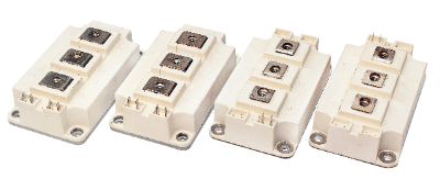
An IGBT module is a highly integrated module that combines multiple IGBTs (Insulated Gate Bipolar Transistors) into a single module.

IGBTs were invented in Japan in the late Showa period (1926-1989) by combining the advantages of the conventionally used base current control type bipolar transistor and the gate voltage control type field-effect transistor (FET), whose weaknesses were improved, with device structures and process innovations.

Initially called insulated gate bipolar transistors, they were later called IGBTs, an acronym for “insulated gate bipolar transistors.”

Uses for IGBT Modules

Although today it is called power electronics technology, IGBTs were then a special world technology for specialists only that had not seen the light of day very often. However, the use of IGBT Modules, which are stored inside inverter air conditioners and other electrical appliances, has expanded dramatically, especially in high-power products, due to the use of inverters (energy saving through power conversion technology) and the use of compact, high-efficiency modules for components.

Today, it is a well-known fact that IGBTs and their modules are commonly used in products that require large amounts of power.

Principle of IGBT Modules

The IGBT is an epoch-making power semiconductor created in Japan that uses a conventional bipolar transistor structure for the parts where large current flows, and switches the base part, which is the control part of the bipolar transistor, to a FET gate circuit structure (previously used only in signal circuits for weak power systems, and capable of high-speed control with low loss). This is a revolutionary power semiconductor created by Japan. The IGBT Module is a compact and highly functional module that contains multiple IGBTs, including diodes for protection circuits and ICs for driving circuits.

IGBTs also exist as discrete components, and it is possible to build a circuit similar to that of a module using discrete components. However, when a circuit is built as a single item, the board size is generally twice or more the size of a module, and there are concerns about the possibility of signal delays, instability, and other malfunctions due to the wiring patterns on the board, which can cause many problems for the user.

In contrast, modularization allows high-density wiring and reliability through improved heat dissipation, making it relatively easy for users to use IGBTs in their own products. This is the biggest advantage of using IGBT Modules instead of IGBTs alone.

As a practical example of an IGBT module, let us illustrate a module containing six IGBTs that drive a mainstream brushless motor. The module is characterized by the fact that the module package is filled with insulating material, and the wiring inside the module is as short and thick as possible to reduce electrical losses.

A heat sink is also added to the module to enable operation of the IGBTs with clearly lower losses and higher heat dissipation than when mounted on a board as a single unit. Thus, the modularization of IGBTs enables both high-efficiency operation and downsizing of equipment, compared to the use of single components (discrete).

Other Information on IGBT Modules

Evolution of the IGBT Module (IPM)

IGBT modules are now also called IPMs (Intelligent Power Modules), which contain high-voltage drivers that used to be external to the

IGBTs, and the technological innovation is still ongoing. In order to improve the performance and functionality of conventional modules that integrate multiple IGBTs in a single package, IGBT modules are often called IPMs, which integrate IGBT-specific driver ICs and various protection circuit ICs for overcurrent and overheat protection together with the IGBTs, as well as compact and heat-dissipating measures.

IPM is a field in which Japan, the creator of IGBTs, is leading the world as a technology in which it excels. The field of power electronics using new semiconductor materials such as SiC and GaN, which are wide band gap semiconductors, has been booming in recent years, and there is a movement to replace IGBTs on Si substrates with SiC-MOSFETs and GaN-FETs, which have superior characteristics, as in the electric vehicle field, such as EVs. There is also a movement to replace IGBTs on Si substrates with SiC-MOSFETs and GaN-FETs, which have superior characteristics.

However, these new semiconductor material substrates are still not as good as Si substrates in terms of wafer size, cost, and manufacturing capacity, so for the time being, devices and modules will continue to be separated for product applications.

カテゴリー
category_usa

Air Leak Tester

What Is an Air Leak Tester?

Air Leak Testers
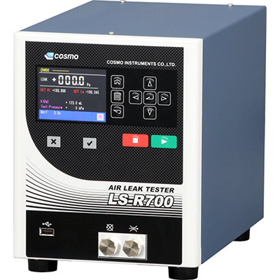
An air leak tester is a device to detect air leaks from inside an object.

Leak testing is performed by pressurizing or depressurizing the inside of an object and detecting the pressure with various methods, such as direct pressure or differential pressure. The appropriate type of air leak tester depends on the shape of the object and whether it contains anything other than air or water.

Unlike a simple leak test using soapy water, an air leak tester can accurately detect the location and amount of leaks.

Uses of Air Leak Tester

Air leak testers can be used not only to simply check for leaks, but also to quantitatively determine the amount of leakage and to automate inspections.

Specific leak inspections include the following:

Air leak testers are also used for leak testing of circuits for flow control, and are often used to inspect automotive parts because many automotive parts, such as washer fluid tanks and airbags, do not allow air leaks.

Principle of Air Leak Tester

Leak testing methods are specified in detail in “JIS Z 2330:2012 Types and Selection of Leak Testing Methods”.

There are many leak testing methods that use air or other gases, including the immersion method, the foaming method, the pressure change method, the differential pressure change method, the flow measurement method, and the ultrasonic method.

1. Immersion Method

The immersion method involves pressurizing an object with gas, submerging it in a tank of liquid, and checking the bubbles that emerge. Since this method is mainly a visual inspection, it requires the skill of the operator and has the disadvantage of causing variation. Also, quantitative data management is difficult.

2. Foaming Method

This method applies a foaming liquid containing a surfactant, etc., to the surface of an object and detects gas leakage by the foaming phenomenon. This method is more sensitive to leakage than the immersion method.

3. Pressure Change Method

The pressure change method is a method of adding or reducing internal pressure to an object and checking the pressure at which the internal pressure becomes constant. 

4. Differential Pressure Change Method

The differential pressure change method is almost the same as the pressure change method, but checks the change in differential pressure between the object and the reference item.

5. Flow Measurement Method

The flow measurement method applies internal pressure to the object and measures the flow rate to compensate for air leakage.

6. Ultrasonic Method

This method uses an ultrasonic detector to detect the ultrasonic waves generated when gas leaks from the leakage point of an object.

Types of Air Leak Testers

Air leak testers are broadly classified into direct pressure type and differential pressure type.

1. Direct Pressure Type Air Leak Tester

The direct pressure type air leak tester performs leak testing by continuously measuring actual pressure. First, the object is pressurized or depressurized. During the pressurization and depressurization processes, the temperature and volume of the air are unstable, leading to fluctuating pressure. Therefore, the tester waits until equilibrium is reached at a certain pressure.

Once equilibrium is confirmed, the pressure is continuously measured. If there is a leak somewhere, this pressure will slowly drop, which can be detected to check for leaks. 

2. Differential Pressure Type Air Leak Tester

The differential pressure type air leak tester is a method of measuring the differential pressure from a reference pressure. In this method, a leak-free measuring object called a master is prepared, and the master is connected to the object.

Then, as in the direct pressure method, the master is pressurized and balanced, and the pressure difference is measured by a sensor connected between the master and the object. If there is no leakage anywhere in the object, no differential pressure is generated, but if there is a leak in the object, a differential pressure is detected based on the amount of leakage.

How to Select an Air Leak Tester

1. Workpiece Characteristics

A pressurized type leak tester is suitable for workpieces that are used under pressure or that contain liquid inside the workpiece. 

2. Workpiece Shape

For example, an internal pressure type leak tester is suitable for a workpiece with many openings, while an external pressure type leak tester is suitable for a workpiece with few openings.

3. Pressure Reduction Method

If the workpiece is to be used under negative pressure, a leak tester with a reduced pressure method should be selected.

Other Information on Air Leak Tester

Advantages of Introducing Air Leak Tester

1. Automation and Labor Saving
Leak testers can quantify pressure changes and other data, enabling automated inspections and labor saving processes. 

2. Quality Improvement
Leak testing can be quantitatively monitored and inspection can be performed without relying on human skill. This improves accuracy and contributes to quality improvement. In addition, data can be statistically processed and analyzed.

3. Cost Reduction
Cost reduction benefits include fewer complaints, lower defect rates, and more efficient inspections.

カテゴリー
category_usa

Ball Splines

What Is a Ball Bearing Spline?

Ball Bearing Splines

A ball bearing spline is one of the linear motion bearings and is a mechanical element used mainly where smooth linear motion is desired.

A ball bearing spline has a spline, which is a groove continuously dug in the longitudinal direction of the shaft that serves as the axis of linear motion. By sandwiching it on top of the shaft by an outer cylindrical part called a spline nut, smooth axial motion and rotational motion can be achieved on a single axis.

A ball bearing spline has several similar machine elements, but among them, it is the most suitable machine element when a smooth linear movement and rotational movement around an axis are also to be conveyed, while taking a relatively large load.

Uses for Ball Bearing Splines

Ball bearing splines are used in a variety of industrial machinery in situations where rotational and vertical motion are required simultaneously. For example, ball bearing splines are used in robot arm movements and in rotary polishing equipment, where the ball bearing must rotate and press against the workpiece at the same time.

ball bearing splines are also used in conveyor systems and other applications that require smooth, long-stroke single-axis motion.

Principle of Ball Bearing Splines

A ball bearing spline transmits rotational torque by means of rolling balls and a spline fit. First, the rolling motion consists of multiple guide grooves on the outside of the shaft, which serves as a guide, and multiple steel balls rolling between elliptical orbits of arbitrary curvature on the inside of an outer cylindrical part called a spline nut.

The steel balls are coated with lubricant and roll between the spline nut and the spline shaft with very little friction. On the other hand, when the shaft rotates, the steel balls are fitted in the spline groove, so the shaft and spline nut do not shift in the direction of rotation. These two mechanisms allow linear motion along the spline shaft and rotational motion on a single shaft.

How to Select a Ball Bearing Splines

The internal structure of all ball bearing splines is almost the same. However, the load and torque that can be handled vary depending on the spline shaft size and other factors. Therefore, it is important to select the appropriate spline shaft size according to the design of the equipment to be used.

It is also essential to consider options that suit the operating environment, such as using a stainless steel material if the equipment is expected to be used in a space with corrosive gases or humidity, or changing the ball lubricant to a special lubricant for situations where high cleanliness is required.

Other Information on Ball Bearing Splines

1. Rotary Ball Spline

A rotary ball spline is a mechanical element with a mechanism that allows linear and rotary motion in a single assembly. It is characterized by the addition of a mechanism called a cross roller for smooth rotational motion, which is independent of the standard ball bearing spline.

The integral nature of the spline and rotating part allows for a significant reduction in the number of parts compared to conventional mechanisms, and reduces the accumulated errors in installation. In addition, the cross roller is placed directly on the outer sleeve of the ball bearing spline, making it lightweight and compact. It is lighter and easier to install than conventional mechanisms.

Rotary ball splines are used in assembly machines, loaders, and laser milling machines, including horizontally articulated industrial robots called SCARA robots.

2. Difference Between Ball Bearing Splines and Linear Bushings

Linear bushings are rolling-guided linear motion mechanisms and are used in combination with linear shafts to provide infinite linear motion using the rolling of steel balls. The most obvious difference from the outside is that a ball bearing spline has a spline groove on the shaft, while a linear bush has no groove on the shaft.

In a linear bushing, the balls are arranged in a straight line with respect to the bushing, and the balls slide in point contact with the shaft. In contrast, in a ball bearing spline, the balls roll over the grooves on the spline shaft, so the contact area between the balls and the shaft is large and they do not shift in the direction of rotation, so torque can be transmitted at the same time.

カテゴリー
category_usa

Chip Resistors

What Is a Chip Resistor?

Chip Resistors
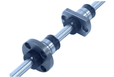
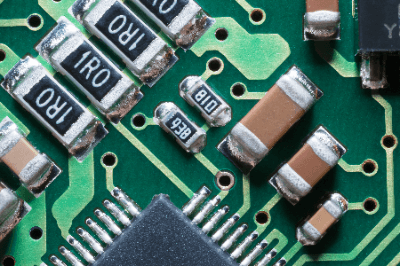
Chip resistors, also called surface mount resistors, are rectangular resistors with a metal film as a resistive element on a small
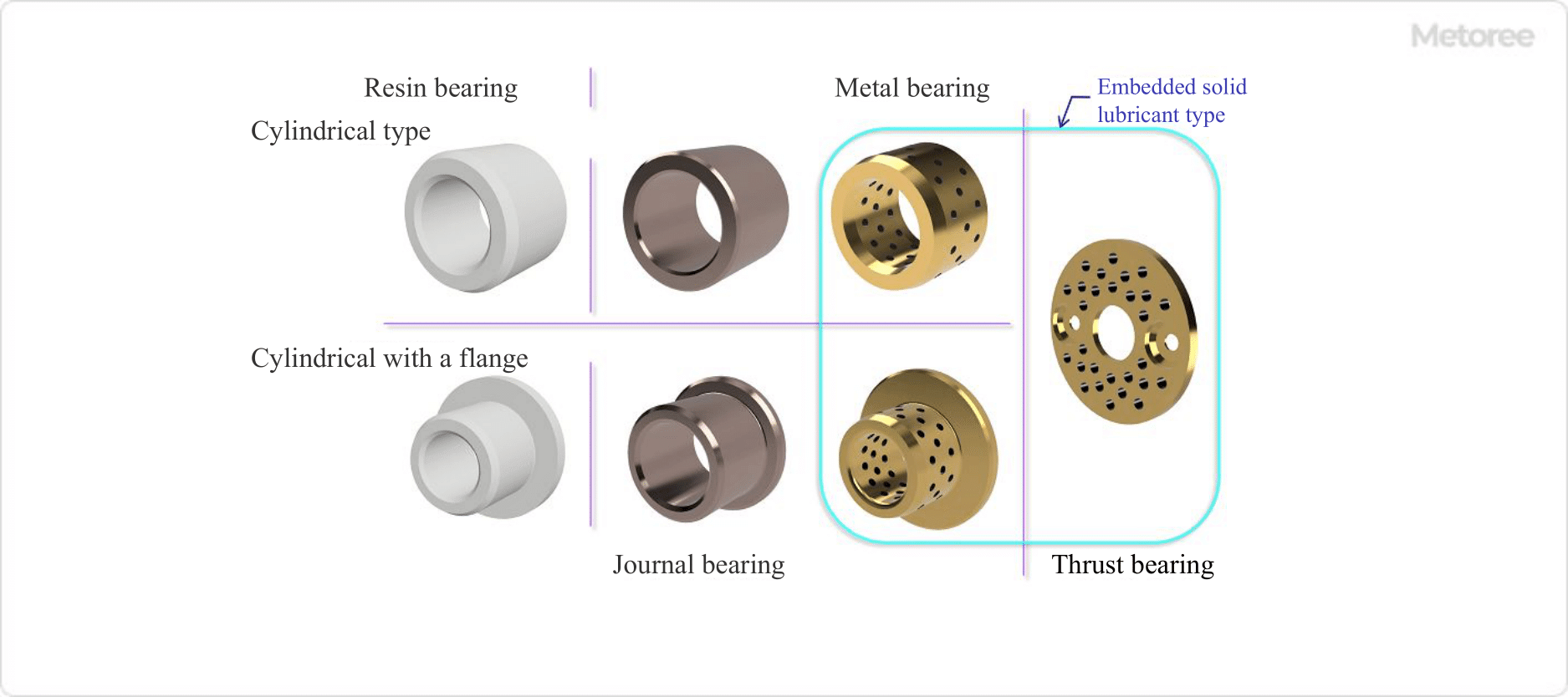
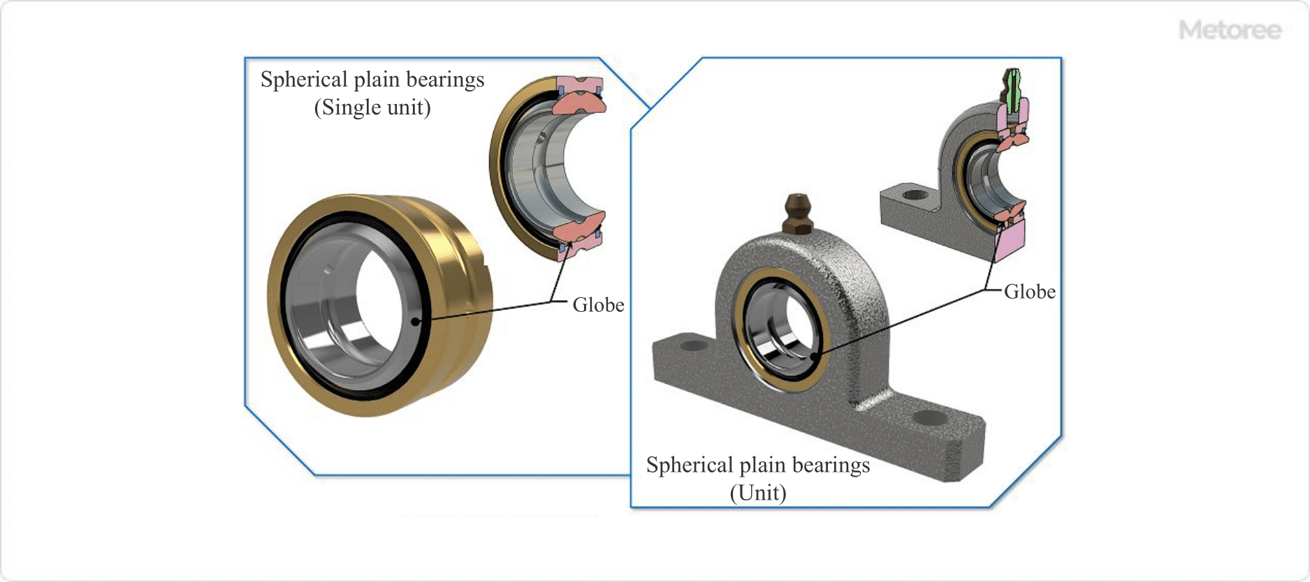
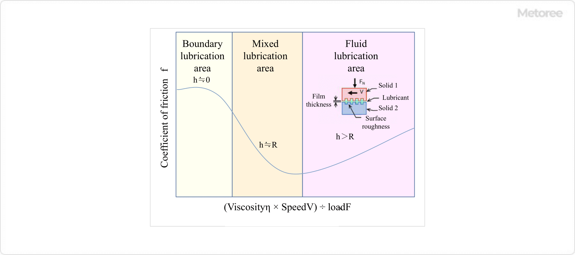
 ceramic substrate.

In general, chip components refer to all small surface-mount passive components. Chip components are made of capacitors, resistors, fuses, coils, transformers, etc., all of which are characterized by having fixed electrodes.

In older resistors, flexible lead wires were used as electrodes to be inserted into holes in printed circuit boards, but chip resistors have fixed electrodes that are soldered directly to the surface of the printed circuit board.

Uses of Chip Resistors

Resistors, along with capacitors and coils, are the most basic passive elements in electronic circuits. Chip resistors are used in all kinds of electronic devices, playing various roles, such as limiting current, detecting voltage, and setting bias voltage.

In recent years, demand for chip resistors has been growing rapidly, especially in the field of mobile communications, particularly for cellular phones and smartphones. Chip resistors are sold in a variety of products to suit different purposes and applications, so it is necessary to determine the performance and characteristics of the resistor according to the required performance.

Principle of Chip Resistor

Chip resistors are classified into the following three types depending on the resistive element to be formed on the ceramic substrate.

1. Thick-Film Chip Resistor

Thick-film chip resistors employ metal glaze as a resistive element and form a film several μm thick. They are called thick-film chip resistors because they are thicker than the thin-film chip resistors described below.

Resistance can be adjusted by trimming a part of the resistive element after the metal-glaze film is formed. Since the metal-glaze film can be formed on a ceramic substrate at once using the screen printing method, these resistors are relatively inexpensive and versatile. Various constants and sizes are available.

2. Thin-Film Chip Resistor

The structure is almost the same as that of thick-film chip resistors, but the resistive element is a metal alloy, and the resistive element is formed on a ceramic substrate using the vacuum evaporation method. The thickness of this resistive element is extremely thin, about several nm. That is why they are called thin-film chip resistors.

Thin-film chip resistors have a small error (±1% or less) with respect to the nominal resistance value and a small temperature coefficient, so they are employed when accurate resistance values are required. Another feature of thin-film chip resistors is that they show little change in resistance value over time. 

3. Metal Plate Chip Resistors

Metal plate chip resistors use a metal plate as a resistive element, enabling the production of resistors with small resistance values. Resistors of 1 mΩ or less are also available for current detection. Also, because of its excellent heat dissipation and large thermal capacity, it can carry a relatively large current.

On the other hand, its disadvantage is that it is difficult to produce high resistance values and is expensive. The ceramic substrate on which the resistor is based is mainly made of alumina, an oxide-based ceramic, and has excellent strength, thermal conductivity, and insulation properties.

Types of Chip Resistors

The following high-performance products are available for chip resistor according to the market needs. 

1. Sulfur-Resistant Chip Resistor

Silver is used for the internal electrode of general chip resistors, and if left in an atmosphere containing sulfur, the silver reacts with sulfur to form silver sulfide, which is an insulator, and this growth is likely to cause poor conductivity of the internal electrode.

Therefore, resistors with sulfurization countermeasures should be used in environments where sulfur components are present in the atmosphere, such as near active volcanoes or in the vicinity of materials containing sulfur.

Specifically, a resistor has been developed in which the internal electrode is changed to a material that does not react with sulfur, instead of silver.

2. Surge/Pulse Resistant Chip Resistors

When surge voltages or pulses are frequently applied to resistors, such as in switching circuits or circuits prone to electrostatic discharge, it is necessary to use resistors that are not easily damaged even when large amounts of instantaneous power are applied. For this reason, anti-surge and anti-pulse chip resistors are also available. 

3. Chip Resistors With High Measurement Accuracy

Precision equipment, such as measuring and control instruments, requires high-precision resistors with small resistance error (resistance tolerance) and resistance change with temperature (temperature coefficient of resistance). 

4. Chip Resistors for Current Detection

Chip resistors for current sensing applications have a small resistance value. Metal plate chip resistors are mainly used for current sensing to detect overcurrent and remaining battery charge.

There is also a growing need for lower resistance to reduce power consumption in circuits and for high-precision resistors that ensure excellent resistance temperature coefficient even in harsh temperature environments.

5. Chip Resistors With Long Electrodes

Chip resistors originally had electrodes laid out on the short side. Since the resistive element itself has low heat dissipation, heat dissipation through the electrodes greatly affects the rated power of Chip Resistor.

Therefore, several resistors makers have introduced products with electrodes on the long side of the chip resistor to increase the electrode area and improve heat dissipation. These chip resistors are called “long side electrode type” or “long side chip resistor.”

Conventional chip resistors are sometimes called “short side electrode type” to distinguish them.

Other Information on Chip Resistors

Size of Chip Resistors

Typical sizes of chip resistors are as follows:

  • 6.mm x 3.mm
  • 5.0mm x 2.5mm
  • 4.5mm x 3.2mm
  • 3.2mm x 2.5mm
  • 3.2mm x 1.6mm
  • 2.0mm×1.25mm
  • 1.6 mm x 0.8 mm
  • 1.0 mm x 0.5 mm
  • 0.6 mm x 0.3 mm
  • 0.4 mm x 0.2 mm
  • 0.3 mm x 0.15 mm

However, the rated voltage and power rating are restricted by size, and the larger the size, the more advantageous, so the size cannot be freely determined. On the other hand, small resistors can be selected for circuits that operate at relatively low voltages, but the mounting equipment (mounter, etc.) that can handle them may be restricted.

The size with the largest shipment volume for chip resistors is “1005 (1.0mm x 0.5mm),” while the previous mainstay “1608 (1.6mm x 0.8mm)” size is decreasing in volume. On the other hand, “0603: 0.6mm x 0.3mm” size, which will be the mainstream in the future, is increasing in volume.

In addition, “03015: 0.3mm x 0.15mm” size was commercialized as a small chip resistor in October 2011, and “0201: 0.2mm x 0.125mm” size is under development by resistor manufacturers.

カテゴリー
category_usa

Plain Bearing

What Is a Plain Bearing?

Plain BearingsPlain bearings are bearings that directly support the rotation of a shaft or the linear motion of moving parts by the sliding surfaces of the bearing. Since the rotating shaft or moving parts are in direct contact with the sliding surfaces of plain bearings, frictional forces are high and frictional heat is generated. For this reason, the contact surfaces are lubricated with oil by impregnating metal with a lubricant on the plain bearing sliding surfaces, or with a resin material with high lubricating properties.

Plain bearings that do not use lubricant are called dry bearings. Plain bearings are inexpensive, easy to use, and flexible in terms of material and size, and they are used for different purposes and in different operating environments.

Plain bearings are classified into the following three types:

  • Plain Bearing
  • Sliding Bearing
  • Slide Bearing

Uses of Plain Bearings

Plain bearings have the following characteristics (especially when compared to rolling bearings):

    • Simple structure and shape
    • Compact in size
    • High-speed performance (high-speed rotation)
    • Not suitable for low speed performance (Low-speed rotation)
    • Relatively large allowable load
    • Quiet noise and low vibration
  • Long life

Types of Plain Bearings

Plain bearings used in general industrial applications are classified according to “load type,” “material,” and “shape/structure.”

ISO 4378-1 classifies them as follows:

Figure. 1 Classification of plain bearings (types)(From ISO 4378-1)

Figure. 1 Classification of plain bearings (types)(From ISO 4378-1)

1. Load Type

Load types are divided into four types, namely: hydrodynamic bearings, hydrostatic bearings, journal bearings, and thrust bearings.

Dynamic and Hydrostatic Bearings
In hydrodynamic bearing, the dynamic pressure generated by the rotation of the shaft forms an oil film between the shaft and the plain bearing surface to support the shaft. There are several ways to generate hydrodynamic pressure, such as wedging the gap or applying sliding surface construction to the sliding surfaces. In general, plain bearing passive is often used to indicate a hydrodynamic bearing.

Hydrostatic bearings support a shaft by supplying oil (lubricating oil) or compressed air to the bearing from equipment or facilities outside the bearing and filling the pocket between the shaft and bearing.

Figure 2. Hydrodynamic and hydrostatic bearings

Figure 2. Hydrodynamic and hydrostatic bearings

Journal Bearings and Thrust Bearings
Journal bearings are used when loads are applied in the centerline direction (radial direction) of the shaft. Thrust bearings are used when the load is applied to the bearing in the direction perpendicular to the shaft centerline (thrust direction).

Figure 3. Journal and thrust bearings

Figure 3. Journal and thrust bearings

2. Material

There are two types of materials: resinous and metallic.

Resin Type
The following are examples of resin-based materials:

Plain The following are examples of metallic materials:Bearings are lubricated with oil or graphite to improve lubricity and are used without lubrication in most cases. They may also be used in combination with metals to improve mechanical strength.

Metallic Materials
Examples of metallic materials are listed below.

White metals, copper alloys, and aluminum alloys are the most common metallic materials used with lubricants. White metals are often used for static loads and ship engines, while copper-based alloys are often used for bushings due to their superior wear resistance.

Aluminum alloys, on the other hand, are used in a wide range of applications, including engine applications and bushings. Oilless Plain Bearings are lubricated by adding lubricant, coating the surface, or embedding a solid lubricant material. Oilless Plain Bearings are called Oilless Bearings.

Shape and Structure
Types by shape and structure are divided into cylindrical, cylindrical with flange, disk (thrust bearing), and spherical (spherical thrust bearing).

Figure 4. Types of sliding bearings (1)

Figure 4. Types of sliding bearings (1)

Figure 5. Types of sliding bearings (2)

Figure 5. Types of sliding bearings (2)

Principle of Plain Bearings

Plain bearings are supported by the sliding surfaces of the rotating shaft or moving parts and the sliding surfaces of the Plain Bearing making contact with each other. Therefore, it is important to deal with the friction that occurs between the surfaces (sliding surfaces).

In general, plain bearings, lubricating oil, lubricant, or air is used on the sliding surfaces to reduce frictional resistance. As such, the state of lubrication of the sliding surfaces is very important.

The lubrication condition is classified into the following three types: 

1. Boundary Lubrication

The sliding surfaces are almost solidly lubricated due to high friction without sufficient lubrication film formation, which may lead to seizure and sticking.

2. Mixed Lubrication

Sliding surfaces have almost the same surface roughness and lubricating film thickness, and are mixtures of fluid and solid contact, which is not completely satisfactory.

3. Fluid Lubrication

Sliding surfaces are well lubricated with sufficient lubricating film and are not in direct contact with each other, with no mutual wear.

Figure 6. Trispec curve

Figure 6. Trispec curve

Plain bearings can be lubricated by “forced lubrication,” “oil bath,” “splash lubrication,” or “drop lubrication,” depending on the operating conditions of the bearing. Forced lubrication is a method in which lubricating oil is pumped to the bearing lubrication area to ensure that a constant amount of lubricating oil is supplied. Oil bath and splash lubrication do not require lubrication equipment, and can be made into a simple structure. Drip lubrication is not suitable for high-load operation because the amount of lubricating oil is small.

For forced lubrication, there are two methods: lubricating the housing side and lubricating the shaft side. It is also possible to improve the cooling effect by installing oil grooves on the housing and shaft. However, the lubricating film may become discontinuous, resulting in a reduction in bearing load capacity. Hence, care must be taken in the design of the oil groove.

In environments where lubricating oil cannot be used (e.g., at high temperatures), solid lubricants may be used. Solid lubricants include graphite and PTFE. Plain Bearings can have a long service life if the hydraulic pressure, oil film, etc. are accurately controlled.

Other Information on Plain Bearings

Plain Bearing Standards

Below are the ISO standards for plain bearings:

The specifications of rolling bearings are specified by standards, so that all manufacturers have the same specifications for fitting tolerances, manufacturing tolerances, clearance tolerances, and so on, depending on the bearing type. Therefore, they are interchangeable and can be used as general-purpose parts.

Plain bearings, on the other hand, do not have a common international standard. Therefore, they are not interchangeable and cannot be used as general-purpose parts. Therefore, it is necessary to make a decision based on the application, operating environment, and design specifications.

カテゴリー
category_usa

Fieldbus Components

What Are Fieldbus Components?

Fieldbus Components
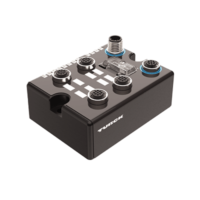
Fieldbus Components are a bus system that connects field devices, such as sensors and actuators with controllers such as PLCs and DCSs in factories and plants through digital communication.

By using Fieldbus Components, wiring can be omitted, the amount of data can be increased, and the system is more resistant to noise than conventional analog or parallel signals. It also makes it possible to perform self-diagnosis and change settings of field devices remotely.

There are various types of fieldbuses, with PROFIBUS, CANopen, and AS-i being typical examples.

Uses of Fieldbus Components

Due to their versatility and efficiency, Fieldbus Components are used in a wide variety of industries, especially in manufacturing. It is an important tool for cost reduction, efficiency, and optimization.

1. Manufacturing Industry

Process control and monitoring are key elements in manufacturing. Fieldbus Components enable process automation and efficiency by linking devices such as sensors and actuators in a unified communication platform.

2. Process Control

In process control in chemical plants and refineries, Fieldbus Components monitor process variables such as temperature, pressure, and flow in real time and make the necessary adjustments to maintain optimal conditions.

3. Automation

In building and infrastructure automation, Fieldbus Components integrate a wide variety of devices such as lighting, heating and cooling, and safety systems into a single network. This allows operators to monitor and control all systems from a central location.

4. Automotive Manufacturing

In automotive manufacturing, Fieldbus Components link stations on the production line, aggregating data from actuators and sensors and enabling precise coordination between stations.

Fieldbus Components Principle

In a nutshell, the principle of Fieldbus Components is information sharing between devices using digital communication. Fieldbus Components are used in a variety of fields, including manufacturing and process control due to the following characteristics:

1. Multi-Drop

Fieldbus Components are a communication network that connects various devices in a factory or plant with a single cable. This allows each device to send and receive data over a single fieldbus cable without the need for separate connecting cables. This is also called digital multi-drop technology and allows multiple devices to share the same communication line.

2. Communication Protocol

Fieldbus Components use a communication protocol. A communication protocol is a set of rules that govern how data is sent and received. Fieldbus Components follow these rules to exchange information between devices. This allows any device to be compatible with any other device and ensures accurate transmission of information. 

3. Real-Time Performance

Another important principle of Fieldbus Components is real-time capability. In factory and plant operations, information must be transmitted quickly and accurately. Fieldbus Components accomplish this by transmitting and receiving data in real time.

For example, data from sensors can be immediately sent to the control system, enabling the system to react quickly, for example, to move actuators as needed.

Additional Information on Fieldbus Components

Differences Between Fieldbus Components and Industrial Ethernet

Factory networks are classified into information networks, controller-to-controller networks, and field networks. Industrial Ethernet is used for controller-to-controller networks, while Fieldbus Components are used for field networks.

In 2017, the number of industrial Ethernet installations reversed the number of Fieldbus Components installations. The factory-wide IT initiative, Industry 4.0, which was proposed in Germany, is beginning to be realized.

カテゴリー
category_usa

Shielded Cables

What Is a Shielded Cable?

Shielded Cables
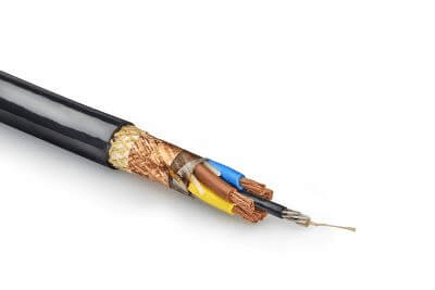
A shielded cable is a cable in which the metal conductor portion that transmits signals and power is covered with a grounded metal layer.

The grounding metal layer is made of a thin film or other material that is braided into a structure. Covering the conductor section with a metallic layer blocks electromagnetic waves from the outside and, at the same time, prevents leakage of electromagnetic waves to the outside.

This structure contributes to high-speed communication in the communication and instrumentation fields and is important for ensuring safety in the high-power field. Multi-core cables also play a role in canceling out inter-wire noise.

Uses of Shielded Cables

Shielded cables are widely used in LAN cables for OA equipment and loudspeakers for audio equipment.

The purpose of these applications is to protect equipment from electromagnetic waves emitted from outside. In contrast, shielded cables are also used in high-voltage power distribution applications. The purpose of these applications is to prevent the generation of electromagnetic waves.

Principle of Shielded Cables

The main components of a shielded cable are the conductor, the shielding layer (shield), the insulation layer, and the sheath.

In ordinary metal cables, the outer conductor is covered by an insulating layer. Shielded cable, on the other hand, is covered with a shielding layer, such as a thin metal film, on top of the insulation layer covering the conductor.

The outside of the shielding layer is covered with an insulating film called a sheath to protect the wire from the outside environment. By grounding the shielding layer, signal cables can be protected from noise. Shielded cable can also be used for power cables to cancel out the electromagnetic waves generated.

Canceling electromagnetic waves from power cables is often used from a safety perspective because it leads to the prevention of electric shock accidents due to induction.

Types of Shielded Cable

Shielded cables include “electrostatic shielded cables,” which prevent external noise, and “electromagnetic shielded cables,” which prevent magnetic flux caused by electric current from affecting external equipment. Since the method of grounding the shielding layer differs depending on the type, it is important to ground the cable using a method appropriate for the type.

1. Electrostatic Shielded Cable

Electrostatic shielded cable is a cable with a core wire covered with metallic tape, such as copper or aluminum, or mesh braided wire.

This absorbs external noise and conducts it to ground, preventing noise from entering the core wire. It is mainly used for signal and communication cables. The basic grounding method for electrostatically seeded cables is single end grounding. This is to prevent the return current from flowing into the shield.

If both ends are connected to ground, there is a greater possibility of current flowing through the shield, and there is a risk of noise being generated from the shield due to current flow. Also, if the shield is not connected to ground, not only will the shield not be effective, but the electrical charge accumulated in the shield will be released in some way, causing noise in the signal, so care must be taken. When shielded cable is used, it must be grounded. 

2. Electromagnetic Shielded Cable

Electromagnetic shielded cable is a cable with a core wire covered with iron and copper to prevent magnetic flux caused by electric current from escaping.

The disadvantage of this cable is that it is vulnerable to bending and folding due to the iron covering. It is mainly used for power cables, motors, and other cables in which large currents flow. When grounding an electromagnetically shielded cable, choose between grounding at both ends or at one end, depending on the distance. For long-distance power transmission, grounding should be done at both ends, and for short distances, grounding should be done at one end. In both cases, the grounding wiring should have as low electrical resistance as possible to increase the shielding effect.

Generally, copper plates or copper piles are embedded several meters underground to reduce grounding resistance. This underground buried conductor is the grounding pole. Wires rising to the ground surface from the grounding pole are connected to a copper bar called a ground bar or bus bar.

Stepping Motors

What Is a Stepping Motor?

Stepping Motors

A stepping motor refers to a motor whose rotation angle can be controlled by pulse signals and is a type of motor that can guarantee high positioning accuracy.

Also known as a pulse motor, the rotation angle is determined by the number of pulse signals, which are control signals, and the number of phases of the motor, while the rotation speed depends on the pulse frequency, which corresponds to the speed of the pulses. It features high positioning accuracy and torque with open-loop control, coupled with its relatively inexpensive and simple motor configuration.

Uses of Stepping Motors

Stepping motors are used mainly in applications where positioning accuracy is required, as they are structurally suited for precise and reversible angle control. An example is a drive motor used to express two-dimensional movements of robot devices, such as automatic transfer equipment.

By combining a high-precision ball screw with a stepping motor, the feed rate of a stage can be expressed with extremely high precision and repeatability. Stepping motors can also be used to adjust the opening angle of valves precisely on coating machines that spray a certain amount of paint depending on how the valves are opened, allowing for more elaborate operations.

Principle of Stepping Motors

The inside of a stepping motor consists of a rotor connected to a shaft and several stators installed around the periphery of the rotor. The rotor section is further divided into two parts, each of which is magnetized so that its N and S poles are in opposite phase.

The stator is characterized by the presence of small teeth, which is precisely controlled. 2-phase stepping motors, for example, are magnetized with the same polarity for the stator facing each other and in the opposite direction for the stator next to it. Therefore, the stator attracts and repels the unevenness of the rotor, and the rotor is held in an energetically stable position relative to the stator’s magnetization state.

Then, when current is applied to reverse the polarity of the stator, the rotor rotates by one stator. In a 5-phase stepping motor, this is controlled sequentially in 5 steps, thus enabling finer angle control.

Other Information on Stepping Motors

1. Torque of Stepping Motors

The output torque of a stepping motor varies depending on the rotational speed. In general, the torque is high when the rotational speed is slow and low when the rotational speed is high. When selecting a stepping motor, check the motor’s rotational speed-torque characteristics chart and select a motor so that the required torque at the rotational speed to be used falls within the pull-out torque curve.

In particular, the pullout torque at high rotational speed is about 20% of the maximum excitation quiescent torque.

Torque characteristics also vary depending on the driver used, internal structure, and input voltage, even for motors of the same external dimensions. Therefore, motor selection should be made in consideration of the manufacturer, driver combination, and input voltage.

2. Drivers for Stepping Motors

A control device called a driver is required to operate a stepping motor. The driver controls the current voltage that is applied to the stepping motor to control the rotation speed, amount of rotation, and other factors.

Drivers are available in constant-current and low-voltage drive systems, but the constant-current system is often used because of its superior torque characteristics at high speeds. Generally, a pulse train is input to the driver from a host control device as an indication of rotation speed and amount, and the motor is rotated at the indicated speed and amount according to the input pulse train.

Some drivers are equipped with a function called micro-step. Stepping motors rotate with the basic step angle as the minimum rotation angle, but drivers with the micro-step function can adjust the current flowing to each coil to subdivide the basic step angle and increase the resolution of rotation electrically.

It also has the effect of reducing vibration and noise, overshoot at each step angle, and shock mitigation at startup and shutdown. The resolution of the micro-step function can be selected by DIP switches, etc., depending on the intended use. 

3. Use With AC Servo Motors

AC servo motors are often quoted in connection with stepping motors.

Suitability of Stepping Motor
AC servo motors have a built-in encoder and feedback control, so the rotational torque is almost constant regardless of the rotation speed. Stepping motors, on the other hand, are not suitable for this application because their rotational torque decreases at high rotational speeds. Conversely, if low-speed rotation is the main use, stepping motor is suitable for this application.

Stepping motors are mainly available on the market in open-loop control type, but there are also products that can be close-controlled by attaching an encoder for improved efficiency. In such cases, however, it will be necessary to review the other advantage of these motors, which is their relatively small size, simple configuration, and low cost.

Applications for Which AC Servo Motors Are More Suitable
Applications that require AC servo motors are those that require advanced rotation control using multiple motors. Since open-loop control cannot be expected to compensate for motor-to-motor motion by sensing, AC servo motors are better suited for this application than stepping motors, as is the case with high-speed rotary motion.

Resettable Fuses

What Is a Resettable Fuse?

Resettable Fuses
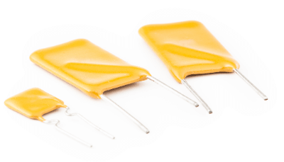
A resettable fuse is an electronic component that can be used repeatedly while serving as a fuse to prevent overcurrents.

Also called a polyswitch or polyfuse. A PTC thermistor is made of conductive polymer and differs from a fuse in basic principle. A fuse interrupts a circuit by breaking the element due to heating when an overcurrent flows through it.

Resettable fuses, on the other hand, limit the current by increasing the temperature inside the element due to overcurrent, causing the resistance value to increase. Since many products are smaller than fuses, they can be used in smaller spaces, and their structures are resistant to breakage, shock, and vibration.

Uses of Resettable Fuses

Resettable fuses are used to protect circuits that are subject to repetitive overcurrents. They are also used for intentional short-circuits in high-density mounting.

The following are examples of applications for resettable fuses:

  • Small motors and switching power supplies
  • Satellite receivers
  • Fire alarms
  • Electric carpets
  • Communication devices such as smartphones and tablets
  • Computers

However, resettable fuses are not suitable for high current circuits because they use electronic components. Fuses with fusing elements are used for current-limiting fuses for high-voltage circuit protection.

Principle of Resettable Fuses

Resettable fuses consist of a conductive polymer sandwiched between metal electrode foils. Leads are soldered or welded to connect to the electrode foil, similar to the principle of PTC thermistors, which has a property of increasing resistance with increasing current.

Conductive polymers consist of conductive particles such as carbon and nickel dispersed in an insulating polymer. Resistance can be adjusted by changing the amount and material. Resistance variations can reach 10,000 to 1,000,000 times.

When the internal temperature of a resettable fuse increases due to overcurrent, the resistance value will increase, limiting the current. Unlike fuses, resettable fuses do not blow, and current flow returns to normal when the internal temperature drops. Therefore, they can be used repeatedly.

When the temperature changes at a higher current value, the resistance value increases rapidly. This phenomenon occurs due to the melting of the conductive polymer. However, the reactivity may be low at minute increases in current.

How to Select a Resettable Fuses

Resettable fuses are selected based on the rated voltage, rated current, and mounting method.

1. Rated Voltage

Rated voltage is the height of the voltage at which a resettable fuse will withstand service. If used above the rated voltage, there is a risk of circuit damage or burnout.

Generally, products with a rating of about 72 VDC are widely available. Products with a higher rated voltage, 240 VAC, are also commercially available. Therefore, if a product with a withstand voltage of 400 V system or higher is required, it should be special-ordered. 

2. Rated Current

The rated current is the height of the current that a resettable fuse can withstand for use. When the rated current is exceeded, the resistance value increases, limiting the current value.

Generally, many products are sold in the range of a few amperes. Commercial products are limited to a maximum of about 20A.

3. Mounting Method

The mounting method is to install a resettable fuse. Surface mounting and plug-in terminal mounting products are available.

Surface mounting
Surface mounting is a mounting method in which the fuse is secured to the board with solder, etc., and has the advantage of taking up less space than plug-in terminal mounting. However, many surface mount electronic devices are small, and hand soldering requires proper knowledge and skills.

Some manufacturers do not guarantee the performance of hand soldering in many cases.

Plug-in Terminal Mounting
Plug-in terminal mounting is a mounting method in which leads are plugged into the printed circuit board. The printed circuit board has lead wire mounting holes for easy component mounting, and the lead wires are inserted into these holes for mounting. In addition, it is common to solder the lead wires to the mounting holes to secure the component in place.

Plug-in terminal mounting enables easy mounting of components, but it requires a lot of space. However, if you plan to mount components manually, it is safer to select the plug-in terminal mounting.