カテゴリー
category_usa

DC Power Supply

What Is a DC Power Supply?

DC Power Supplies

A DC power supply is a power supply device that provides DC power.

There are two types of power supplies: DC and AC. A DC power supply is a power supply in which the direction of current and voltage is always in one direction. An AC power supply is a power supply that periodically switches the direction of current and voltage.

Commercial power supplies supplied by electric power companies are generally AC power supplies, which can easily change voltages and shut down. In contrast, semiconductors require DC power for operation, so the power supplied to electronic products must be DC.

Therefore, DC power supply is primarily used for the operation of electronic products.

Uses of DC Power Supplies

DC power supplies are used in a wide range of applications, from everyday products to huge equipment in the industrial field. The following are examples of use

  • AC adapters for charging PCs and smartphones
  • Power supply equipment for streetcars
  • Power supply equipment for LED lighting
  • Inside control boards of air conditioners and refrigerators
  • Power supply equipment for electrolysis and plating factories
  • Power supplies for electric furnaces using direct current

Many home appliances also have DC power supplies inside, but some home appliances, such as fans and incandescent light bulbs, do not have DC power supply units because they use AC power directly.

Principle of DC Power Supplies

A DC power supply (AC-DC power supply) rectifies and regulates AC power to DC power.

There are three main types of DC power supply systems: shunt regulation system, series regulation system, and switching regulation system.

1. Shunt Regulation Method

In the shunt regulation method, a diode and a resistor are connected in series between input and output.
Since AC power can only pass through the diode in a certain direction, DC power is output at the output end.
Although the structure is simple, the heat loss due to the resistance is large, resulting in the lowest efficiency among the three methods. 2.

2. Series Regulation Method

In the series regulation method, elements such as transistors are connected in series between input and output.
Since AC power can only pass through the transistor in a certain direction, DC power is output at the output end.

3. Switching Regulation Method

In the switching regulation method, a switching element switches the AC power supply in the direction of current and voltage. As a result, a constant direction and averaged DC power supplies are output.

Other Information on DC Power Supplies

1. Difference between DC and AC Power Sources

As mentioned earlier, there are two types of power supplies: DC and AC. The features of DC and AC power supplies are listed below.

Features of DC power sources

  • It can be extracted from dry batteries, lead-acid batteries, and other chemical reactions
  • DC power supplies are necessary for the operation of semiconductors
  • No loss due to reactance when transmitting power over long distances
  • No induced electromagnetic waves
  • Expensive equipment for transformer and shutdown

Features of AC Power

  • Power can be drawn from rotating equipment such as synchronous generators
  • It can be easily transformed by a transformer
  • It can be easily shut down when the current becomes zero
  • Countermeasures against electromagnetic waves due to induction are necessary
  • Power factor and transient stability must be considered

Because of the above features, commercial power supplies used by power companies are AC power supplies because they are suitable for large power supplies.
However, in recent years, DC power transmission, which does not require consideration of transient stability and has low loss, is also being considered for high-power transmission.

2. How to Use DC Power Supplies

DC power supplies come in various types and sizes, but all operate in either constant voltage or constant current mode.

  • Constant voltage mode
    Constant voltage mode is a mode designed to operate at a constant voltage. It is used for product verification of electronic circuits that operate at a constant voltage. As a constant voltage mode product, power supplies are widely used in industry.
  • Constant Current Mode
    Constant current mode is a mode designed to operate at a constant current. It is used for transmitting analog signals and dimming LED lights.

DC power supplies built into products often operate in either mode only. Many DC power supply devices for testing and other applications can be manually switched between each mode, so the mode can be changed according to the application.
カテゴリー
category_usa

Humidity and Temperature Sensor

What Is a Humidity and Temperature Sensor?

Humidity and Temperature SensorsA humidity and temperature sensor is a device used to measure temperature and humidity.

Since a single unit can measure both temperature and humidity, it requires little installation time and space.

Uses of Humidity and Temperature Sensors

Humidity and temperature sensors are used to measure temperature and humidity, and are used, for example, in the following fields:

  • Measurement of outside temperature and humidity
  • Sensors for air conditioning equipment, such as air conditioners and heaters
  • Sensors to manage automobile engines
  • Sensors in smartphones, computers, etc.
    Industrial inspections

Principle of Humidity and Temperature Sensors

Humidity and temperature sensors are composed of a temperature sensor and a humidity sensor. Temperature sensors are broadly classified into three types: resistance temperature detectors (RTDs), linear resistors, and thermistors, while humidity sensors are broadly classified into two types: resistance change type and capacitance change type. They are explained in the following order.

1. Temperature Sensors

Resistance Thermometer (RTD)
Resistance thermometer (RTD) is a type of temperature sensor that measures electrical resistance to determine temperature. RTDs utilize the property of electrical resistance of metals such as platinum, nickel, and copper, metal oxides, and semiconductors to increase with rising temperature, and measure temperature by measuring the electrical resistance value.

Linear Resistors
Linear resistors are temperature measuring resistors made of nickel-nickel or palladium alloys and utilize the property that resistance increases almost linearly with temperature. They are not as accurate as resistance thermometers made of platinum or other metals.

Thermistors
Thermistors are elements whose resistance changes with temperature. Temperature sensors use thermistors to measure the temperature by utilizing the correlation between the temperature and resistance of the element. There are two types of thermistors: PTC thermistors (positive characteristic), whose resistance increases with increasing temperature, and NTC thermistors (negative characteristic), whose resistance decreases with increasing temperature.

PCT thermistors are characterized by a sharp rise in resistance at a certain temperature and are suitable for overcurrent protection in the event of a semiconductor thermal runaway. NCT thermistors, on the other hand, have a high resistance at room temperature and a large change in resistance as the temperature rises. Therefore, they are generally used for circuit protection at temperature. The term “thermistor” usually refers to NCT thermistors.

2. Humidity Sensor

Resistance Change Type
Resistance change type temperature sensors are sensors that derive humidity from changes in resistance. They are characterized by a structure in which the comb teeth of the comb-shaped circuit built into the sensor are bridged by a moisture-sensitive membrane made of polymer.

When humidity rises and the humidity-sensitive film absorbs moisture, the resistance of the humidity-sensitive film decreases due to the increase of mobile ions in the film, and conversely, when humidity falls, the resistance increases. In other words, in resistance change type temperature sensors, humidity is derived from the change in resistance value.

Capacitance Type
Capacitance-type temperature sensors convert changes in capacitance into humidity, and are characterized by a humidity-sensitive membrane made of polymer sandwiched between two electrodes. As the humidity increases, the capacitance between the electrodes will increase due to the increase of mobile ions in the moisture-sensitive membrane.

On the other hand, when humidity decreases, the capacitance between the electrodes decreases because the number of movable ions in the humidity-sensitive membrane decreases. In other words, a capacitance-type temperature sensor converts changes in capacitance into humidity.

Types of Humidity and Temperature Sensors

Humidity and temperature sensors are classified by shape, and include IC type humidity sensors embedded in IC chips and wireless type humidity sensors used in the Internet of Things (IoT).

1. IC Type Humidity and Temperature Sensor

IC-type humidity and temperature sensors consist of a sensor element and a measurement circuit, such as A/D converter integrated into a single chip. When using individual sensor elements, it is necessary to design the peripheral circuits according to the application, which is time-consuming and costly.

However, the integrated IC type humidity and temperature sensor does not require such time and effort and can be used easily. In addition, the mounting area required for mounting on a board can be reduced, enabling miniaturization, low power consumption, and low cost.

2. Wireless Humidity and Temperature Sensor

In recent years, not only PCs and smartphones but also various other devices have become connected to the Internet. This so-called IoT (Internet of Things) technology enables information exchange between devices, remote control, and data collection, and is used in a variety of services.

The role of sensors is especially important in services and systems that remotely monitor the status of goods and detect abnormalities. Therefore, sensors that transmit data via wireless communication means such as Wi-Fi and Bluetooth, known as IoT sensors, are emerging.

Wireless humidity and temperature sensors are one of these sensors. By utilizing wireless humidity and temperature sensors, systems can be built to check and monitor temperature and humidity at remote locations. Specifically, they are used for temperature/humidity control and abnormality detection in places where people are not always present or visible, such as data centers, production lines, cooling facilities, warehouses, and greenhouses.

In addition, the system is used in a variety of applications and situations, such as window and door open/close detection, sensors to detect the movement of people and animals, home security services linked to home appliances, and monitoring services for the elderly.

カテゴリー
category_usa

Magnetic Sensor

What Is a Magnetic Sensor?

Magnetic Sensors

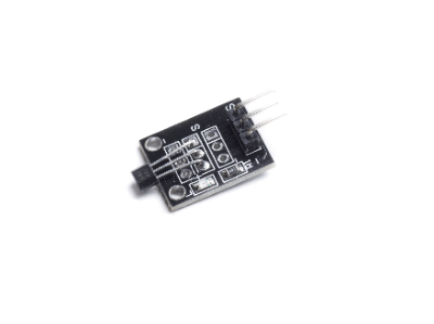
A magnetic sensor is a device that detects magnetism and is used to detect magnetism and geomagnetism generated by a magnet or an electric field. Magnetic sensors can detect the vector (magnitude and direction) of magnetism.

Magnetic sensors can be broadly classified into Hall sensors using Hall elements and magnetoresistive element sensors using magnetoresistive elements (MR). Hall sensors measure the Hall voltage generated by the Lorentz force in a vertical magnetic flux on the element, whereas MR sensors measure the ohmic resistance generated by the Lorentz force in a horizontal magnetic flux on the element.

Uses of Magnetic Sensors

In recent years, air sensors have been used in a wide range of applications, from consumer products to industrial equipment.
A typical example is smartphones. They are used for direction detection in mapping and orientation applications.

Also, in the industrial and research fields, they are often used to inspect and detect substances that generate magnetism. Examples of detection targets are listed below.

  • Detection of geomagnetism generated from the earth
  • Magnetic detection of minerals in the bedrock
  • Detection of biological magnetism generated by muscles and brains
  • Magnetic ink detection to prevent counterfeiting of banknotes
  • Magnetic detection is used for non-destructive testing of structures
  • Magnetic flux detection produced by electric currents

Detection of the above can be applied to the following products

  • Compasses
  • Rotation and angle sensors
  • Magnetic flux sensors for MRI using biomagnetic flux
  • Non-contact ammeter

Principle of Magnetic Sensors

Magnetic sensors detect magnetic vectors (magnitude and direction) by converting Lorentz forces due to magnetic flux into electrical signals.
Different types of magnetic sensors can be broadly classified into Hall sensors using Hall elements and magnetoresistive element sensors using magnetoresistive elements (MR).

1. Hall sensors

Hall sensors detect magnetic vectors using the Hall effect between a Hall element and a perpendicular magnetic flux. The Hall effect is a phenomenon in which an electromotive force is generated at 90 degrees to the magnetic flux and current when a current perpendicular to the magnetic flux is generated.

2. MR Sensor

MR sensors detect magnetic vectors using magnetoresistive elements whose resistance changes when they sense magnetism.
There are four types of magnetoresistive elements: semiconductor magnetoresistive elements, isomeric magnetoresistive elements, giant magnetoresistive elements, and tunnel magnetoresistive elements.

Other Information on Magnetic Sensors

1. Magnetic Sensors and Compass

A compass is a tool for determining direction. Permanent magnets have been used since ancient times, but in recent years electronic compasses, which use magnetic sensors instead of permanent magnets to calculate the direction, have become popular.

Electronic compasses are also found in smartphones. Its role within a smartphone includes direction detection by azimuth apps and navigation with map apps.

Most map applications use GPS, but the accuracy of GPS position detection is only a few meters. Therefore, it is not sufficient for navigation. In addition, GPS signals may not be received in areas with poor reception.

To solve these problems, the system is combined with an electronic compass to detect azimuth and direction of travel and compensate for GPS errors. It is also possible to adjust the map display so that the direction of travel always points upward.

Note that because the electronic compass calculates azimuth from weak geomagnetic fields, it also uses technology to compensate for the effects of magnetic parts such as speakers.

2. Magnetic Sensors and Automobiles

Various sensors are used to realize control systems that enhance the safety and comfort of automobiles, and magnetic sensors have advantages in terms of reliability and cost. They are mainly used in the following applications.

  • Vehicle speed detection
  • Engine speed control
  • ABS (Anti-lock Breaking System)
  • Power steering
  • Car navigation

In recent years, automated driving technology has been attracting attention, and technological development is progressing toward realization using AI technology. While there are still many issues to be addressed, magnetic marker systems are attracting attention as a way to solve these problems.

Unlike fully autonomous automatic driving, magnetic marker systems are guidance-based systems. It refers to a driving support system that uses a vehicle’s magnetic sensors to detect magnetic markers placed on the road, identify the current location, and control the vehicle’s path. Demonstration tests have been started to realize automated driving on route buses.

カテゴリー
category_usa

Functional Tester

What Is a Function Tester?

A function tester is a device used to verify the functionality of electronic boards, ensuring they operate as intended. It is critical in electronic control systems across various devices, where the first step towards guaranteeing safe and correct operation is to inspect the electronic board for defects.

Inspection methods include AOI (automated optical inspection), ICT (in-circuit testing), and FCT (functional circuit testing), with AOI focusing on visual checks for wiring and component integration defects.

Uses of Function Testers

Function testers assess if an electronic board functions correctly by simulating operational conditions and checking for the correct output signals and component operations. Given the unique functionality required by each board, selecting an appropriate tester is crucial. Applications range from testing power supply boards for correct voltage and current output to evaluating LED lighting efficiency in response to input current.

Principle of Function Testers

Function testers work by supplying power and input signals to the board, and then measuring output signals and component behavior against expected outcomes. This process often involves using test patterns generated by FPGAs to stimulate microcontrollers and ICs on the board. Before testing, a visual inspection is recommended to identify any potential defects that could lead to board damage during testing.

Unlike ICT, which focuses on the electrical characteristics of individual components, function testing evaluates the board’s overall operational capability.

Other Information on Function Testers

1. Difference From In-Circuit Testing

In-circuit testing primarily checks for correct component placement and soldering, not evaluating functional performance or internal connections like BGAs. Function testers, however, are designed to identify functional failures, with many models incorporating ICT capabilities for comprehensive evaluation.

2. Examples of Actual Function Test Items

Functional tests may include assessments of current and voltage in output circuits, LED operation, microcontroller functionality via FPGA-generated patterns, and connector integrity. With the increasing complexity of electronic circuitry in devices like smartphones and automotive controls, custom testing solutions, including peripheral circuits and electromagnetic shielding, are often required.

カテゴリー
category_usa

Pressure Sensor

What Is a Pressure Sensor?

Pressure Sensors

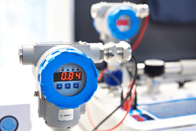
A pressure sensor is a device that measures the pressure of a gas or liquid. The measuring section converts change caused by pressure into an electrical signal and outputs the pressure. The typical measuring part is a gauge type.

Semiconductor gauges, strain gauges, and thin metal films are used for gauge-type pressure sensors. Some types can be set to atmospheric pressure, absolute pressure, or an arbitrary standard for the pressure at the time of measurement.

Uses of Pressure Sensors

Pressure sensors are used in many industrial processes to measure pressure in piping and equipment.

It is necessary to select an appropriate pressure sensor in consideration of the pressure range, the type of gas or liquid to be used, the temperature at which it will be used, and its durability. Pressure sensors are used in a variety of applications, as shown below.

  • Measuring the pressure of liquids in liquid filling equipment
  • Pressure measurement of liquids and gases flowing in pipes in plants
  • Pressure measurement for pressure control in equipment that uses substances highly reactive to pressure
  • Application to pressure sensor mats
  • Applications in automobiles, industrial machinery, aerospace, medicine, etc.

Principle of Pressure Sensors

Gauge-type pressure sensors measure pressure by detecting diaphragm deformation. There are several types of detection methods, such as semiconductor gage type, strain gage type, and metal thin film type.

Four gauge resistors are placed on the surface of the diaphragm, and when the diaphragm is deformed by pressure, the electrical resistance value changes. 4 gage resistors are assembled in a bridge circuit to output the resistance change as a voltage.

1. Semiconductor Gauge Type Pressure Sensors

Semiconductor gauge pressure sensors use a semiconductor itself as a diaphragm and measure pressure using the piezoelectric effect, which is the property of a semiconductor that changes its electrical resistance when it is subjected to pressure. The change in resistance in response to pressure is much greater than in other methods, and the semiconductor pressure sensors are characterized by the high durability of the device because a robust diaphragm can be made.

2. Strain Gage Type Pressure Sensors

In the strain gauge type pressure sensors, a strain gauge is attached to the backside of the diaphragm, and the change in gauge resistance is measured. The strain gauge is a device that measures strain by utilizing the property of a metal that electrical resistance changes when it is deformed.

3. Metal Thin-Film Type Pressure Sensors

The metal thin-film type pressure sensors measure pressure by forming a metal thin-film on a diaphragm and measuring the change in electrical resistance of the deformed metal thin-film due to pressure. They are highly sensitive to strain gauge type and can be used under high temperatures. 

4. Pressure Sensors Other Than Gauge Types

In addition to the gauge-type pressure sensors, there are other types of pressure sensors, such as capacitance type, optical fiber type, and vibration types.

The capacitance type detects the capacitance between a fixed electrode and a diaphragm electrode. The amount of displacement of the diaphragm, which deforms in response to changes in pressure, is measured as a change in capacitance and converted to pressure. It is suitable for measuring the pressure of multiple gas types or gas mixtures.

In the optical fiber type, when pressure is applied to the diaphragm, the diffraction grating at the tip of the optical fiber is deformed, and the change in wavelength of the reflected light is measured. It can measure high temperatures and high precision and is used to measure the pressure of molten resin and blood pressure inside the body.

In the vibration type, a transducer is installed in a silicon diaphragm chip, and when the diaphragm is deformed by pressure, the natural frequency of the transducer changes. The change in frequency is detected and converted to pressure. It has features such as high accuracy, high sensitivity, and high resolution.

Pressure Sensors Application Examples

1. Pressure Sensos Mat

One example of a pressure sensor application is a pressure sensor mat. The pressure sensor mat is generally in the form of a thin mat and intended to be laid on the floor, etc.

Examples of applications of pressure sensor mats include the detection of entry into a high-security room or entry into a hazardous area in a factory. If an entrant steps on the pressure sensors mat, the pressure sensors can sound a buzzer or turn on a lamp based on the information it detects.

In addition, by installing pressure sensor mats in rooms of facilities or at the entrances of homes, it is possible to know when a person with dementia is about to leave.

2. Pressure Sensors for Automobiles

Automotive pressure sensors are used as sensors to precisely measure the pressure of liquids and gases to improve fuel efficiency and other factors. Since pressure sensors used in automobiles are compact, highly accurate, and used in harsh operating environments, semiconductor gauge pressure sensors using piezoresistors are widely used.

Automotive pressure sensors are required to operate reliably and accurately over the long term in operating temperatures ranging from -30°C to 150°C, and even exceeding 300°C depending on the location of use. In addition, since diesel engines must compress a mixture of fuel and air at very high pressures, pressure sensors must have the ability to accurately measure pressures as high as 200 MPa. 

カテゴリー
category_usa

Optical Power Meter

What Is an Optical Power Meter?

An optical power meter measures the intensity or power of light, particularly in fiber-optic communications. It may also be referred to by other names, such as a laser power meter, irradiance meter, photometer, or illuminance meter, based on the light type and measurement units involved. Despite the varied terminology, all these devices serve the fundamental purpose of quantifying light’s physical intensity.

Uses of Optical Power Meters

Optical power meters precisely measure the absolute light intensity from various sources, including optical fiber communication wavelengths, lasers, and LEDs. They are essential for ensuring the safe and efficient use of light sources, especially in preventing harm from overexposure to intense light, which can be hazardous to living organisms, including eye damage.

Principle of Optical Power Meters

Optical power meters utilize sensors such as photodiodes and biosensors that employ the photoelectric effect to translate light intensity into measurable physical values like current or temperature changes. These devices typically feature a semiconductor sensor to detect light intensity and an indicator for result display. Calibration at specific wavelengths is crucial for accurate measurements due to the sensors’ varying efficiency in converting light intensity based on the wavelength of received light.

Other Information About Optical Power Meters

1. About the Optical Wavelengths Handled by Optical Power Meters

While optical power meters measure light intensity, they do not measure wavelengths directly. Users must set the measurement wavelength, and the device uses a corresponding calibration. Meters often support selectable wavelengths, catering to applications from Blu-ray and DVD production to optical fiber communications, with popular ranges including 400 nm to 700 nm for visible light and 1,300 nm to 1,550 nm for fiber optics.

2. Points to Keep in Mind When Measuring Optical Power

Choosing the appropriate optical power meter for the wavelength of interest is crucial for accurate measurements. Photodiodes, based on the photoelectric effect, vary in their wavelength handling capabilities; for instance, InGaAs photodiodes cover 800 nm to 1,700 nm, suitable for near-infrared through certain fiber optic communication bands, whereas Si-based photodiodes are better for visible light. Consistency in measured wavelengths, stable temperature, and a vibration-free environment are vital for reliable evaluations, especially in optical fiber communications where wavelengths can vary with temperature and mechanical stress.

カテゴリー
category_usa

Image Processor

What Is an Image Processor?

An image processor is a device that processes images taken by a camera or other device to measure and analyze the characteristics of an object based on the images.

Such image processing is performed on a computer, and the results of the analysis can be reflected in other equipment.

Image processing devices make it possible to recognize the shape of objects, measure distances, and count the number of pieces. By feeding this information back to other devices that combine this information, automation of all kinds of objects becomes possible.

Uses for Image Processors

Image processing equipment is used in a wide range of applications, from everyday life to industrial and medical fields.

  • Quality inspection and counting of parts in factories
  • Clarification of images from surveillance cameras
  • Driving assist and automatic driving systems
  • Diagnostic assistance from medical images such as X-rays and CTs
  • Face recognition systems for smartphones
  • Measurement systems for the number of people at train stations and commercial facilities

In recent years, IoT technology combined with human intelligence and machine learning has also been actively developed to automate and improve the efficiency of various human activities.

Principle of Image Processors

Although there are various types of image processing devices depending on the application, they are basically composed of a camera and a computer.

After images captured by the camera are transferred to the computer, they are pre-processed for image processing. What exactly is done depends on the application.

For example, when measuring the number of subjects, filter processing is used to remove noise, sharpen the image, and make it binary in order to extract the characteristics of the subject. This produces an image in which the areas where subjects exist are set to 1, and the areas where they do not exist are set to 0 and can be treated as a matrix with only 0s and 1s as elements.

This matrix can then be used to measure the number of objects by segmenting each object using kernel processing, etc.

Using packaged image processing software, a variety of processes, including these, can be performed.

In recent years, attempts have also been made to increase the accuracy of analysis and feature extraction by combining these existing image processing software with machine learning and AI technologies.

Industry Trends in Image Processors

In the history of manufacturing, there has always been a need for systems that automate without human intervention, and this has evolved in the field of factory automation (FA), the automation of production processes.

In recent years, with the dramatic advances in image processing technology, the role of these systems has become increasingly important, not only in replacing workers with machines but also in production control systems to improve productivity and quality and reduce costs. Image processing systems that combine cameras and sensors with image processing equipment play a central role in this process.

Due to the global labor shortage and the growing need for safety in food and other products, inspection systems combining manpower-saving systems with image processing systems are becoming increasingly important in the automotive, food, pharmaceutical, and cosmetics-related fields. In addition, further improvements in image processing and sensor technologies have expanded the range of inspection capabilities, and the visual inspection business combining image processing systems and deep learning is gaining momentum.

One area of future focus is image sensors that utilize smartphones. With the addition of attachments and applications, smartphones can easily be used as image processing devices to read barcodes and inspect text. Since they can be easily integrated with e-commerce, they are expanding not only into the manufacturing industry but also into the logistics and retail sectors.

Image Processing Software

Image processing software used in inspection and quality control used to be developed by creating specifications and designing from system requirements when building a system, but as the processing capacity of image processing equipment has improved and the types and packages of highly versatile inspection software have become abundant, image processing software can be freely combined and used. However, as the processing capacity of image processing equipment has improved and the variety of versatile inspection software types and packages has increased, it is now possible to freely combine and utilize such software.

Packages include, for example, shape, area, color, position, and flaw determination, as well as combined length, angle, and diameter measurement software.

More recently, image processing software employing deep learning has been used to enhance recognition capabilities by allowing the software to learn in the same way as humans, and is being introduced as a replacement for tasks that were previously performed by visual inspection.

For example, it is now possible to distinguish scratches from defects in more detail, and in character recognition, it is now possible to improve the accuracy of recognition of handwritten characters.

In the field of medicine, it is now possible to detect and treat diseases that are difficult to detect with the human eye, and in the field of crime prevention, it is possible to identify individuals from images captured by security cameras.

カテゴリー
category_usa

Cam Positioner

What Is a Cam Positioner?

A cam positioner is a device used in the fields of mechanical engineering and automatic control.

They are intended to replace mechanical cams and simplify their structure. A mechanical cam is a mechanism that rotates a circular or elliptical cam shaft to operate a part that performs a specific action based on its shape.

Cam positioners typically use a sensor or encoder to detect the angle of rotation or position of the shaft and feed it back to a control system. The control system controls the shaft based on a pre-set cam profile.

In other words, the cam profile can be set as a profile in the cam positioner to replace a conventional mechanical cam. This avoids the complex mechanisms of mechanical cams and simplifies the structure.

Uses of Cam Positioners

1. Automotive Industry

The are used in engine valve control, offering precise timing and valve opening/closing control for engines, thereby improving fuel efficiency and reducing emissions.

2. Machining

They are used in machining equipment, such as machine tools like lathes and milling machines to control accurate positioning and cutting movements of tools.

3. Assembly Line

Used in product packaging and assembly lines. Accurate position control allows product packaging and assembly operations to be performed quickly and accurately.

4. Robotics

Used in robotics and automation systems. Cam positioners may be used in motion control and positioning of robotic arms.

5. Printing

Cam positioners are also used in the printing process. They are used to control the position of the print head and ink supply.

Principle of Cam Positioners

A cam positioner consists of elements such as measurement by a sensor, information processing by a control system, and position control by an actuator. This enables precise control of the position and speed of the axis to achieve the desired motion.

1. Sensor or Encoder

Cam positioners use sensors or encoders to measure the angle of rotation and position of the axis. This detects the current state of the axis and provides feedback to the control system.

2. Control System

Cam positioners work in conjunction with a control system. The control system receives feedback information from the sensors and encoders and calculates the difference from the target axis rotational position and speed.

3. Actuator

The control system sends commands to actuators to control the position of the axis. The actuator may take the form of an electric motor, hydraulic cylinder, or pneumatic cylinder. The actuator moves the axis to a precise position based on commands from the control system.

4. Feed-Forward Control

Feed-forward control may also be used with cam positioners. Feed-forward control uses position and velocity information predicted in advance based on a profile to control the actuator. This minimizes the effects of delay and response time and allows for more accurate control.

Types of Cam Positioners

The main types of cam positioners are as follows:

1. Optical Cam Positioner

An optical sensor is used to detect the convex position of the cam. The optical sensor detects the reflection or transmission of light between the cam and the convexity of the cam to obtain position information.

2. Laser Cam Positioner

Uses a laser sensor to detect the position of the cam’s convexity in a non-contact manner. The position information is obtained by analyzing the reflection or scattering pattern of laser light.

3. Encoder Positioner

Uses a device called an encoder to detect the angle of cam rotation. The encoder generates a pulse signal in response to cam rotation to acquire position information.

4. Potentiometer Positioner

A variable resistor called a potentiometer is used to detect the position of the cam. The resistance value of the variable resistor changes with cam rotation to acquire position information.

カテゴリー
category_usa

Low Frequency Module Oscillator

What Is a Low Frequency Module Oscillator?

A low frequency module oscillator is a device that generates a relatively low frequency signal.

The definition of the term “low frequency” itself varies depending on the field in which it is used. However, the specifications of low frequency module oscillators sold in the market range from a few Hz to several hundred kHz. Oscillator circuits can be used to generate AC signals of specific frequencies, and are generally used to generate reference signals for testing using frequency signals.

Signals in the range of approximately 20Hz to 20kHz that can be produced by oscillators are in the audible range and can be heard by humans as sound when amplified.

Uses of Low Frequency Module Oscillators

The most common use of low frequency module oscillators is to analyze the frequency response of audio equipment. Since most electronic devices that use frequency signals for communication use radio frequency (RF), and the familiar low frequency is sound waves, acoustic devices are the most common circuits that use low-frequency signals.

For example, an audio amplifier is used as a DUT (Device under test), and the input signal is generated by a low frequency module oscillator. By analyzing the output signal with an FFT analyzer, it is possible to assess the characteristics of the amplifier under test.

Principle of Low Frequency Module Oscillators

The principle of the low frequency module oscillator lies in the technology of generating a stable frequency signal based on an oscillator circuit. Since it is difficult to realize low-frequency waveforms with the well-known Hartley or Colpitts type oscillator circuits based on LC resonant circuits due to wavelength limitations, RC (or CR)-type oscillator circuits are used.

RC-type oscillators include Wien bridge circuits, bridged T-type circuits, and state-variable-type circuits, all of which can achieve oscillation by adjusting the amount of amplifier feedback. Of these, the Wien bridge circuit is the most well-known and widely used, partly due to its simplicity of having only one amplifier in the circuit.

On the other hand, the state-variable-type provides lower distortion and two-phase output. A variable resistor or a variable capacitor called a varicap may be used to control the frequency. Step-variable with capacitors and fixed resistors is another example of a frequency determination technique.

An RC oscillation circuit alone cannot produce a sine wave with a constant amplitude. Therefore, a device to control the amplitude is usually required. There are methods such as using an element whose resistance changes with the applied voltage, such as a light bulb or thermistor, to adjust the feedback amount, or assembling an electronic circuit that detects the voltage at the output to adjust the feedback amount.

Other Information on Low Frequency Module Oscillators

1. Self-Made Electronic Circuit Kits and PC Software

Low frequency module oscillators are relatively familiar electronic circuits, and the resulting devices can be used to create buzzers for home use, for example. For this reason, they are widely used in home-built electronic circuit kits and as educational materials for students learning electronic circuits.

Free software (e.g., WaveGene) that can generate low-frequency sound sources on Windows PCs is also widely available.

2. Accuracy and Calibration of Low Frequency Module Oscillators

In general, the frequency accuracy of RC oscillators is not as good as that of crystal (quartz) or ceramic oscillators. This is due to variations in resistance and capacitance values, as well as changes in the RC value depending on temperature.

However, compared to crystal (quartz) oscillators, RC oscillators are relatively inexpensive and easy to configure. As a result, they are widely used, and there have been some innovations to improve the accuracy of RC oscillators. A typical method for improving accuracy is calibration. Calibration is a widely used method that utilizes digital circuits, and frequency values are adjusted by calibration especially before shipment.

Calibration using digital circuits is based on a method that compares the frequency with an internal clock and corrects it. For example, a certain value of a memory address is commonly used for calibration purposes. This can be done by changing the value of a register called OSCCAL in the operation of the digital circuit, and automatically selecting the register value that will result in the desired oscillation frequency.

カテゴリー
category_usa

AC Servo Motor

What Is an AC Servo Motor?

Servo Motors

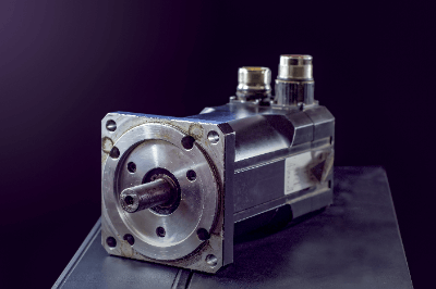
An AC servo motor is an actuator that converts electrical signals into physical motion. The servo in a servo motor means to move faithfully and as commanded.

The motor is designed to achieve accurate rotational position, speed, and force through electrical control.

There are three types of motors: DC motors, AC motors, and pulse motors, AC servo motor is classified as AC motors. Most of the motors currently used in the factory automation (FA) field are AC servo motor motors.

Uses of AC Servo Motors

AC servo motors are used when physical work is required in automation systems. They are especially used in the production of industrial products that require a high degree of precision.

For example, industrial robots used in automobile manufacturing plants use AC servo motors as moving parts to perform welding and painting operations.

Other applications include semiconductor and LCD manufacturing equipment, electronic component mounting, and LED manufacturing, where AC servomotors contribute to high productivity and high-precision positioning. In familiar situations, they are also used in platform doors at railroad stations and moving parts of medical equipment.

Principle of AC Servo Motors

360_Servo-Motors_ACサーボモーター-1.png

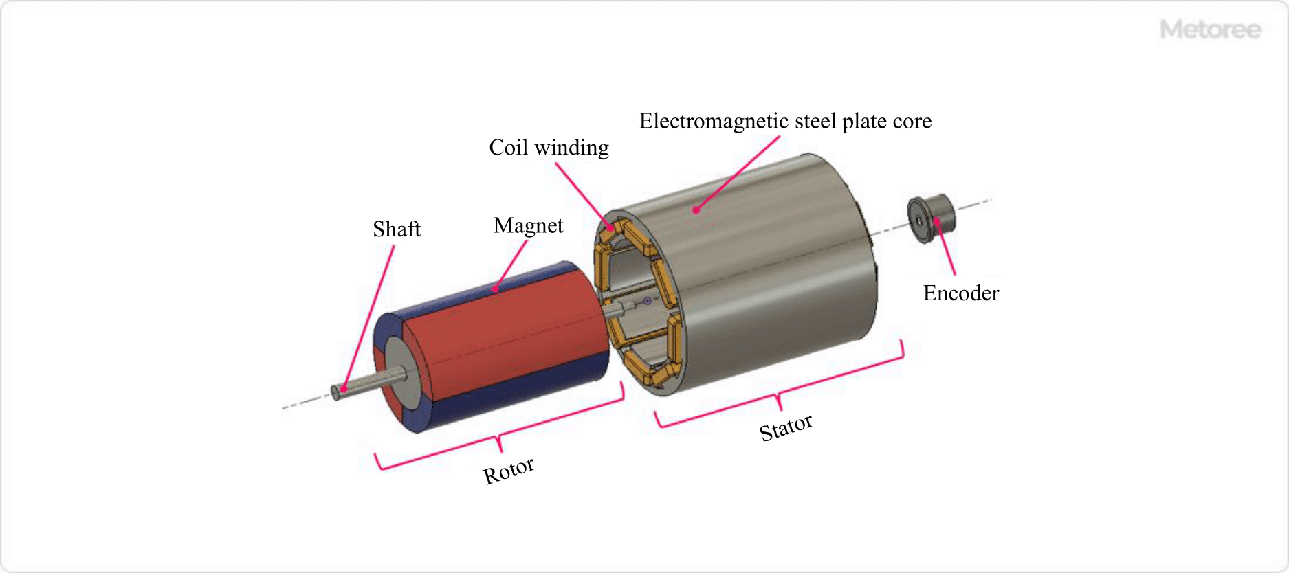
Figure 1. Structure of AC servo motor

The rotor, the rotating part of the motor, is made of permanent magnets and is connected to a shaft and a rotation detector (encoder).

Surrounding the rotor is the stator, which consists of an iron core with wires wound around it. The motor is driven by applying the appropriate current to these wires.

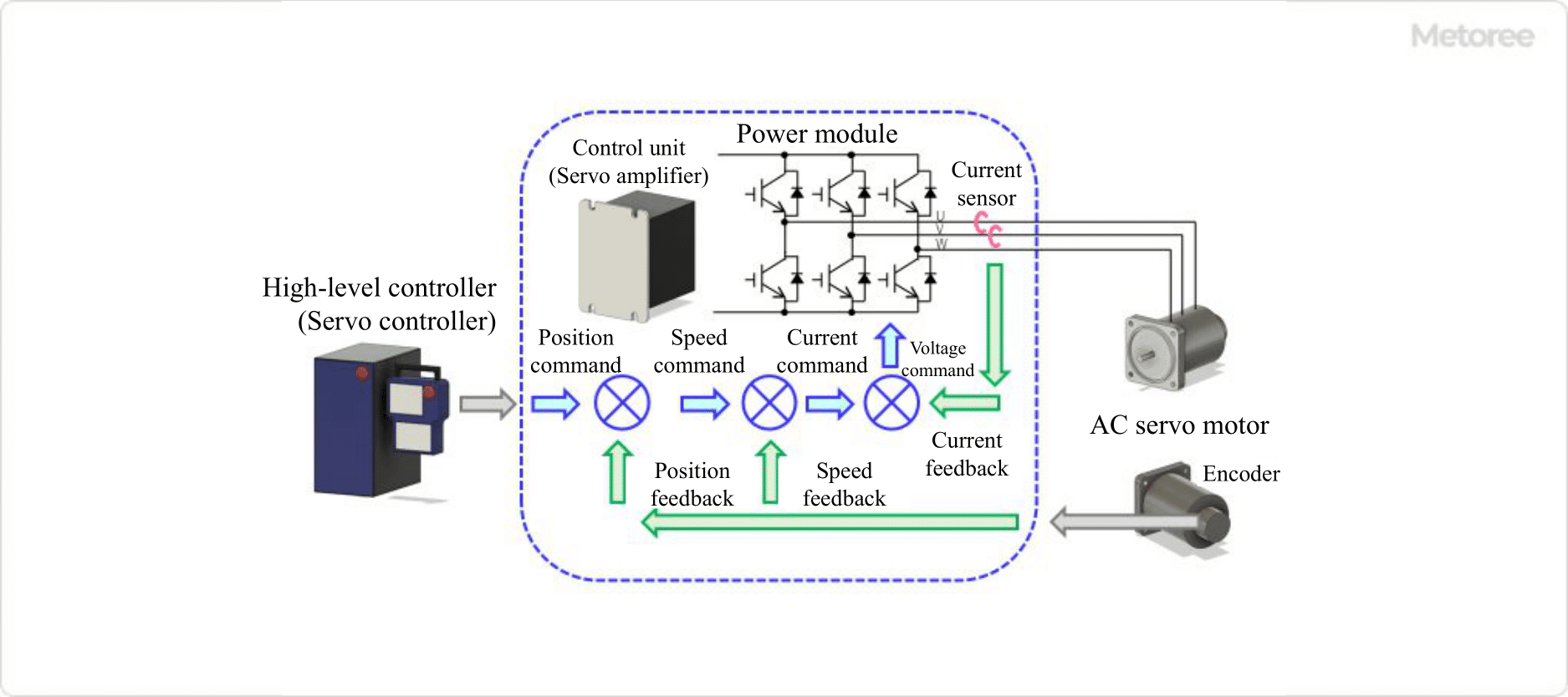
In actual operation, the servo controller first sends a command signal to the servo amplifier, which is the control unit. The accuracy of the AC servo motors is achieved by a detector on the motor that detects movement and sends a feedback signal to the servo amplifier. By comparing the signal from the controller with the feedback signal, the servo amplifier supports the accurate operation of the motor.

360_Servo-Motors_ACサーボモーター-2.png

Figure 2. Control of AC servo motor

Other AC Servo Motors Information

1. AC Servo Motors and Stepping Motors

There are various types of motors, and different types of motors need to be used for different applications and conditions. This section describes the features of AC servo motors and stepping motors, which are commonly used for industrial applications.

Both types of motors are capable of high-precision positioning control, but each has its characteristics in terms of structure and principle of operation.

Stepping motors
Stepping motors, also known as pulse motors, are motors that move by step angles in response to pulse signals.

Since the rotation angle is determined by the number of pulses, accurate positioning is possible. Rotation speed is proportional to the speed of the pulse signal. Because they are compact and generate high torque, they excel in acceleration and responsiveness, making them suitable for applications that require frequent repetition of start and stop operations.

  • Minimum step angle is about 0.72° in rotation angle (1/5,000@1 rotation)
  • Control is an open loop, and if a step-out occurs, it will not return to the original position.

AC servomotors
AC servomotors are equipped with an encoder, a device that detects rotational speed and position, which is fed back to the motor’s rotational control for accurate positioning.

Servo motors have stable torque characteristics from low to high-speed ranges, making them suitable for applications that require high-speed movement over relatively long distances.

2. Brakes for AC Servo Motors

360_Servo-Motors_ACサーボモーター-3.png

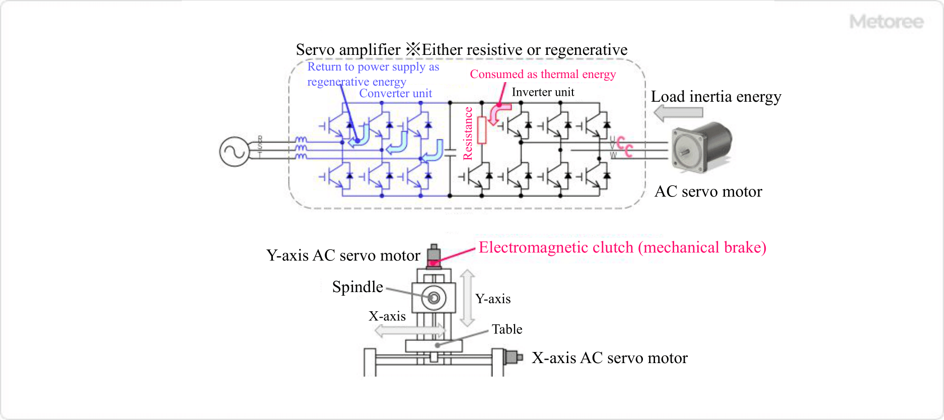
Figure 3. Brake mechanism for AC servo motor

To ensure the safety of industrial equipment such as drives that use AC motors, two main types of brakes can be used to stop the motor in an emergency when the power supply is cut off, or a failure occurs.

Brake for braking
One is called a braking brake, in which a large load moment of inertia is either consumed thermally by a resistor or fed back to a servo amplifier as regenerative energy to be reused as electrical energy.

Mechanical brakes
The method that consumes heat is called a dynamic brake, and the method that reuses it as electrical energy is sometimes called a regenerative brake. Both are only for deceleration and have no holding function.

To prevent a vertical drive system from falling in the event of a power failure, etc., it is necessary to keep the system at a standstill for a long period, and a holding brake or electromagnetic brake is used for this purpose.

A non-excitation actuated electromagnetic brake is used to apply the brake when the power is cut off and maintain the stopped state.