What Is a Jumper?
 A Jumper is a generic term for a metal wire, metal terminal, or pin that shorts two points on a breadboard or PCB.
A breadboard is a board on which electronic circuits can be built simply by inserting electronic components and jumper wires into the holes. Each of the electronic components that make up a circuit has a specific role, and these components must be connected correctly for the circuit to work properly.
Jumpers make it easy to directly connect two points on a circuit.
Uses of Jumpers
There are two types of jumpers commonly used: one is a conductor type jumper wire and the other is a set of jumper pins and a jumper switch.
1. Jumper Wire
Jumper wires are used to easily build circuits in combination with breadboards. They are useful in electronic construction because they can be used to build circuits simply by inserting components and jumper wires into holes in the breadboard, eliminating the need for complicated soldering.
2. Jumper Pins and Jumper Switches
Jumper pins and jumper switches are two small components that come as a set and are used to switch the circuit operation on the PCB or to expand the functionality of the PCB. The signal connection destination is switched by inserting or removing jumper switches from the jumper pins depending on the application.
This is used not only to switch or expand functions, but also to disconnect circuits with abnormalities. Jumper pins are sometimes called pin headers. A jumper switch is sometimes called a jumper cap.
Principle of Jumper
Jumpers utilize the property that an electric current flows (short-circuiting) when metals make direct contact with each other.
1. Jumper Wire
A jumper wire is a simple metal wire. The ends are often shaped for easy connection to a breadboard. Some are shaped like sockets to connect to jumper pins on the PCB.
Wires other than the connection part are covered with a vinyl sheath. Typical wiring thickness is about 1 mm. If the amount of current to be handled in a circuit is large, thicker wiring may be used to lower wiring resistance.
2. Jumper Pins and Jumper Switches
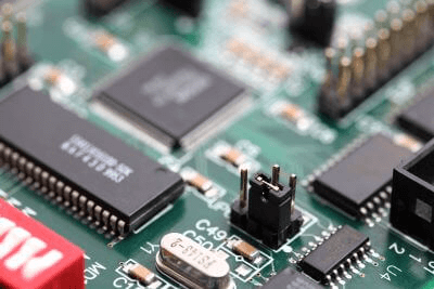
Most jumper pins take the form of metal terminals arranged in a regular pattern with a 2.54mm pitch. There are two types of jumper pin structures: the dip structure, which is suitable for inserting into a breadboard or PCB, and the SMD (Surface Mounted Device) structure, which is suitable for surface mounting on a PCB. These two types are used according to the circuit and PCB design policy.
The metal plug is covered by a plastic outer shell, which makes it easy to connect and disconnect with bare hands. Inside the jumper switch is wiring that shorts the jumper pins when they are inserted into two adjacent jumper pins.
Other Information on Jumpers
1. Precautions for Handling Jumpers
Jumpers are useful for testing circuits and creating experimental circuits because they allow you to easily switch circuit operations and add functions. However, if a jumper is set incorrectly, the operation of the circuit may become unstable or malfunction.
When using jumpers, it is necessary to check the expected circuit behavior and appropriate jumper settings every step of the way.
2. Items on Which Jumpers Cannot Be Mounted
Due to their shape and size, jumpers cannot be mounted on PCBs for consumer devices such as smartphones, which require small size, high density, and low profile. In such devices, PCB designs may be made so that wiring can be switched with 0 Ohm resistors instead of jumpers.
On the other hand, desktop PCs and devices for industrial equipment often have plenty of space, and jumpers are usually installed on the PCB.

 Transfer machinery is a general term for equipment used to move goods and materials.