What Is a Current Limiting Diode?
A Current Limiting Diode is an electronic component that allows a constant current to flow when the voltage is within a specified range. They are sometimes called “CRDs” from the initial letters of the English name “Current Regulative Diode. There are many electronic devices, such as LEDs, that require a constant current during operation. CRDs are used in such electronic devices.
Current Limiting Diodes are generally used for relatively small currents such as 1 mA to 15 mA, but there are also constant-current diodes that can carry large currents such as 500 mA. However, care must be taken to avoid heat generation during operation and consequent damage to components.
Applications of Current Limiting Diodes
Diodes are basic electronic components used in various electronic devices. Some electronic devices require a constant current to flow while being driven. For example, LEDs vary in luminance depending on the amount of current flowing through them, so the amount of current flowing through the circuit must be kept constant in order to stabilize the luminescence. Current Limiting Diodes are used in such current-driven electronic components and devices. Current Limiting Diodes are also used in battery charging/discharging circuits and leakage circuit breakers.
Principle of Constant Limiting Diode
The current characteristics of Current Limiting Diodes are shown in the above figure: from 0 to a certain voltage, the current increases as the voltage increases. However, when the voltage enters a certain range, the current value becomes constant. The current value at this time is called “pinch-off current” and is one of the values that represent the characteristics of Current Limiting Diode.
The voltage at which 80% of the pinch-off current value is given is called the “shoulder voltage,” and a voltage greater than the shoulder voltage must be applied to maintain a constant current. Note that, as shown in the above figure, even a Current Limiting Diode is not a constant current when a large voltage is applied, and the current increases with the increase in voltage again.
Note that applying a voltage so large that it exceeds the constant-current range will damage the diode, so care must be taken when actually using the diode with respect to the size of the voltage.
Types of Current Limiting Diodes
Current Limiting Diodes can operate from voltages as low as 1V to as high as 100V. A variety of low-current diodes are available, including those with different pinch-off current magnitudes and those with reduced pinch-off current value fluctuations. Generally, constant current values of 1 mA to 15 mA are available. On the other hand, Current Limiting Diodes for large currents are also sold, which can provide a constant current of 350 mA or 500 mA.
When using Current Limiting Diodes, care must be taken to avoid heat generation during operation. Heat is generated according to the product of voltage and current, and in some cases this can cause damage to the Current Limiting Diode. In addition, when multiple Current Limiting Diodes with different pinch-off current values are connected, the device may not operate as expected or may be damaged if the circuit is not properly configured.
(Supplement) Types of Diodes
There are many types of diodes. Here we will give an overview of typical diodes other than Current Limiting Diodes.
- Rectifier Diodes
Normally, each household has its own AC power supply, which is used to power electrical and electronic equipment. Except for incandescent lamps, hair dryers, and other devices that operate directly on AC, rectifier diodes are used to convert AC to DC. Rectifier diodes are often used at relatively high voltages, so the forward voltage VF is large, and some can handle large currents, but those for large currents are quite large and require heat dissipation. Rectifier diodes are often used in modules for full-wave rectification, bridge rectification, etc., and are also available as full-wave and bridge modules. - Switching Diodes
These small diodes are mainly used in switching circuits and are enclosed in glass and leaded in appearance. Since they are intended for switching operation, their reverse recovery time trr is shorter than that of rectifier diodes. - Constant Voltage Diode
Diodes are normally used with a forward voltage applied, but Current Limiting Diodes are used with a reverse voltage applied. When a reverse voltage is applied to a Current Limiting Diode, current begins to flow rapidly at a certain voltage. This voltage becomes stable at the Zener voltage (breakdown voltage) and is used as a reference voltage, etc. - Light Emitting Diode (LED)
You are probably familiar with the light-emitting diode, which won the Nobel Prize in Physics in 2014 for the invention of the blue light-emitting diode by a Japanese national. This LED, together with the existing red and green LEDs, now has the three primary colors of light, enabling full-color LEDs and white LEDs, which have dramatically expanded the uses of LEDs. Although this is a recent development in LEDs, LEDs themselves have been in practical use for some time and are regularly used in various devices as power supply indicators, operating status displays, and the like. Indicators for power supply ON and bar-shaped LEDs for signal levels do not need to be excessively bright, but only visually recognizable, so a 10mA current is sufficient for practical use. This kind of usage was not possible with small light bulbs (bean bulbs / wheat bulbs).
Other diodes include laser diodes and photodiodes.

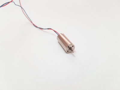 A coreless motor is a small motor without an iron core.
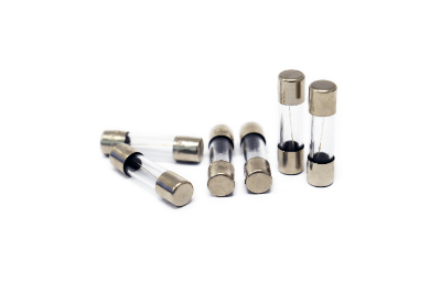 A fuse is an electrical/electronic component that prevents electrical fire or spillover to upper circuits in the event of an overcurrent.
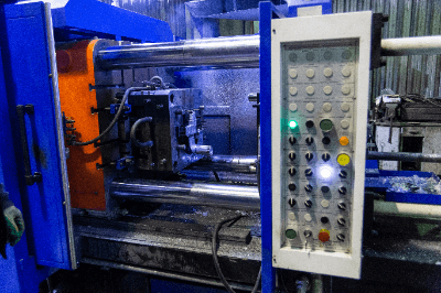
 A diode rectifier is a semiconductor device that rectifies the alternating current of a commercial power supply in a power circuit to obtain a pulsating current.