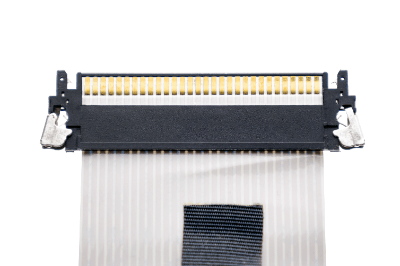
What Is a Flat Printed Circuit (FPC) Connector?
 A flat printed circuit (FPC) connector is a type of connector that is a circuit component.
It connects flexible circuit boards called FPCs. They are not usually seen because they are used to connect circuit boards inside devices.
Usage of Flat Printed Circuit (FPC) Connectors
Flat printed circuit (FPC) connectors are mounted on rigid circuit boards inside electronic devices and used to connect FPCs. Examples include automobiles, medical equipment, cellular phones, notebook PCs, LCD TVs, digital cameras, and game devices.
FPCs and FPC connectors contribute greatly to the miniaturization and space saving of electrical appliances. Demand is expected to increase in the future, as electrical appliances and portable devices tend to become even smaller.
Principle of Flat Printed Circuit (FPC) Connectors
FPC connectors consist of a contact part for connecting electrical signals and a housing part for protecting the contact part. This configuration is similar to that of an ordinary connector.
The material of the contact part is metal. A copper surface treated with gold, silver, or tin is used for good conductivity. To avoid corrosion due to contact between different metals, the same type of metal as the surface treatment of the FPC to be connected is often selected.
Resin is used for the housing portion. Since it is soldered on a rigid board, heat-resistant resin is used for the resin. It covers the contact section and protects the metal terminals from deformation and damage. The contact and housing take a structure that locks the FPC once inserted to maintain the gripping fit.
Structure of FPC Connectors
As mentioned above, FPC connectors have a locking mechanism. There are two types of locking mechanisms: ZIF structure and Non-ZIF (N-ZIF, non-ZIF) structure.
1. ZIF Structure
In the ZIF structure, the FPC inserted into the connector is locked with a lever. When locked, the terminals make contact with each other.
Since less force is required for insertion and friction is reduced, workability and contact problems are less likely to occur even when the number of terminals exceeds several tens of pins. For this reason, it is used in many FPC connectors.
2. Non-ZIF Structure
In the non-ZIF structure, the FPC is inserted into the spring-loaded terminals in a press-fit manner. Since it is a press-fit, the FPC is locked just by inserting it.
Although it is easy to work with because the connection is completed just by inserting, it is not suitable for a terminal count exceeding several tens of pins because of the risk of damaging the connector itself or the FPC due to increased friction.
Types of FPC Connectors
FPC connectors can be broadly classified into four types: two types based on the direction of FPC connection and two types based on the locking mechanism, resulting in the following four 2×2 combinations.
- Horizontal connection ZIF
- Horizontal connection Non-ZIF
- Vertical connection ZIF
- Vertical connection Non-ZIF
There are two connection directions: horizontal and vertical. In the horizontal connection, the FPC is inserted horizontally with the rigid board. In the vertical connection, the FPC is inserted perpendicular to the rigid board.
There are two types of locking mechanisms: ZIF and Non-ZIF. ZIF uses a locking lever to secure the FPC inserted into the FPC connector, while Non-ZIF has no locking lever and uses a spring-loaded metal contact to press the FPC into the connector.
How to Select an FPC Connector
In addition to the aforementioned items, there are other parameters to consider when selecting an FPC connector. It is important to select a component that matches the intended use and the characteristics of the equipment in which it will be mounted.
1. Terminal-To-Terminal Pitch
The distance from the center of an electrode to the center of the adjacent electrode is called the pitch; it is necessary to select a connector that matches the wiring pitch of the FPC.
2. Thickness of FPC
In order to guarantee the stability of the connection and the electrical connection, it is necessary to select a connector that matches the thickness of the FPC.
3. Number of Electrodes
The appropriate number of electrodes must be selected according to the circuit design of the rigid board and FPC.
4. Contact Surface Treatment
From the standpoint of reliability of signal continuity and corrosion protection, connectors should be selected so that the contacts are the same metal as the FPC.
5. Contact Direction
There are three types of contacts with the FPC: top, bottom, and both sides. The appropriate contact direction should be selected in accordance with the structure of the device to be used.
6. Signal Type
A dedicated flat printed circuit (FPC) connector must be selected according to the characteristics of the signal to be passed through the FPC, such as high power or high-speed transmission.