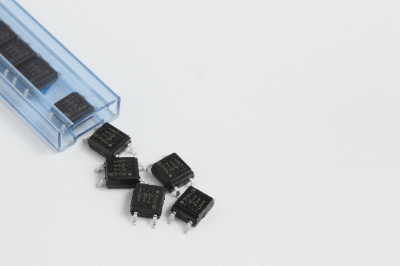
What Is a Solid-State Relay?
Solid State Relays are contactless relays that use semiconductors to transmit input signals to output circuits.
Generally, they are suitable for situations where relays are frequently opened and closed and high-speed response is required since high response and long life can be established.
Applications of Solid State Relays
Solid State Relays are used in situations where the on/off frequency is high, such as in temperature control systems, where their high responsiveness and long life can be maximized.
In addition, unlike general contact-type relays that use magnetic force, there is no mechanical sliding contact. Since no noise is generated by the opening and closing of the contacts, they are often incorporated into products that are vulnerable to noise.
On the other hand, the transmission of signals uses light emission phenomena via semiconductors and diodes. Therefore, there is no small amount of temperature rise effect and the output stage is a semiconductor device. Care must be taken because some parts are not suitable for products with high voltage and high current.
Principle of Solid State Relay
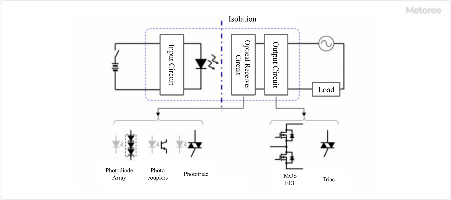
Figure 1. The principle of semiconductor relay
As the relay is said to be contactless, the circuit on the input side is physically isolated from the circuit on the output side, and the signal is transmitted through an opto-isolated device such as a photocoupler.
When an electric current is applied to a light-emitting diode on the input side, the diode emits light, and a circuit on the output side receives the light, and the output circuit operates when the light is detected. Depending on the supplier of Solid State Relays, photodiode arrays, photocouplers, and phototriacs are used for the light-receiving circuit, and variations such as MOSFETs and triacs exist for the output section.
The use of light for signal transmission provides a very fast response. Also, since they do not have mechanical contacts, the contact parts do not wear out, and they generally have a longer service life than contact-type relays.
Other features include the fact that the input and output are completely insulated by an insulating element, so noise generated on the input side is less likely to be transmitted to the output side.
How to Select a Solid-State Relay
First, it is necessary to consider how much responsiveness is required in the circuit where the relay is needed and how often the signal is transmitted. If you do not need such high responsiveness and only low-frequency signal transmission, general contact-type relays are often smaller and less expensive.
If a Solid State Relay is required, also check the maximum current value of its input signal. Since Solid State Relays are output circuits using semiconductors, excessive current flow will damage the semiconductors themselves, rendering them unusable for further use.
Other Information on Solid State Relays
1. Comparison of Solid State Relay and Mechanical Relay
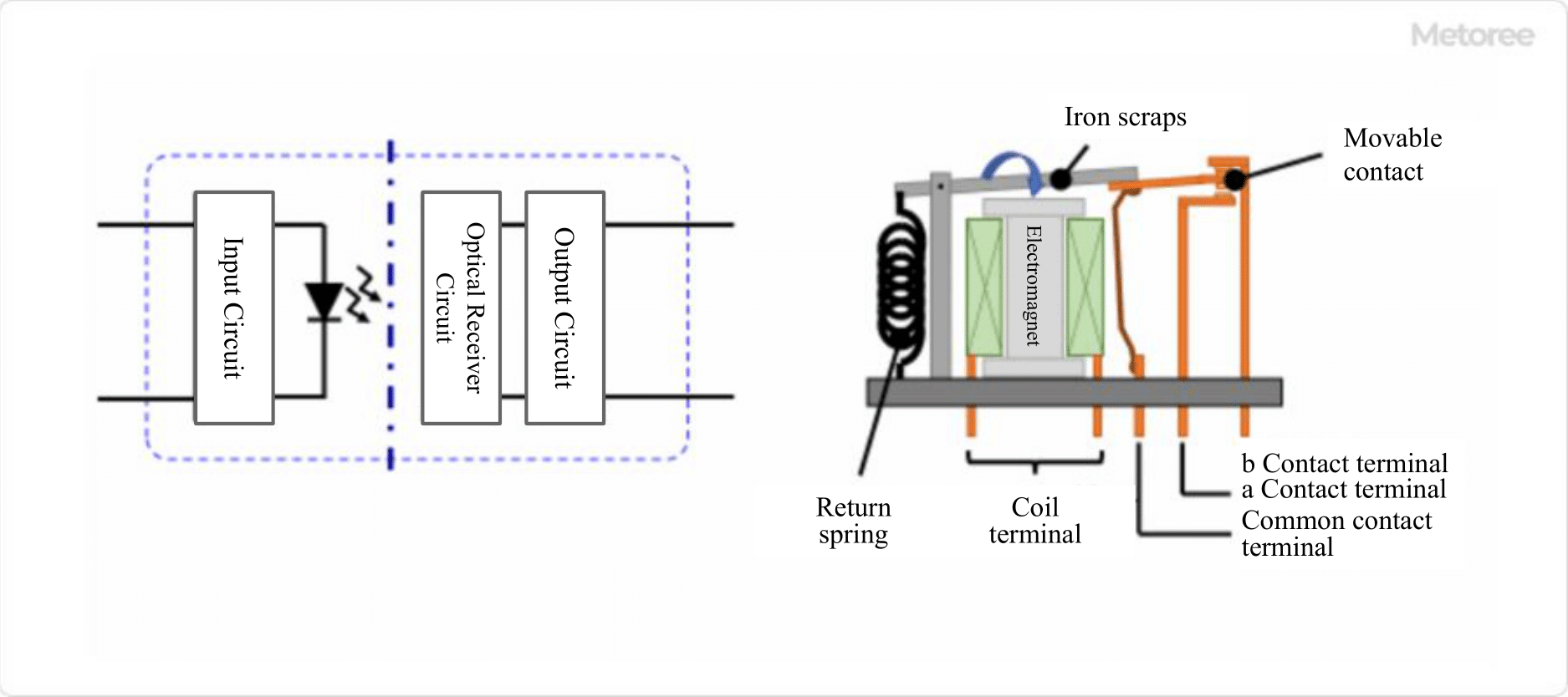
Figure 2. Semiconductor relay and mechanical relay
The difference between a Solid State Relay and a Mechanical Relay is whether they are contactless or contactless types. Semiconductor Relays, also called Solid State Relays, are contactless relays, while Mechanical Relays are contact relays.
Solid State Relays with no contacts are switched on and off by signal transmission only, with no mechanical closing or opening in the electronic circuit. A mechanical relay with contacts has movable parts built into the circuit and uses a coil to generate an electromagnetic force that causes the contacts to make contact and switch ON/OFF.
Solid State Relays and Mechanical Relays each have the following features, which can be used according to your needs.
- Features of Solid State Relays
- Compact and lightweight
- Long life
- Low noise level
- High-speed operation
- High resistance to vibration
- Leakage current
- Low resistance to heat.
- ON resistance
- Features of Mechanical Relays
- High insulation and high voltage resistance
- No leakage current
- Almost no ON resistance
- No operation noise.
- Wear of contacts and breakdown of movable terminals
- Influence of external magnetic field
- Chattering
Solid State Relays have the advantage of being compact and capable of opening and closing at high speeds, and they do not suffer from contact wear and failure as mechanical relays do. On the other hand, mechanical relays have almost no ON resistance, and their strength is that they can be easily used in circuits with high voltage and high power.
2. Solid State Relays for Automotive Applications
Automobiles are equipped with many relays as parts that control the operation of lamps, windshield wipers, audio equipment, motors, blinkers, and so on. In general, mechanical relays have been used for automotive relays.
However, mechanical relays have the disadvantages of limited contact life and large installation space. In recent years, the number of electrically driven in-vehicle devices has been increasing due to the need for low fuel consumption and low power consumption and the multifunctional nature of advanced technology, which has created a need for smaller and lighter relays.
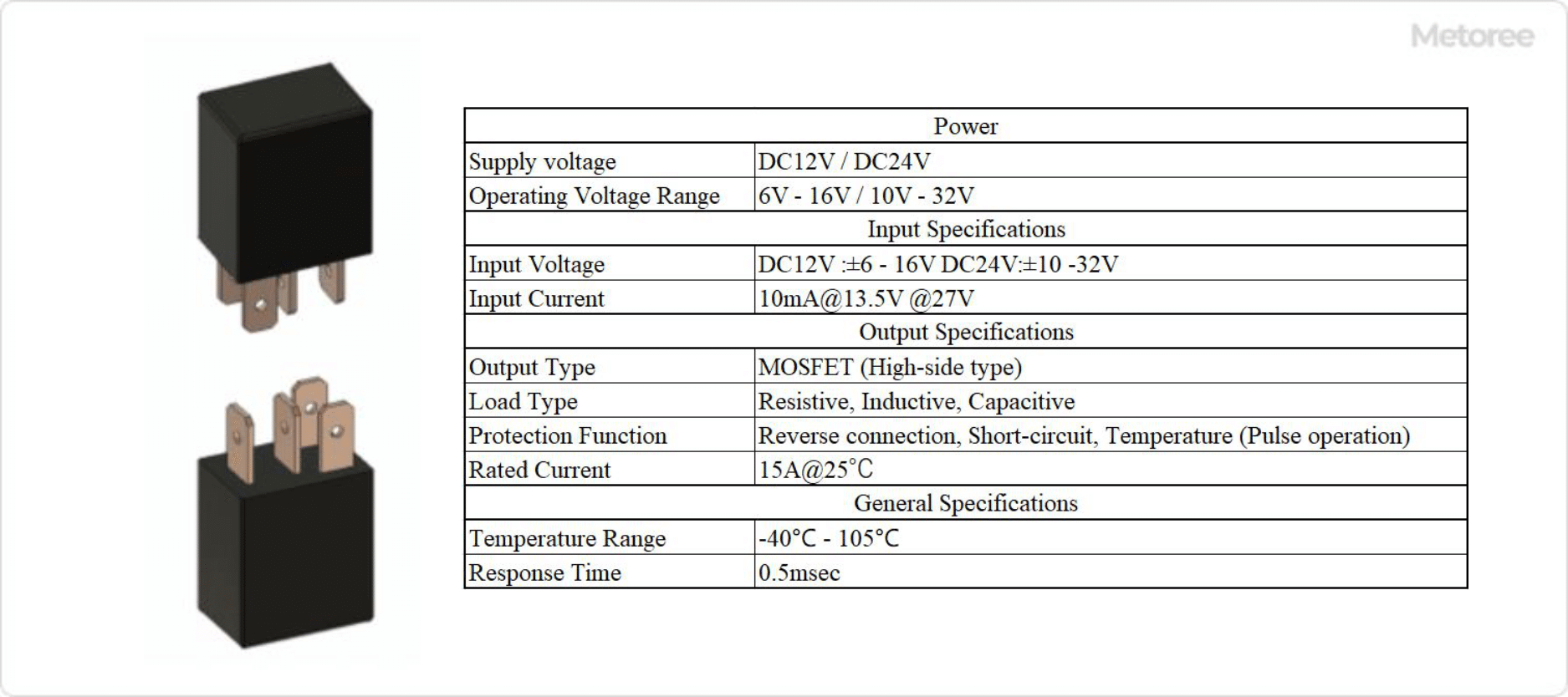
Figure 3. Example of automotive semiconductor relay specifications
Solid State Relays have been developed for automotive applications to overcome the shortcomings of mechanical relays and are gradually replacing them. Figure 3 shows an example of Solid State Relay specifications for automotive applications.
The use of Solid State Relays has made it possible to reduce size and weight, which not only secures space in the vehicle but also contributes to improved fuel efficiency. In addition, the use of high current, which has been a bottleneck, can now be handled thanks to low ON-resistance achieved through advances in semiconductor technology.
 A Liquid Level Sensor is a measuring device used to determine the height of the liquid level in a tank or container, helping to assess the remaining amount of liquid. Some sensors simply detect the presence or absence of liquid, while others can calculate the percentage of liquid remaining by continuously measuring the
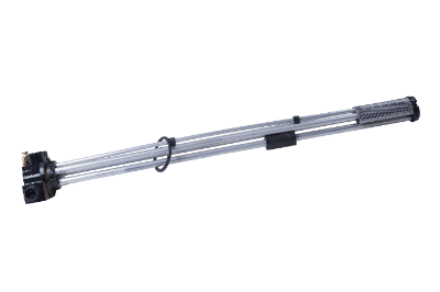
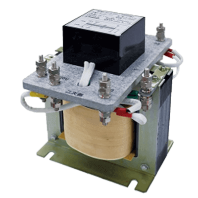 A high-voltage isolation transformer is a device that protects precision electrical equipment and the human body from abnormal voltage caused by large current inflows (lightning surges) due to lightning strikes and power line accidents.