What Is Sludge Disposal Equipment?
Sludge Disposal Equipment is equipment that treats the sludge generated in wastewater treatment and other processes.
In factories and sewage treatment plants, sludge remains during product manufacturing and after wastewater treatment, and must be treated to meet standards. Generally, Sludge Disposal Equipment is used.
There are various types of Sludge Disposal Equipment due to differences in treatment methods, depending on whether the sludge is organic or inorganic. The main principles include the use of microorganisms and dehydration. The equipment is selected according to the type of sludge.
Applications of Sludge Disposal Equipment
A wide range of plants use Sludge Disposal Equipment directly or indirectly, including food processing plants, steel products, chemical products, electronic products, pharmaceuticals, automobiles, paper manufacturing, wastewater from the manufacture of used paper, sewage treatment plants, machine shops, and rolling mills.
Sludge is broadly divided into organic and inorganic. Note that sludge from domestic wastewater and food factory wastewater containing organic matter is organic sludge.
Principle of Sludge Disposal Equipment
Inorganic sludge is generated when wastewater contaminated with inorganic substances is treated. There are many types. For example, in a plating factory, various metal oxides are discharged.
Organic sludge, on the other hand, is generated when wastewater contaminated with organic materials is treated, and is typically generated when biological treatment is performed at sewage treatment plants.
1. Inorganic Sludge
There are several types of inorganic sludge. Sludge such as lime, gypsum, and coal is found in wastewater from ore washing, dust collection, etc. Sludge such as metal oxide powder is found in steel wastewater and collected dust wastewater; sludges of heavy metal hydroxides such as Fe, Al, Cr, Cu, and Ni are found in plating and acid wastewater.
Oil-containing coagulation sludge is also found in wastewater from machinery plants and rolling mills. Flocculated sludge such as sulfate bands and iron salts can be found in wastewater from suspended water treatment at water purification plants.
2. Organic Sludge
There are various types of organic sludge. Activated sludge in food factories occurs in factory wastewater. Organic chemical activated sludge is included in wastewater from organic chemical plants and petrochemical plants.
3. Sludge Treatment
Sludge treatment is easy to transport and is first dewatered to remove water to form a cake. The water content of sludge can be in one of the following states: bound water, internal water, surface-attached water, or free water.
The appropriate dehydrator is selected based on the state of water in the sludge. Free water and surface-added water can be separated relatively easily. Cake-like sludge is dried for metal recovery and reuse, incineration, landfill, or decomposition.
Types of Sludge Disposal Equipment
There are various types of Sludge Disposal Equipment, which may be a combination of equipment. The following are examples of Sludge Disposal Equipment:
1. Various Types of Dehydrators
Sludge is first treated by using a dehydrator to remove water. The sludge that has been dehydrated and concentrated is called cake. There are many types of dehydrators.
Vacuum Dehydrator
The entire drum is immersed in sludge and sewage while the center of the rotating drum is depressurized. The sludge adheres to the cloth on the outside of the drum to be concentrated and made into a cake.
Multi-disc Type Dehydrator
Thin discs and spacers are combined to form a cylindrical filter body, which is rotated and dewatered by combining several of them. The sludge is flocculated with a coagulant and dewatered.
Belt Press Type Dehydrator
This device dehydrates sludge by sandwiching it between two filter cloths. Suitable for dewatering organic sludge.
Filter Press Dehydrator
Sludge is packed into a filter chamber and pressurized for dewatering.
Centrifugal Dehydrator
This device separates solid components in a liquid by centrifugal force. It is capable of separating not only solids and liquids mixed together, but also liquids with different specific gravity.
2. Pressurized Floatation Device
This device is used to separate substances that have a lower specific gravity than water from water. It generates fine bubbles in the water, adsorbs flocculated flocs in the bubbles, and floats to separate sludge.
3. Activated Sludge Disposal Equipment
Microorganisms are grown on the contact material, and the bacteria are directly attached to the sludge. The bacteria capture and settle on the sludge, making it a compact device with high purification capacity.
Running costs can be reduced because there is little excess sludge. Air is fed into the sludge for the microorganisms, and oxygenated Sludge Disposal Equipment is also available to further activate the sludge by feeding oxygen into the sludge.
4. Membrane Separation Activated Sludge Disposal Equipment
In the membrane separation activated sludge process, a membrane with microscopic holes is immersed in an aeration tank to directly filter sewage and separate sludge. The sedimentation tank required for normal activated sludge treatment is not necessary, saving space and reducing treatment costs.
In addition, the treated water is of good quality and microorganisms can be removed, eliminating the need for disinfection.
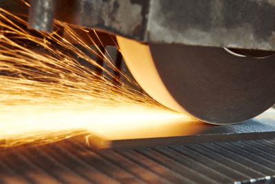 Grinding machinery (
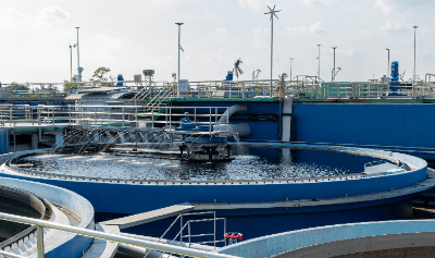 Used wastewater treatment equipment purifies effluent discharged from industry, agriculture, and other industries, as well as from sewage and other human waste.
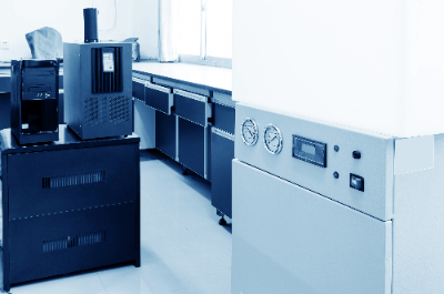 An ultrapure water system is a device that produces ultrapure water. Natural water and tap water contain various salts and organic matter and are not ultrapure. In research and development, these impurities are likely to affect the results of experiments. In the manufacturing industry, impurities in water can affect product quality. Therefore, in these fields, ultrapure water from which impurities have been removed is used.