カテゴリー
category_usa

Bipolar Transistors

What Is a Bipolar Transistor?

Bipolar Transistors

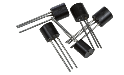
A bipolar transistor is a three-terminal semiconductor device.

Also called a junction transistor, it consists of N-type and P-type semiconductors in a P-N-P or N-P-N junction structure. Unlike field effect transistors (FETs), which are unipolar transistors in which either holes or free electrons act as carriers, bipolar transistors are called bipolar because both holes and free electrons are involved in their operation.

Applications of Bipolar Transistors

The two main functions of bipolar transistors are amplification and switching.

In amplification circuits that turn minute signals into sufficiently large levels, bipolar transistors are more advantageous than unipolar transistors, especially when a high amplification factor is required. Bipolar transistors are also superior in operating at high frequencies.

For example, in power supply regulator circuits where switching noise with high-frequency components must be suppressed, there is a marked difference in noise rejection ratio and other characteristics between circuits using bipolar transistors and those using FETs.

Bipolar transistors are still used in small-lot production and high-frequency amplification circuits that are difficult to make into ICs, but because they are current-driven, they consume more power than unipolar transistors, which are voltage-driven. However, because they are current-driven, they consume more power than voltage-driven unipolar transistors.

On the other hand, switching circuits are used for ON/OFF control of current, but unipolar transistors are superior in terms of switching speed and miniaturization, so they are rarely used for this purpose.

Principles of Bipolar Transistors

Semiconductors can be classified into P-type and N-type semiconductors: P-type semiconductors are filled with holes, which are missing electrons; N-type semiconductors are filled with free electrons, which are in surplus.

Transistors are a combination of P- and N-type semiconductors. In the case of bipolar transistors, there are two types of transistors: one consisting of three regions: P-type, N-type, and P-type, and the other consisting of three regions: N-type, P-type, and N-type.

The former is called a PNP transistor and the latter an NPN transistor; the three regions are the emitter, base, and collector, each of which is connected to an electrode through which voltage is applied and a signal current flows. The base is characterized by being extremely thin.

The principle of operation of a bipolar transistor is explained using the example of an NPN-type transistor, which has an N-type semiconductor sandwiched between a P-type semiconductor.

With the emitter connected to the reference voltage (0V) and the collector connected to VCC (e.g. +5V), when a positive voltage is applied to the base and a base current Ib flows to the emitter, a current Ic of β × Ib flows from the collector to the emitter. This is the principle of amplification by a transistor, which is based on current amplification in bipolar transistors. β is called the current amplification factor and is usually around 100~200. In PNP transistors, the direction of the applied voltage and current is opposite, but the principle of amplification is the same.

In switching operation, a large base current Ib allows sufficient current to flow to the load connected to the collector. Also, if the base current is set to 0A, no current flows to the load. By flowing/not flowing the base current Ib, the current flowing to the load is turned ON/OFF and the switching operation is realized.

Other Information on Bipolar Transistors

Type Names of Bipolar Transistors
Before 1993, the JIS standard stipulated how to name semiconductor components. Therefore, the application of a transistor can be determined to some extent from its type name. For Bipolar Transistors, the first three letters are as follows

  • 2SA: PNP type transistor for high frequency
  • 2SB: PNP type transistor for low frequency
  • 2SC: NPN type transistor for high frequency
  • 2SD: NPN type transistor for low frequency

The actual type name, for example, 2SA372Y, is composed of three letters followed by a number and an alphabet. The numbers start with 11 and consist of 2 to 4 digits, but they are assigned in the order of registration and have no meaning. The last alphabet means the rank classification of the amplification ratio.

This JIS standard was abolished in 1993 but has continued to be used in the standard “Type Names of Individual Semiconductor Devices” issued by the Japan Electronics and Information Technology Industries Association (JEITA), which succeeded it.

カテゴリー
category_usa

Rotary Encoders

What Is a Rotary Encoder?

Rotary Encoders
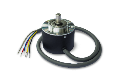
A rotary encoder is a device that measures the amount of movement or angle of rotation of an object to be measured.

Generally, it is attached to the shaft of a motor or reduction gear. They are sometimes attached to servo motors and stepping motors. Rotary encoders are mainly used for rotary devices that require precision control.

Uses of Rotary Encoders

Rotary encoders are widely used in a variety of products driven by motors. The following are examples of rotary encoder applications:

  • Feedback control of industrial robots
  • Control of stage equipment in semiconductor manufacturing equipment
  • Position control of elevators
  • Speed and position control of self-propelled cranes

Rotary encoders are used for rotational position control and rotational speed control. Simple speed control can be achieved with an inverter only. Encoders are useful for precise speed control or for controlling a motor in the middle of rotation.

Principle of Rotary Encoder

A typical rotary encoder uses light to make measurements. It consists of components such as a light-emitting diode, a slit disk, and a phototransistor.

1. Light-Emitting Diode

The light-emitting diode receives power and emits light constantly. The light is focused by a lens and then directed to the slit disk. 

2. Slit Disks

The slit disk is a rotating disk with evenly spaced holes and is fixed to the encoders axis of rotation.

3. Phototransistor

A phototransistor is installed at the end of the light that passes through the holes and emits a pulse wave when the light is received. By measuring this pulse wave, the rotational speed is measured. In addition to light, products that use changes in magnetic force or electrostatic capacitance are also available.

Types of Rotary Encoders

Optical rotary encoders are divided into two types of measurement methods: incremental and absolute. The former measures the relative value of the rotational position, while the latter measures the absolute value of the rotational position.

1. Incremental Type

The incremental type rotary encoder is similar to the above principle, converting light passing through a slit in a rotating disk into a pulse signal and transmitting it. Two types of signals are used to detect the light passing through the slit.

They are generally called A-phase and B-phase. Encoders with a Z-phase signal for home position detection are also available. If there is a malfunction in waveform capturing, the counts will be missed, which is a characteristic that causes errors.

The disadvantage of this method is that the absolute position cannot be determined. However, it is possible to determine the direction of rotation because of the built-in 2-phase signal.

2. Absolute Type

An absolute rotary encoder has a groove on the rotating disk for position information determination. When light passes through this groove, it is detected by the light-receiving element and the absolute position can be measured. Therefore, since absolute position is detected, the direction of rotation can be detected according to the order of the grooves.

In the absolute type, a gray code is generally used for the code of each position. Gray codes, also called alternating binary codes, are a coding method in which adjacent bits change by only one bit. Gray codes are highly resistant to noise and errors and provide high accuracy because they minimize position mis-detection.

How to Select a Rotary Encoders

When selecting a rotary encoder, the measurement method, resolution, and load capacity should be considered.

1. Magnetic Type and Optical Type

There are two types of rotary encoders: magnetic and optical. The magnetic type has excellent weather resistance, while the optical type features high measurement accuracy. Among the optical types, the absolute type has higher measurement accuracy and can detect absolute position. 

2. Resolution

Resolution is the minimum phase that can be measured. The higher the resolution, the higher the measurement accuracy, but it is also more expensive, and the signal may be more complex and less sensitive to noise. Select a resolution that is sufficient to control the machine to which the rotary encoder is to be installed. 

3. Load Capacity

Load is the weight that can be applied to the rotary shaft. If a load greater than the allowable load is applied, the shaft or bearings of the rotary encoder will be damaged. Therefore, select a product with an allowable load that is greater than the maximum load that can be assumed.

カテゴリー
category_usa

Optical Fiber

What Is a Fiber Unit?

A fiber unit is an optical cable section in which light is irradiated using the phenomenon of total reflection of light within the fiber, which forms a double-layered structure with a core with a high refractive index and a cladding with a low refractive index covering the core. It is also called an optical fiber.

In general, fiber units are used to detect various objects as photoelectric sensors that enable the detection of objects by light irradiation by combining a fiber unit that irradiates light while passing it through it with a fiber amplifier that has a light source and an optical amplification function.

Applications of Fiber Units

A fiber unit is a fiber cable equipped with a small sensor head. Generally, a fiber unit is not used by itself but is used in combination with a fiber amplifier equipped with a detection mechanism to enable detection.

Fiber units and fiber amplifiers are widely used in various production sites for non-contact general product detection, detection and positioning of extremely small products in narrow spaces, liquid level detection in storage tanks, and other applications.

Principle of Fiber Unit

Fiber units are optical cables characterized by the fact that light is irradiated using the phenomenon of total reflection of light within the fiber, which forms a double-layered structure consisting of a central core with a high refractive index formed thinly mainly of quartz glass or plastic, and a cladding with a low refractive index covering the surrounding area.

This fiber unit is available in two types: a glass type using quartz glass for the core and a plastic-type using acrylic resin. The quartz glass type is heat resistant, while the plastic type is lightweight and breakage-resistant, and can be matched to the detection environment.

In addition, since the light irradiated from the fiber unit end face spreads at an angle of approximately 60 degrees when the fiber unit’s optical cable is used alone, the purpose of changing this irradiation angle and light collection rate, as well as protecting the fiber unit end face and fixing the fiber unit end face, are also served. A sensor head is also attached to the end face of the fiber unit to protect and fix the end face of the fiber unit.

The fiber unit with these features is used as a fiber sensor by connecting two fibers, one on the light emitting side and the other on the light receiving side, to the light source of a fiber amplifier. A wide range of detection is made possible by the transmission type, reflection type, retro-reflection type, limited reflection type detection methods, and various sensor head shapes.

カテゴリー
category_usa

Safety Relay

What Is a Safety Relay?

Safety Relays

Safety relays are relays used to build safety circuits for machinery and equipment.

Safety Relays have a forced-guide contact structure and are used in the safety-related part of the control system to control the operation of machines only when safety is confirmed. This makes it possible to detect abnormalities and safely shut down equipment accordingly.

The “input section” receives the transmitted signal, determines whether the signal is safe or not, and sends the signal to the “output section. In the module, it plays a central role as the logic section.

Uses of Safety Relays

Safety Relays are mainly used to monitor safety functions. Examples are emergency stops, safety doors, safety mats, and other safety controls. They are designed to detect abnormalities in devices, sensors, or actuators and control them so that machines and equipment can be brought to a safe stop.

By incorporating modules that utilize Safety Relays, it is possible to ensure the safety of machines and equipment. They protect against hazards by detecting potential danger to operators, abnormalities in machinery and equipment, and potential damage.

Principle of Safety Relay

Safety Relays differ from ordinary relays in that they have a forced-guide contact structure with two types of contacts, a and b, each separated by a wall that must be insulated from the other. The b-contacts are interlocked according to the ON/OFF of the coil.

Additional Information on Safety Relays

1. Forced Guiding Contact Structure

The forced guiding contact structure is characterized by a structure that detects abnormal conditions when “if the a contact is welded, all b contacts have a contact gap of 0.5mm or more when the coil is OFF” and “if the b contact is welded, all a contacts have a contact gap of 0.5mm or more when the coil is ON. The structure is characterized by its ability to detect abnormal conditions when “all a-contacts have a contact gap of 0.5mm or more with the coil ON.

Therefore, the a-contact and b-contact are not in the same operating state at the time of contact welding. In the case of a system that controls ON/OFF of a machine, the structure is such that the a-contact is connected to the power control circuit and the b-contact to the monitoring circuit.

By doing so, when the a-contact is welded, the machine will only operate when the coil is in the ON state, and the machine will stop when it is in the OFF state. On the other hand, the bcontact is welded when the coil is in the OFF state, and works as a monitor to detect safety conditions.

2. Emergency Stop Pushbutton Switches

An example of a Safety Relay is an emergency stop pushbutton switch. This system has a safety function in which the contactor opens and closes the motor circuit upon actuation of the switch. If the emergency stop pushbutton is pressed while the motor is running, the motor stops immediately.

The emergency stop pushbutton switch uses NC (normally closed) contacts, which remain closed as long as the switch is not pressed. The system sends a safety signal during this time. When the emergency stop pushbutton switch is pressed, the contact opens and no safety signal is output.

The safety relay module detects the input of a safety signal from the emergency stop pushbutton switch and the pressing of the start switch of the control system, and outputs a signal to the contactor to allow motor operation.

If the safety signal from the emergency stop pushbutton switch is not input to the safety relay in this safety function system, the safety relay module stops outputting the signal to the contactor. This stops the motor.

3. Direct Circuit Operating Mechanism and Forced Guidance Mechanism

Relay circuit actuation mechanisms include the aforementioned forced guide mechanism and direct circuit actuation mechanism. The direct circuit operating mechanism is a mechanism that pulls the NC contacts of the safety switch apart by the force acting on the actuator when the contacts are welded together.

The forced guiding mechanism prevents the NO (normally open) contact and the NC contact from being turned on at the same time, and by monitoring one contact, it is possible to determine if the other is normal.

However, it is not possible to pull the contacts apart as in the direct circuit operating mechanism.

カテゴリー
category_usa

Spindle

What Is a Spindle?

Spindles

A spindle is a rotating shaft.

The original meaning of spindle relates to the shaft used for winding yarn in a spinning machine. However, in engineering, it primarily denotes the shaft that rotates within a machine tool. Tool blades are attached to this axis to perform machining.

When the blade is fixed and the workpiece rotates, such as on a lathe, it is the shaft on which the workpiece is mounted that rotates. The tool blade and workpiece are attached to the end of the shaft, which is sometimes referred to collectively as the spindle. The rotating object itself or the rotating device itself is also called a spindle unit, or spindle for short.

Other uses of spindles include the center shafts of the rear wheels of FWD cars and the front wheels of RWD cars in automobiles, hard disk drives and storage devices such as DVDs in PCs, and parts of water taps.

Uses of Spindles

Spindle is a device that rotates an object with high precision. Tool knives and workpieces are attached to and detached from spindles, causing misalignment between the axis of rotation and the center axis of the workpiece. This misalignment is called runout and is directly related to errors in machining accuracy.

In addition, if the spindle rotation accuracy is poor, the surface quality of the workpiece after machining will also deteriorate, which will affect the appearance of the workpiece. In addition to the rotational error of the spindle itself, a spindle that rotates stably and with minimal misalignment when attaching and detaching tool knives and workpieces is indispensable for precision machining.

Lathes and milling machines are typical examples of machine tools. Lathes use a spindle to rotate the object. Milling machines, on the other hand, use a spindle to rotate the tool.

Principle of Spindles

Since a spindle is a mechanism or device that performs rotary motion, it requires power to generate rotary motion. Electric motors are mainly used to generate the rotary motion, although some spindles also use pneumatic power.

In most cases, rotational speed and torque are controlled by gears or pulleys, rather than by a motor directly connected to the power transmission in order to process the workpiece under optimum processing conditions. Spindles also generally use bearings to maintain stable and high rotational accuracy.

Some spindles use non-contact bearings such as air bearings or hydraulic bearings to further improve accuracy. Since spindles are structured like the rotating shaft of a machine tool, deterioration is inevitable due to vibration and pressure caused by machining. Therefore, it is necessary to maintain a certain level of rotational accuracy at all times through periodic maintenance and parts replacement.

The most common method of inspection is to attach an inspection tool to the spindle, rotate around of a cylindrical object, and compare the difference in roundness.

Types of Spindle

Spindles can be classified into several types according to their drive system, structure, and accuracy.

1. Externally Driven Spindle

This method is used in combination with other power to rotate by an external motor or other power. Also called a pulley spindle. Speed is increased or decreased to a specific rotational speed.

2. Built-in Motor Spindle

The motor and spindle are integrated into a single unit, also called a motor spindle. The shaft of the motor serves as the spindle, making it compact and enabling high-precision machining. It is used in various machine tools and is also used in robot hands.

3. Air Spindle

Air spindles are spindles supported by hydrostatic air bearings or powered by compressed air. Hydrostatic air bearings support spindles without contact, resulting in low bearing loss, quiet operation, and no contamination by oil. They are suitable for applications where oil cannot be used.

Air spindles that use compressed air have the advantages of high rotational accuracy and minimal thermal deformation of the spindle. An air turbine or similar device is used to drive the spindle. The disadvantage is that the rotational speed is easily affected by cutting resistance due to the low torque. Also called air turbine spindle.

Air motor spindles driven by an air motor are used for low-speed applications. It is suitable for high-torque machining at relatively low speeds.

4. High-Frequency Spindle

This is a spindle with a high-frequency motor built into the spindle. It is used to increase rotation speed or to control rotation speed and torque.

カテゴリー
category_usa

Touch Sensor

What Is a Touch Sensor?

Touch Sensors

A touch sensor is a sensor that can detect human touch or approach.

Touch sensors are placed on a transparent film substrate and can be operated by switching or selecting a circuit, such as on/off, when touched by a person.

Since touch sensors do not require strong force to operate and are activated by a light touch, they are used in light fixture switches, automatic doors, elevators, etc.

Touch sensors are used in the same principle as touch panels, which are used in cell phones, PC devices, in-vehicle panels, etc.

Applications of Touch Sensors

Since touch sensors are activated by light force, they are often used as switches for automatic doors and lighting fixtures.

Recently, touch sensors are also used in screens of microwave ovens, refrigerators, and coffee servers in convenience stores.

In industrial applications, touch sensors are used as emergency stop buttons on various machines, security sensors, and seating sensors to confirm whether the user is seated.

Touch panels include cell phones, tablet PC devices, in-vehicle panels, game consoles, and business terminals.

Principle of Touch Sensor

Most touch sensors utilize transparent electrodes made of transparent conductive polymers on a glass substrate.

There is also a type of touch sensor called a transparent sheet touch sensor. There are also two main types of touch sensors: capacitive and resistive.

1. Capacitive Type

Since humans are conductors, bringing a hand close to a sensor causes a change in the electrostatic capacitance of the metal plate of the sensor.
The sensor is activated by the change in capacitance of the electrostatic charge, but it may not respond when gloves are worn.

Capacitive sensors are more responsive than resistive sensors, and capacitive sensors are the most common type of sensor used in smartphones these days.

Generally, the capacitive method can be operated with less force than the resistive method and can support two or more touches (multi-touch) at the same time, so the capacitive method is the mainstream in recent smartphones. The figure below shows the main structure of the capacitive method.

Capacitive type configuration of touch sensor

First, the self-capacitance type calculates touch coordinates using the principle that capacitance increases when a finger approaches the sensor electrode.

Next, the mutual capacitance type calculates touch coordinates using the mechanism that if an electric field is formed in advance between the electrode on the transmitter side (transmitter side) and the electrode on the receiver side (receiver side), when a finger approaches the electrode, part of the electric field is directed toward the finger and the capacitance detected at the receiver electrode is reduced.

2. Resistive Film Method

When pressure is applied from above the membrane, the upper and lower membranes make contact and energize to act as a sensor. There are two main types: digital and analog.

One advantage is that detection circuits are easy to design. In addition, it can be operated with gloves on and can be operated not only directly by hand but also with a pen, but on the other hand, it requires more firm pressure than the capacitance method.

One of the main applications is car navigation systems.

Film-Type Touch Sensor

Here we introduce the film-type touch sensor.

While most touch sensors generally employ transparent electrodes on a glass substrate, there are also touch sensors that use transparent film substrates.

As a feature, film-type touch sensors are thinner and lighter than the commonly used glass sensors. Also, there is no risk of them breaking even if dropped. It also offers transparency, which is a feature of glass sensors and is comparable in price.

Since the film base material is extremely soft, it is possible to create not only a flat surface but also a touch sensor with a curved surface design, which is not possible with a glass sensor. There are various sizes of film sensors on the market, ranging from so-called smartphone-sized sensors to large sensors for in-vehicle center information displays.

カテゴリー
category_usa

Battery Management Systems

What Is a Battery Management System?

A battery management system monitors and ensures the safe operation of batteries, crucial for preventing accidents like ignitions, electric shocks, and explosions.

Also known as a battery management unit (BMU), this technology is gaining prominence with the rise of smartphones and the shift towards electric vehicles (EVs). It is essential for managing battery modules composed of multiple batteries connected in series, with individual cells managed through cell management.

Uses of Battery Management Systems

Battery management systems are integral in monitoring automotive batteries and lithium-ion battery modules in smartphones. Lithium-ion batteries, known for their efficiency, require careful management to prevent accidents and optimize performance. Their application extends to automotive batteries, particularly with the growing demand for EVs.

Principle of Battery Management Systems

The core function of a battery management system involves a battery protection integrated circuit (IC) that detects battery characteristics and shuts down circuitry during abnormalities. This contributes to enhanced battery performance and longevity by addressing cell imbalance.

Battery protection ICs, comprised of four circuit blocks, detect and address issues like overcharging, over-discharging, and current extremes. This detection and intervention process, primarily facilitated by comparators, ensures voltage, discharge, and charge currents remain within safe limits. Additionally, cell balancing functions equalize individual battery voltages to prevent capacity decrease due to voltage variations.

Other Information on Battery Management Systems

1. Battery Protection Format Types

Traditionally, battery protection ICs operated in a stand-alone format. However, with lithium-ion batteries now common in multi-cell electronic and industrial equipment, such as cordless vacuums, drones, electric bikes, and power tools, microcontroller-based ICs offer tailored protection through fine-tuned analog control.

2. Battery Management Systems for EVs

EV advancements necessitate more sophisticated battery management systems. Beyond managing the conventional 12V lead-acid batteries, EVs use high-voltage lithium-ion batteries for engine operation. These systems must accommodate diverse cell connection methods across manufacturers, with data accuracy and analysis impacting vehicle range and battery lifespan. Innovations in wireless control and AI-based data analysis are key competitive areas among manufacturers and startups.

カテゴリー
category_usa

EMI/RFI Filters

What Is an EMI/RFI Filter?

An EMI/RFI filter is a filter that blocks noise generated by electronic devices to protect other electronic devices from being adversely affected.

EMI/RFI filters eliminate noise when electromagnetic noise is present in the signals that are connected to and transmitted through the wiring of a circuit board or other device. Although EMI/RFI filters can be used by themselves to eliminate noise, they can also be used simultaneously with shields, common choke coils, and surge absorbers to ensure accurate signal transmission.

Note that EMI stands for “Eloctro Magnetic Interference”, which in Japanese means emission and electromagnetic interference radiation regulation.

Uses of EMI/RFI Filters

EMI/RFI filters are mainly used in the overall electrical circuits of devices that receive or transmit signals. They serve the purpose of eliminating noise from various sections, including the measuring and receiving components in measurement instruments and radars within production facilities, as well as the transmitting sections in base stations and satellites. They also eliminate noise from signals emitted by base stations and satellites.

Since there are many different types of noise, care must be taken to ensure that the EMI/RFI filter is compatible with that noise. Also, each EMI/RFI filter product differs in its noise rejection accuracy and method, so it is necessary to select the appropriate one.

Principle of EMI/RFI Filters

EMI/RFI filters use various electronic components to remove noise. Typical electronic components used in EMI filters are capacitors and inductors.

1. Capacitor

Capacitors function as low-pass filters when connected in parallel to the load of a circuit. The characteristic of the impedance of a capacitor is that it becomes smaller at higher frequencies.

In other words, the higher the frequency, the easier it is for current to flow through the capacitor and the harder it is for current to flow through the load. The capacitance of the capacitor also determines the frequency at which it is removed. The higher the impedance of the circuit used, the better the capacitor can function as a filter.

2. Inductor

An inductor functions as a low-pass filter when connected in series with a load in a circuit. The principle is based on the characteristic that the impedance of an inductor, contrary to the characteristic of a capacitor, increases as the frequency increases. The higher the frequency, the harder it is for current to flow through this circuit due to the impedance of the inductor.

Other Information on EMI/RFI Filters

1. How EMI/RFI Filters Work

When placed in the conduction path of a radio wave, a filter selects the signal and noise necessary for the operation of the circuit and removes only the noise. In selecting signals and noise, criteria are needed to separate the two.

EMI/RFI filters use the bias of the frequency distribution to separate noise. For the target radio noise, low-frequency waves are treated as signals, high-frequency waves are treated as noise, and low-frequency waves are passed through, thus functioning as a low-pass filter.

There are four types of filters that separate signal and noise by frequency distribution: low-pass filters, high-pass filters, band-pass filters, and band-elimination filters. Low-pass filters are often used in EMI/RFI filters because it is often difficult to narrow down the target noise frequency first.

In addition to frequency distribution, noise separation also uses propagation mode and voltage differences for common mode choke coils and voltage differences for surge absorbers.

2. Relationship Between EMI, EMS and EMC

EMS and EMC are similar terms to EMI. As we explained above, EMI suppresses noise emitted from equipment.

EMS refers to “Electromagnetic Susceptibility” that withstands noise emitted from other devices, and devices that have both EMI and EMS are called “Electro Magnetic Compatibility Electro Magnetic Compatibility Electromagnetic Compatibility

カテゴリー
category_usa

Lightning Arrester

What Is a Lightning Arrester?

A lightning arrester is a device that protects electronic equipment from lightning damage.

The role of lightning arresters is to protect electronic equipment by limiting transient overvoltage caused by lightning strikes and diverting excess current. They are also known as Surge Protective Devices (SPDs).

The electronic equipment we use must be operated at the proper voltage. However, when a building or other structure in which electronic equipment is used is struck by lightning, the equipment is subjected to overvoltage as a lightning surge. The excessive voltage is called surge voltage, and electronic equipment is momentarily subjected to high voltage at levels it should not be at, causing damage.

A lightning arrester is a device that suppresses the momentary abnormal voltage that occurs when lightning strikes or when a switch is opened or closed. It protects electrical equipment from the application of abnormal voltage. A similar term to lightning arrester is lightning rod, but lightning rods protect buildings and people from lightning strikes, and simply installing a lightning rod does not protect electrical equipment.

Uses of Lightning Arresters

Lightning arresters are used at the point of entry from overhead power lines. In particular, the installation of lightning arresters is required by the national technical standards for electrical equipment at the entry points from high-voltage overhead power lines.

Lightning arresters are also installed in buildings, especially those that handle a lot of electronic equipment. As one of the measures to protect the entire building from lightning damage, lightning arresters are installed on the main power distribution board, on the distribution boards installed on each floor, and on each electronic device. To protect important electronic equipment from lightning damage, it is important to use multiple lightning arresters depending on the installation location.

Principle of Lightning Arresters

The principle of lightning arrester is based on the workings of nonlinear resistance, which allows electronic equipment to act as an insulator at the voltage at which it is used and to carry excess current when excessive voltage is generated. A lightning arrester consists of a gap, called a discharge gap, and a nonlinear resistance whose voltage is not proportional to the current.

When electrical equipment is connected to the power line, lightning arresters are installed between the power line and ground so that they are in parallel with the equipment. When the applied voltage is at a normal level, the nonlinear resistance in the lightning arrester is high, and because of the air gap, no current flows, and the lightning arrester is the same as an insulator that does not conduct electricity.

However, when an abnormal voltage is generated by lightning or open/close surges, voltage is applied to the air gap, and the nonlinear resistance instantly becomes low resistance, allowing the surge current to flow to the ground side and preventing overvoltage from being applied to the electrical equipment. After discharge, the nonlinear resistance becomes high again and no follow-on current from the power supply voltage flows. The starting voltage for lightning arrester operation should be higher than the operating voltage of the electrical equipment and lower than the withstand voltage of the electrical equipment.

After the lightning arrester operates, residual voltage may occur, and this residual voltage must be taken into account when selecting the lightning arrester. Semiconductor devices such as metal oxide varistors (MOVs), avalanche break diodes, surge protective thyristors, and gas-filled discharge tubes are used as nonlinear resistors.

Types of Lightning Arresters

There are two main types of lightning arresters. One is lightning arrester for power supply and the other is dedicated lightning arrester for communication and circuits. Each type of lightning arrester is classified according to the application, and is standardized by the IEC (International Electrotechnical Commission). The JIS is also standardized according to the IEC.

IEC 61643-1/JIS C5381-1 (required performance and test methods for surge protective devices connected to low-voltage power distribution systems) defines the classification of lightning arresters for power supplies. They are classified into Classes I-III, which are used according to the location where lightning arresters are installed.

IEC 61643-21/JIS C5381-21 (required performance and test methods for surge protective devices connected to telecommunications and signal lines) classifies lightning arresters for telecommunications and lines. This standard divides lightning arresters for telecommunications and signal lines into 10 categories. Unlike lightning arresters for power supplies, the categories are not used according to the location of the equipment, but rather to allow a variety of test methods to be performed on a single lightning arrester.

カテゴリー
category_usa

Order-Picking System

What Is an Order-Picking System?

An order-picking system streamlines the process of locating and retrieving specified items from a warehouse’s diverse inventory, enhancing efficiency and accuracy.

Such systems reduce picking errors and enable newcomers to quickly locate necessary products or items. They range from physical tools, like carts with indicators and handheld terminals, to software solutions accessible via smartphone or tablet apps.

Uses of Order-Picking Systems

Order-picking systems manage product shipments in distribution warehouses and industrial plants, vital for selecting the required products from extensive inventories swiftly.

With the rise of e-commerce, the speed and accuracy of product retrieval from distribution warehouses have become critical for online retailers. Order-picking systems in these warehouses ensure precise and rapid sorting operations.

Moreover, these systems find applications in dispensing pharmacies as drug monitoring systems, aiding in verifying the accuracy of medication types and quantities, thereby preventing dispensing errors, enhancing pharmacists’ efficiency, and reducing patients’ wait times.

Principles of Order-Picking Systems

Order-picking systems, irrespective of size, are founded on three principles: instructing workers and transport machines, recording results, and interfacing with inventory management and other systems, managed via PCs, tablets, and smartphones.

Systems range from small-scale, like digital picking systems (DPS) assisting operators via handheld devices, to large-scale systems automating the entire process in sizable warehouses and factories.

How to Choose an Order-Picking System

1. Single Picking and Total Picking

Single picking suits small orders by retrieving goods individually, whereas total picking batches items for later sorting, reducing travel time and effort.

2. Wireless and Wired Systems

Wireless systems offer easy installation without the need for wiring but require regular recharging. Wired systems, though recharge-free, necessitate installation efforts and adjustments when changing locations.

3. Cloud Computing and On-Premise Types

Cloud-based systems minimize server management and initial costs but demand internet security considerations. On-premise systems, though initially costlier, seamlessly integrate with existing setups and can be more cost-effective with existing infrastructure.

Other Information on Order-Picking Systems

Examples of Introduction in Pharmacies

Two primary identification methods in pharmaceutical picking systems include:

1. Systems Utilizing Built-In Cameras for Image Recognition
These systems, capable of identifying items without barcodes and documenting them with images, may be larger and costlier than alternatives.

2. Barcode Scanning Systems
Barcode scanning systems are comparatively cost-effective, compact, and easy to install, suited for environments where quantity audits are not necessary. Their proper implementation ensures error-free picking, allowing pharmacists to focus on their primary duties and enhancing operational efficiency in ordering and inventory management.