カテゴリー
category_usa

Measuring Gauges

What Is a Measuring Gauge?

Measuring GagesMeasuring gauge is a general term for measuring instruments with reference dimensions, angles, shapes, etc.

It is mainly used in the manufacturing process to determine if the machined dimensions, etc., are acceptable or not. Measuring gauges are not calipers or micrometers that measure dimensions. It is a tool to determine whether the dimensions of an object to be inspected are within the standard range.

When measuring dimensions with a measuring instrument, the speed and quality of the inspection process can vary depending on the skill level of the inspector. However, using a Measuring Guage, it is easy to determine whether a product is acceptable or not. Differences in operator skill are less likely to appear, and the gauges are easy to handle.

In addition, measuring gauges can be used not only for on-site inspections but also for quality control between different companies. The same gauges as those used in the company can be handed over to sub-contractors, and the same dimensional control can be performed between the two companies by simply telling them to use the gauges for control.

Uses of Measuring Gauges

Measuring gauges are used in industrial product manufacturing lines. They are used during the manufacturing process and in final inspections to check whether the machined parts and dimensions quickly that are important to the function of the product are within specifications.

In addition, measuring gauges with a set of multiple sizes, such as pin gauges and crevice gauges described below, can be used to check the approximate size of the inside diameter of a very narrow gap or a relatively small hole.

Principle of Measuring Gauges

A measuring gauge is finished to a standard dimension. By placing a measuring gauge finished to the standard dimension over or through the part to be inspected, it is possible to determine whether the size of the part to be inspected is larger or smaller than the measuring gauge.

For example, if a 5 mm diameter finished Measuring Guage can pass through a machined hole that requires a 5 mm diameter, the diameter of the machined hole can be judged to be larger than 5 mm diameter. Furthermore, if a measuring gauge finished to 5.1 mm in diameter cannot pass through the hole, the inside diameter of the machined hole can be judged to be smaller than 5.1 mm in diameter.

By comparing the machined part at the manufacturing site with a measuring gauge whose dimensions are known, it is possible to determine quickly whether the finished dimensions are within the standard range without using a measuring instrument, such as a caliper.

Types of Measuring Gauges

There are various types of measuring gauges. The main types of measuring gauges are as follows:

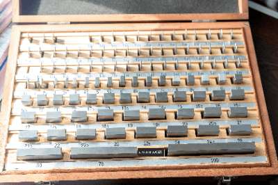
  • Block Gage: A “length” standard used to check the accuracy of measuring instruments.
  • Skimmer Gauge: Gauges used to measure the dimensions of the gap between two surfaces.
  • Welding Gauges: Gauges capable of making a wide variety of welding-related measurements.
  • Angle Gauges: Gauges used for angle inspection.
  • Pitch Gauges: Gauges used to check the pitch of screws.
  • Filler Gauges: Gauges used to measure the dimensions of narrow gaps.
  • Taper Gauges: Gauges used to measure gaps and hole diameters.
  • Center Gauges: Gauges used to check the angles of turning tool cutting edges when threading on a lathe.
  • Radius Gauges: Gauges used to inspect the radius (curved part) of a product.
  • C-Face Measuring Gauge: Gauge used to measure the size of the C-face after C-chamfering.
  • Pin Gauges: Gauges used to measure the diameter of holes.

Other Information on Measuring Gauges

Precautions for Handling Measuring Gauges

Materials, not just measuring gauges, will change dimensions depending on temperature. When handling measuring gauges, make sure they are not extremely heated or cooled. The same applies not only to measuring gauges but also to inspection objects.

In addition, in inspections that are used repeatedly, there is a possibility that wear may occur on the parts that rub against each other over a long period. Measurement gauges, like measuring instruments, should be calibrated periodically to check for dimensional accuracy.

カテゴリー
category_usa

Piezoelectric Actuators

What Is a Piezoelectric Actuators?

A piezoelectric actuator is a type of actuator that converts input energy, or energy output by a computer, into physical motion to form a machine or electrical circuit.

Piezoelectric actuators utilize a piezoelectric element called a piezo to convert electrical energy into physical mechanical energy.

Since piezoelectric actuators utilize the deformation of piezoelectric ceramics, they do not generate electromagnetic noise, have extremely high precision, and have a fast response time compared to other actuators.

Since they do not require a coil to drive the actuator, they can be made compact, and their low power consumption makes them ideal for use in precision equipment such as digital cameras and mobile terminals, where miniaturization is a requirement.

Piezoelectric Actuator Applications

Piezoelectric actuators are used in a wide range of applications, from industrial products to familiar electrical appliances and precision instruments, taking advantage of their compact size, high response speed, and low power consumption.

The fields in which piezoelectric actuators are used are diverse and include the medical, precision instrument, and industrial fields.

Specific products include precision equipment such as single-lens reflex cameras, storage media such as hard disk drives, and inkjet printers, as well as medical equipment and industrial products.

Principles of Piezoelectric Actuators

Piezoelectric material is a substance with a raw piezoelectric effect and reverses voltage effect. Piezoelectric actuators utilize the reverse piezoelectric effect, a characteristic of piezoelectric material, in which force or strain is generated by applying an electric field to the crystal.

The piezoelectric ceramics used in piezoelectric actuators are designed to obtain high displacement from a small drive voltage due to this inverse piezoelectric effect, and by reducing the thickness of the ceramics, the voltage of the piezoelectric actuator can be reduced.

カテゴリー
category_usa

Metal Base Substrates

What Is a Metal Base Substrate?

A metal base substrate is a type of printed circuit board that includes a metal base. This feature has become increasingly important for LED lighting, which requires efficient heat dissipation. As a result, the demand for metal base substrates, such as those made from aluminum and copper, has risen. Unlike standard printed circuit boards, metal base substrates effectively dissipate heat, preventing high temperatures that could shorten the lifespan of components.

Heat dissipation technology is crucial in power electronics as well. Silicon carbide (SiC) substrates, gallium nitride (GaN) substrates, and amplifier substrates all benefit from the use of metal base substrates.

Uses of Metal Base Substrates

Metal base substrates serve various purposes, including substrates for LED lighting, protecting electronic components from heat damage, cooling semiconductor devices in power applications, and functioning in high-temperature environments.

Beyond LED applications, metal base substrates help manage the heat generated by semiconductor elements in power applications, preventing heat damage in hybrid IC automotive electronics, high-density mounting packages, solar power generation systems, and household appliances.

Principle of Metal Base Substrates

The typical structure of a metal base substrate includes an insulating layer atop a metal plate (such as aluminum, copper, or stainless steel), covered by a layer of copper foil. Aluminum and copper, known for their superior heat conduction compared to resins and ceramics, are commonly used metals that enable efficient heat dissipation from LEDs and other devices.

The insulation layer’s thickness is a critical factor in heat dissipation efficiency. A thinner layer enhances heat dissipation but may reduce voltage resistance. The filler content within the insulation layer also influences heat dissipation capacity.

Compared to standard non-metallic FR-4 substrates, which have a thermal conductivity of about 0.38 W/m-K, metal base substrates boast thermal conductivities ranging from 1.1 to 2.5 W/m-K, facilitating faster heat transfer and improved dissipation characteristics.

Types of Metal Base Substrates

There are primarily two types of metal base substrates:

1. Aluminum Substrates

Aluminum substrates, favored for their lightweight and effective heat dissipation, are predominantly used in LED lighting. These substrates consist of copper foil, an insulating layer, and an aluminum base.

There are two variants of aluminum substrates: double-sided aluminum base substrates, designed for single-sided mounting, and double-sided aluminum core substrates, which include an insulating layer and copper foil on both sides of the aluminum base.

2. Copper Substrates

Copper substrates, offering approximately 1.7 times the heat dissipation capacity of aluminum, are ideal for high-heat components. These substrates are heavier and more expensive than their aluminum counterparts, but their superior heat dissipation makes them valuable for specific applications.

Other Information on Metal Base Substrates

Advantages of Metal Base Substrate

1. Superior Heat Dissipation
Metal base substrates excel in heat dissipation compared to traditional FR-4 and CEM-3 substrates, thanks to their high thermal conductivity metal bases.

2. Enhanced Dimensional Stability
With a lower coefficient of thermal expansion (CTE) than conventional substrates, metal substrates offer improved stability under temperature variations.

3. Reduced Strain Transmission
The excellent heat dissipation of metal base substrates leads to lower temperature rises and, consequently, minimized distortion in signal transmission.

Metal base substrates are utilized in various applications, including power converters, lighting, photovoltaics, backlighting, automotive LED systems, and household appliances, due to their unique benefits.

カテゴリー
category_usa

Optical Connectors

What Is an Optical Connector?

Optical Connectors

An optical connector is designed for connecting fiber-optic lines, facilitating the complete connection of optical fiber cables for efficient optical signal transmission. These connectors allow for easy and reliable linkage of optical lines, simplifying installation and maintenance. Precision engineering ensures minimal optical loss, enhancing signal transmission and extending reach.

However, due to their precision, the contact area with the optical fiber must be clean to maintain signal quality and efficiency. Handling in clean environments and using protective caps is crucial.

Uses of Optical Connectors

Optical connectors are widely used across various industries:

  • Telecommunications: In constructing fiber-optic networks for long-distance communication and high-speed data transmission.
  • Data Centers: Connecting servers and storage systems for high bandwidth and signal quality.
  • Other Applications: Including television broadcasting, medical and industrial equipment, and in the aerospace and defense sectors, where high-speed and stable data transmission are crucial.

Principle of Optical Connectors

An optical connector typically comprises a housing and a ferrule holding the fiber end. It operates on the principle of direct end-to-end butting, requiring high-precision alignment to minimize connection loss. Connectors are typically mated using an optical adapter with a split sleeve for alignment. The connector ends are often PC-polished (spherical polishing) to avoid air layer formation and achieve minimal loss connections.

Types of Optical Connectors

Common types of optical connectors include:

  • SC (Subscriber Connector): Features a cylindrical ferrule with a push-pull latching mechanism, commonly used for single-mode fiber optic cables.
  • LC (Luciferous Connector): Small form factor connectors, suitable for high-density cabling environments and used for both single-mode and multimode fibers.
  • ST (Straight Tube): Utilizes a bayonet coupling mechanism, ideal for multimode fibers, often used in network equipment and data communication applications.
  • FC (Fiber Connector): Features a threaded coupling mechanism, offering durability and high signal quality, typically used in industrial and defense applications for single-mode fibers.
カテゴリー
category_usa

Photomultiplier Tubes

What Is a Photomultiplier Tube?

A Photomultiplier Tube (PMT) is one of the most sensitive optical sensors capable of converting light (photons) into electricity.

It consists of a glass tube in a vacuum with an incident window, a photocathode, a dynode, and other components. The principle is based on the external photoelectric effect, a phenomenon in which electrons are emitted from the surface of a metal when light is irradiated on it in a vacuum.

Since even a single photon can be converted into a large electrical signal at high speed (10-9 seconds), photomultiplier tubes are used in electron microscopes, environmental analysis equipment, medical equipment, spectrophotometers, and spectral analysis equipment as photodetectors.

Applications of Photomultiplier Tubes

Photomultiplier Tubes are used as secondary electron detectors in electron microscopes and in photoanalytical instruments such as UV-visible spectrophotometers and emission spectrometers. They are also used in dust counters to measure particles in the air, in laser radar (LiDAR) to detect light scattered by suspended particles in the air, and in medical devices such as positron emission tomography (PET) and computed tomography (CT) used for cancer screening.

LiDAR provides a means of detecting the position and movement of objects around a vehicle and is also expected to be a key technology for fully automated driving. The Super-Kamiokande, the world’s most advanced facility for neutrino research, uses 13,000 20-inch diameter Photomultiplier Tubes to capture the Cherenkov light (light produced when electrons exceed the speed of light in water) generated in a 50,000 ton water tank.

Photomultiplier Tubes are extremely sensitive and are capable of converting faint light into a sufficient amount of electrical signals. On the other hand, they also have disadvantages, such as requiring high voltage for use and being prone to picking up noise caused by thermal electrons. Therefore, the power supply for Photomultiplier Tubes must have extremely low noise and high stability.

Photomultiplier Tube Principle

Figure 1. Basic structure of photomultiplier tubes

Figure 1. Basic structure of photomultiplier tubes

Photomultiplier Tubes are optical sensors that can detect light from a single photon and convert it into an electrical signal. Figure 1 shows the overall structure of a Photomultiplier Tube.

The glass tube in a vacuum state contains a window through which light enters, a photocathode that converts photons into electrons through the external photoelectric effect (the effect of electrons being emitted into a vacuum), a focusing electrode that collects the photoelectrons, a dynode with about 10 stages that multiplies secondary electrons, and an anode that generates an electronic signal. A DC voltage of about 1,000 V is applied to the entire area from the photocathode to the anode.

1. Window Material

Borosilicate glass, quartz glass, UV-transmitting glass, MgF2 crystal, etc. are used as window materials, depending on the wavelength region of the light, mainly on the short wavelength side.

2. Photocathode

Figure 2. Photocathode and external photoelectric effect (Image)

Figure 2. Photocathode and external photoelectric effect (Image)

The photocathode forms a quantum efficient (photoelectron generation efficiency) active layer on the surface in contact with the high vacuum. In the visible region, bialkali metal photocathodes, multi-alkali metal photocathodes of three or more types with sensitivity up to the infrared region, alkali halide photocathodes for UV detection, and photocathodes using III-V compound semiconductors with high sensitivity in the UV to near infrared region have been developed.

3. Die Node

Figure 3. Structure and function of dynode (image)

Figure 3. Structure and function of dynode (image)

Photoelectrons are accelerated by a focusing electrode and collected in a dynode. The dynode forms an active layer that increases the secondary electron emission ratio on a substrate metal such as nickel or stainless steel. Alkali metal-antimony (e.g., SbCs), beryllium oxide, and magnesium oxide are typically deposited on the layers.

When electrons strike the dynode, a large number of secondary electrons are emitted. The emitted secondary electrons collide with the next dynode, where more secondary electrons are emitted. This process is repeated until the number of electrons increases more than one million times, and is detected as a sufficient amount of electrical signal.

Other Information on Photomultiplier Tubes

Structure of Secondary Electron Multiplier

Various structures have been devised for the secondary electron multiplier, such as circular cage type, line focus type, box-and-grid type, fine mesh type, and metal channel type, depending on the arrangement and shape of the dynodes and other components.

For each structure, the optimum electrode design is made by electron orbital analysis. Electrons travel in a high vacuum, enabling fast time characteristic acquisition. The high sensitivity and fast response characteristics that count light as a grain are the reasons why PMTs are used at the forefront of the industry.

カテゴリー
category_usa

High Voltage Resistors

What Is a High Voltage Resistor?

A resistor is an electronic component that acts as a resistance in a circuit and can suppress the flow of electricity. High-voltage resistors are highly accurate resistors that can handle extremely high voltages on the order of kilovolts.

There are a variety of products available for various applications, including resistors that can handle resistance values of up to 100 omega.

They can handle high resistance values and narrow deviations, which can improve reliability and suppress circuit signal variations.

Applications for High Voltage Resistors

Resistors regulate the amount of electricity flowing through a circuit in the form of suppression or help the circuit operate properly. High-voltage resistors are suitable for equipment and applications with high-voltage circuits because they are resistors that can handle high voltages.

Major equipment and applications include high-voltage power supplies, X-ray power supplies, and various high-voltage devices such as printers, copiers, automobiles, air conditioners, lighting, electrostatic discharge, lasers, and power supplies for plasma displays.

Principles of High Voltage Resistors

Resistors are electronic components that can suppress the flow of electricity, but by using conductors with high resistivity as materials among conductors.

High-voltage resistors are specialized for high voltage among resistors, so the parts used can handle high voltage by maintaining high insulation properties.

Based on a substrate and insulator, the resistor consists of a resistive element, a protective coating to protect the element, an external electrode, and an internal electrode connected to the element.

Alumina insulators are mainly used for the insulators.
Each part of the resistor has a structure that can withstand high voltages, making the resistor as a whole capable of withstanding high voltages.
Since the terminal part is the connection point of the resistor and receives voltage and current, a structure and material that does not affect the characteristics of the resistive element are used.

In addition, there are patterns of resistive elements, forming shapes that can withstand high voltages such as solid, meander, and serpentine.

カテゴリー
category_usa

Proportional Counters

What Is a Proportional Counter?

A proportional counter tube is a type of radiation detector. It detects radiation by measuring the number of electrons (electric current), utilizing the fact that when energetic particles pass through a gas, the gas molecules become ionized, producing electrons.

Ionization chambers and GM (Geiger-Müller) counters are radiation detectors based on similar principles, but they differ in the magnitude of the voltage applied to measure the current. Ionization chambers operate at a lower voltage range than proportional counters, while GM counters operate at a higher voltage range than proportional counters.

Applications of Proportional Counters

Proportional counters detect radiation types such as X-rays, α-rays, β-rays, γ-rays, and neutrons, and measure radiation counts and energy. Due to their simple structure and relatively straightforward manufacturing process, they are often employed as detectors in academic research and other fields.

Typically, they are used to measure radiation dose in the air, particularly for neutron detection and β-ray contamination detection. Proportional counter tubes for X-rays are also occasionally integrated as detectors in X-ray fluorescence film thickness meters. These meters are used for non-contact measurements of plating thickness, among other applications, owing to their large incident window and higher efficiency compared to semiconductor detectors.

Principles of Proportional Counters

Proportional counter tubes are typically cylindrical aluminum vessels filled with a mixture of inert gases such as argon, helium, neon, methane, and butane. They operate by applying a high voltage to wires stretched inside the tube. The cylindrical vessel features an incident window through which radiation enters the tube.

When incident radiation passes through the gas, the gas along its path becomes ionized, producing electrons and cations. The electrons produced are referred to as primary electrons. These primary electrons get accelerated by the electric field within the tube and further ionize the gas, leading to a phenomenon known as “gas amplification,” in which the number of electrons increases significantly. The amplified electrons flow into the wire inside the tube and are detected as an electrical pulse.

Since the number of amplified electrons is proportional to the energy of the incident radiation, this detector is called a proportional counter tube. The amplification rate of electrons depends on the type of gas and the applied voltage. However, if the gas and voltage are known, the energy of the incident radiation can be measured.

An ionization chamber operates on a similar principle to the proportional counter but operates at a lower voltage and therefore does not amplify the gas. Consequently, proportional counters have the advantage of higher sensitivity compared to ionization chambers. However, proportional counters may not measure the number of primary electrons as accurately as an ionization chamber, and their energy resolution may be inferior.

カテゴリー
category_usa

Chemical Resistant Gloves

What Is a Chemical-Resistant Glove?

A chemical-resistant glove is designed to offer high-level protection and resistance against chemicals, including acids and alkalis. Solvent-resistant gloves, a subset of chemical-resistant gloves, are specifically designed to shield hands from chemicals such as acids and alkalis.

These gloves provide protection against a wide range of chemicals, including ketones, salts, detergents, and alcohols. They come in two main types: disposable and reusable.

Gloves are available in various thicknesses, with thicker gloves offering greater resistance but potentially making fine-detail work more challenging. Material choice affects durability, abrasion resistance, and chemical resistance, while thickness varies. Therefore, the appropriate type should be selected based on the intended use and specific tasks.

Applications of Chemical-Resistant Gloves

Chemical-resistant gloves find applications across diverse industries, including chemicals, electronics, aerospace, automotive, life sciences, machinery, equipment, metal fabrication, recycling, waste disposal, and the manufacturing of transistors and semiconductors. Specific use cases include:

  • Handling aerospace equipment and components
  • Working with painting tools, including spray guns and robots
  • Managing unexpected chemical leaks and spills
  • Cleaning and maintaining equipment
  • Conducting fitting, dismantling, and assembly operations
  • Processing and producing petrochemical products
  • Performing sampling, experiments, and tests
  • Engaging in shipping operations
  • Handling chemicals in applications such as glass etching, metal plating, dyeing, and chemical plants

Principles of Chemical-Resistant Gloves

The primary materials used in chemical-resistant gloves include natural rubber, nitrile rubber, chlorosulfonated polyethylene, and polyurethane.

Gloves made from these materials undergo permeation resistance tests against various acids and alkalis, such as ammonia, sulfuric acid, nitric acid, hydrochloric acid, and phosphoric acid. Additionally, they undergo swelling rate tests with organic solvents and oils, including ketones, ethers, chlorinated solvents, alcohols, and fats and oils, to assess their performance.

The results of the permeation test are typically evaluated in three levels, while the swelling rate test is evaluated in four levels to indicate the product’s performance.

Features of Chemical-Resistant Gloves by Material

1. Natural Rubber

Natural rubber gloves are resistant to oil and solvents, making them ideal for precision work.

2. Nitrile Rubber

Nitrile rubber gloves conform closely to the hand, allowing for detailed tasks. They have low tension, reducing hand fatigue even during extended use. Nitrile gloves, especially those with excellent static control, dust resistance, and ion control, are suitable for tasks in the electronics and semiconductor industries, as well as chemical processing.

Nitrile is also used in combination with natural rubber for enhanced chemical resistance, making these gloves highly resistant to chemicals such as fuel oil, lubricants, and acids. Some variants feature a diamond surface treatment to prevent slipping. They are commonly used in petrochemical, machinery assembly, aerospace, and chemical industries, as well as for industrial cleaning, heavy equipment assembly, and handling hazardous chemicals.

3. Chlorosulfonated Polyethylene

Chlorosulfonated polyethylene gloves exhibit excellent resistance to aging, ozone, weather, chemicals, abrasion, and acids/alkalis. However, they may have limited resistance to organic solvents.

4. Polyurethane

Polyurethane gloves are known for their abrasion resistance, flexibility, and ease of use. They are commonly employed in tasks such as assembling machine parts, gardening, DIY projects, fruit collection and sorting, packaging, and delivery. Some variants come with a cotton lining for added comfort.

カテゴリー
category_usa

Silicone Rubber Sheet

What Is a Silicone Rubber Sheet?

A silicone rubber sheet is a thin sheet of silicone rubber processed into various shapes with different properties.

It finds applications in a wide range of uses, from everyday necessities to industrial products, and offers diverse functionalities. The natural color of silicone sheets is translucent milky white, but they can be dyed, providing a variety of color options. Different manufacturers may refer to it as a “silicone rubber sheet” or simply a “silicone sheet,” but they all refer to the same material.

Uses of Silicone Sheeting

Silicone sheets are highly versatile and serve various purposes in the following applications:

1. Cushioning and protective materials for precision equipment

When silicone sheets are processed to a thickness as thin as 100 μm and achieve a transparency of 95%, similar to that of glass, they can be used as cushioning materials for precision equipment and protective films for LCD screens and touch panels. Their high elasticity and thin film form allow them to conform to and adhere to free-curved surfaces.

2. Piping Protection

Raw silicone rubber, the material used for silicone sheets, is resistant to ozone, erosion, and ultraviolet rays, making it suitable as a protective material for indoor and outdoor piping. A caterpillar-type silicone sheet is typically used for piping protection.

3. Everyday Items

Silicone sheets, being chemically stable and physiologically inert, have no adverse effects on the human body. They are used in various kitchen utensils and baby products due to their colorless, odorless, and transparent properties.

4. Non-Slip Surfaces

Non-slip trays attached to the bottoms of PCs and smartphones or used inside automobiles are often made of silicone rubber. These non-slip surfaces have a convex shape. Silicone sheets in circular tube or square frame shapes are also used as gaskets.

Principles of Silicone Sheets

Silicone sheets are made from silicone rubber, an organic silicon compound based on the element Si (silicon), which is the second most abundant element on Earth after oxygen.

Silicone rubber exhibits excellent properties such as high-temperature oil resistance, heat resistance, cold resistance, electrical insulation, weather resistance, and chemical resistance. Its high electrical insulation properties make it suitable for use as a potting material to fill gaps between components on circuit boards and insulate them.

Additionally, silicone rubber’s high heat resistance and low thermal conductivity make it suitable for the handles of cooking utensils. Its exceptional chemical resistance makes it useful as a masking material for plating.

Types of Silicone Sheeting

Various types of silicone sheets are available for different applications, and it is crucial to select the appropriate type:

1. Adhesive Type

Some silicone sheets are adhesive and can be easily removed. Special double-sided tape or adhesive is used to attach them. Non-adhesive types require an additional adhesive layer.

2. High Tearing Strength Type

Silicone sheets can be weak against pulling forces, shear relatively easily, and have poor abrasion resistance. Silicone rubber sheets with increased tearing strength have been developed to address this issue, offering improved resistance to tearing and abrasion.

3. Other Types

In addition to the above types, there are:

  • Conductive types achieved by adding conductive materials
  • Heat-dissipating types suitable for cooling high-heat-generating components like CPUs
  • Sponge-like materials with a foamed interior
  • Flame-retardant versions
  • Antimicrobial treatments for food-related applications

Additional Information on Silicone Rubber Sheets

1. Features of Silicone Rubber Sheets

Silicone rubber sheets offer the following key characteristics, making them suitable for a wide range of applications, including industrial products, general-purpose items, home appliances, and daily necessities. They have minimal impact on the human body.

  • Excellent cold and heat resistance, maintaining elasticity within a temperature range of -100°C to 250°C
  • Adjustable shore hardness from less than 10 degrees to more than 90 degrees
  • Good water repellence and oxygen permeability at 25°C
  • Processable in various ways, including full punching, kiss-cutting, slitting, veneering, and laminating, making them suitable for a wide range of products

2. Common Applications of Silicone Rubber

Silicone rubber, the raw material of silicone sheets, is shaped into specified forms and used for sealing purposes in home appliances that require airtightness, such as microwave oven and refrigerator doors.

カテゴリー
category_usa

Degreasing Cleaner

What Is a Degreasing Cleaner?

Degreasing Cleaners

A degreasing Cleaner is a cleaning agent specifically formulated for powerful penetrating and degreasing abilities. They are designed to remove substances like oil and wax, and some varieties also eliminate light rust and prevent corrosion. These cleaners are safe on textiles, leaving no residue and not causing damage.

For enhanced cleaning effects, degreasing cleaners can be used with a sprayer or in conjunction with steam cleaning methods.

Applications of Degreasing Cleaner

Degreasing cleaners have broad applications across various fields:

1. Industrial Fields

Used extensively in industrial environments for cleaning metal parts and machinery. They are effective in removing oil and grease from auto engine parts, machine gears, and bearings.

2. Medical Field

Employed for cleaning and sterilizing medical equipment and instruments in hospitals and dental clinics.

3. General Household

Commonly used in households for cleaning kitchen utensils, effectively removing grease and burnt-on deposits.

Principle of Degreasing Cleaner

Degreasing Cleaners work through their composition of emulsifiers, dispersants, and surfactants:

1. Emulsifiers

Facilitate the mixing of oil or fat with water, dispersing them into tiny particles for emulsification.

2. Dispersants

Disperse contaminants into microscopic particles, detaching them from surfaces for removal.

3. Surfactants

Reduce surface tension between water and oil, enhancing the water’s ability to penetrate and effectively remove stains.

Types of Degreasing Cleaners

Degreasing cleaners vary based on their composition:

1. Hydrocarbon-Based Cleaning Agents

Mainly composed of petroleum-derived solvents like trichloroethylene, these cleaners dissolve oil and fat and are effective for cleaning metal parts. They are efficient but regulated due to environmental concerns.

2. Organic Solvent-Based Cleaning Agents

Comprising organic compounds such as alcohols, ketones, and ethers, these cleaners excel in removing oily stains and are widely used in industrial cleaning.

3. Alkaline Cleaning Agents

Consisting mainly of alkaline substances like sodium hydroxide and potassium hydroxide, these agents are effective but can cause rust and discoloration in metal parts.

Other Information on Degreasing Cleaner

Disposal of Degreasing Cleaner

Proper disposal of degreasing cleaners, whether hydrocarbon-based or alkaline, is essential to prevent environmental harm. Recommendations often include incineration or specialized waste disposal methods.