What Is a Rotary Position/Angle Sensor?
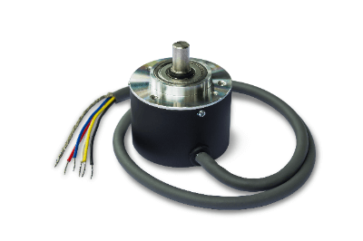
Rotary Position/Angle Sensors are sensors for detecting angular information from the position of an object.
In recent times, there has been a growing need for high-precision position detection due to precision processing, semiconductor manufacturing, automobiles, and robotics. Furthermore, the need to measure precise angles for position detection is also increasing.
Rotary Position/Angle Sensors are generally available in magnetic, optical, inductive, potentiometer, and other types of angle detection methods. It is important to select the most appropriate method according to the application of use.
Recently, gyro sensors, which detect inertial forces such as angular velocity and acceleration in addition to angular position, have been attracting attention in support of automatic driving. The trend is toward the use of gyro-sensors in addition to conventional Rotary Position/Angle Sensors.
Applications of Rotary Position/Angle Sensors
Rotary Position/Angle Sensors are used in precision processing, semiconductor manufacturing, automobiles, and robotics.
1. Automotive
By detecting the crank angle and cam angle with Rotary Position/Angle Sensors, the optimal timing and duration of fuel injection can be calculated. Other applications include electric power steering and electronically controlled suspension.
2. Robots
Angle sensors are used to detect and control the position of robot arms.
Principle of Rotary Position/Angle Sensor
Rotary Position/Angle Sensors are generally classified into four types: magnetic, optical, inductive, and potentiometer.
1. Magnetic Type
This method detects angles by measuring the voltage generated when a magnetic field is applied perpendicularly to a Hall element while a current is flowing through it. This phenomenon is called the Hall effect.
2. Optical Method
This method detects angles by passing light through a disk with a slit-like grating and measuring the number of detected light pulses. This method is called the transmission type. Another method is the reflection type.
In the reflective type, the angle is measured by the light pulses that bounce from the light emitting element to the disc and are received by the light receiving element.
3. Inductive Type
The inductive type consists of a primary coil, a secondary coil, and a cam-shaped core that rotates between the primary and secondary coils.
4. Potentiometer Type
Potentiometers have terminals, and brushes rotate on a resistive element. By measuring the resistance value between the terminals, the angle of rotation of the brush can be measured.
Other Information on Rotary Position/Angle Sensors
1. Advantages of Magnetic Rotary Position/Angle Sensors
Magnetic Rotary Position/Angle Sensors use the Hall effect to convert changes in the magnetic field into a voltage value, which is output as an analog output signal. Unlike potentiometers, magnetic Rotary Position/Angle Sensors may have two output systems, and the two output values are generally different, except for the neutral position.
Having two outputs increases the detected value and the reliability of the Rotary Position/Angle Sensor. Potentiometric angle centers require two Rotary Position/Angle Sensors to provide 360° angle detection, because the structure of the angle center always has a blind spot.
However, a magnetic Rotary Position/Angle Sensor can detect 360° with only one angle sensor, thus reducing the number of components required. Since the magnetic Rotary Position/Angle Sensor is non-contact, it has fewer failure factors and a longer service life than contact-type sensors such as potentiometer-type angle sensors.
However, if a failure should occur, care should be taken with the distance to the sensing element. If the distance adjustment is not considered when reinstalling the sensor, premature failure of the Rotary Position/Angle Sensor will occur in case of contact, and the angle will not be detected correctly if the distance from the sensing body is too far.
2. Analog Output of Rotary Position/Angle Sensor
The voltage value, which is the analog output of Rotary Position/Angle Sensor, is output by the change in electrical resistance. The output method is often voltage, but it can also be current, and the analog output range differs depending on the Rotary Position/Angle Sensor. For voltage, the range is not only 0 to 5V, but also 0 to 10V, so it is important to check the manufacturer’s specifications carefully.
Rotary Position/Angle Sensors require a power circuit and ground (GND) for analog output. Therefore, the Rotary Position/Angle Sensor has three terminals: the power terminal, the ground terminal (GND), and the analog output terminal. If the analog output is abnormal, the cause may be an abnormal wiring or connection in addition to the failure of the Rotary Position/Angle Sensor itself.

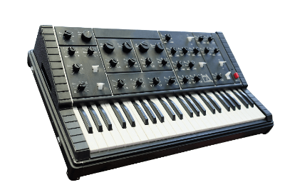 A synthesizer is a device that uses electronic circuitry to generate sound.
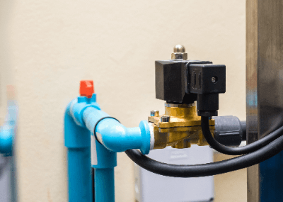 A solenoid valve is a valve that opens and closes by means of an electromagnetic coil.
 Barrel finishing machine is a general term for machines that polishes objects through friction by moving abrasives in a barrel container.