カテゴリー
category_usa

Burets

What Is a Buret?

Burets

A buret is a glassware that can measure the volume of liquid dropped by dropping a small amount of liquid while operating it with a cock.

A removable cock is attached to the bottom of a thin, tubular glass tube with a scale on it, and the amount of liquid dropped is adjusted by turning the cock.

A pipette can also be used to measure the volume of a dropped liquid, but the buret can be used in a vertical position, so the scale can be read more precisely and the amount of liquid can be adjusted finely with the cock. Moreover, since the volume of a drop can be precisely controlled with a cock, the buret is suitable for experiments that require accurate liquid volume measurement, such as neutralization titration.

Uses for burets

Buret is mainly used for neutralization titration. Neutralization titration is a type of volumetric analysis, in which the concentration of a solution of unknown concentration is determined using a standard solution of known concentration and a solution of unknown concentration that reacts in proportion to the concentration of the standard solution.

The judgment of the neutralization reaction, the so-called endpoint, is determined by the color change of the mixed solution after dropping. Although the operation of the cock requires a certain degree of skill, an automatic operation called auto-buret is also available and is used for quality control in the food, pharmaceutical, and chemical industries.

Features of burets

Burets are available in white and brown. As with other glassware, some substances react with light, so the choice should be made according to the type of substance dissolved in the standard solution. For example, silver nitrate is photosensitive and must be used under a light-shielded condition, so a brown buret must be used when using it as a titrant.

Also, as mentioned above, it is important to become familiar with the buret’s cocking operation. If the speed of dropping liquid from the buret is too fast, there is a possibility of adding more standard solution than the endpoint. In addition, it is necessary to grease the cock part for maintenance, and if maintenance is insufficient, liquid may leak, etc.

Furthermore, if the tip is chipped, it is impossible to accurately measure the volume, so it must be handled with care. Experiments have shown that even a scratch on the tip can change the volume per drop. It is also known that the volume of residual liquid in the buret changes the volume of the residual drop, so it is advisable to always use the buret from the top of the scale, which is the zero point.

Since the buret is glassware, repeated heating and cooling deforms it, which impairs the accuracy of its measurement volume. Therefore, heating and drying after washing should be avoided, and the buret should be dried at room temperature. For the same reason, the titrant to be placed in the buret should be a liquid with a constant temperature of about room temperature. The temperature of the titrant should be considered not only because it causes expansion and deformation of the buret, but also because the volume of the titrant is temperature-dependent. For this reason, the titrant should be at a constant temperature for accurate volume measurement.

Why co-wash a buret?

Co-washing is the process of washing a buret, a whole pipette, or another side vessel instrument (an instrument used to measure the volume of a liquid) with the solution to be weighed (the solution to be placed inside).

To avoid volume changes due to deformation of the instrument, side vessel instruments are usually not heated and dried in a dryer. After washing with tap water, they are rinsed with distilled water and washed with the solution to be weighed immediately before use.

The reason for co-washing is that the concentration of the sample solution decreases when the inner surface of the instrument is wet with water. On the other hand, if the sample solution itself is wet, the concentration does not change when the solution is added.

Since a buret is used to put in a solution of unknown concentration during titration, if the concentration of the solution changes inside the buret, it will be impossible to obtain an accurate concentration.

Also, if you co-wash the apparatus once used again, you can continue to use it without letting it dry out.

First, fill the buret about 1/5 of the way with a solution and wash the inner walls while turning the buret on its side. Next, turn the cock to let the solution out of the tip, wash the inner wall below the cock, and discard the remaining solution from the top. This process is repeated several times. 

How to use the buret

Fix the buret vertically to the buret stand and make sure the live plug is closed.

Using a funnel, pour the solution from the top of the glass tube. To prevent the solution from overflowing from the top of the funnel, leave a gap between the funnel and the top of the buret to allow air to escape. Also, to prevent the solution from getting into the eyes, pour the solution below eye level. After pouring the solution, remove the funnel.

Open the stopper with a beaker or other container underneath, and pour out the solution vigorously to completely expel air bubbles from the area below the stopper. If there are air bubbles above the stopper, remove them as well.

After the air has been expelled, read the scale and record the reading. The bottom (lower end) of the “meniscus” should be read, with the buret perpendicular to the line of sight. The meniscus is the curved surface of the liquid in a narrow tube due to surface tension, or a dent if the liquid wets the tube wall. The scale is read by eye to the nearest 1/10 of the smallest scale.

Turn the stopper to start dripping. Hold the buret with one hand and pull it toward the main body of the buret to prevent the stopper from falling out.

When titration is completed, read the scale to determine the volume to be titrated.
カテゴリー
category_usa

Cable Glands

What Is a Cable Gland?

Cable Glands

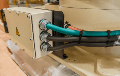
Cable glands, essential in electrical systems, are devices used to insert and securely fasten electrical cables into control panels and operation panel enclosures and equipment.

The main functions of a cable gland are as follows:

External environmental protection: Prevents dust, dirt, and moisture from entering through openings in enclosures such as control panels.
Retention: Securely holds cables in place and prevents them from loosening under external mechanical tension or vibration.
Sealing: Prevents dust and water from entering the cable from the outside.

JIS F8801 “Marine Wire Penetration Hardware” is the standard for cable glands.

Uses of Cable Glands

Cable glands, vital for ensuring safe and secure cable connections, are used to penetrate enclosure walls by attaching to cable intakes in devices like control panels. They are crucial in both indoor and outdoor wiring setups of electrical and control equipment.

These glands protect against dust and water ingress in control and operation panel enclosures, mitigate disconnection risks from vibrations or pulling, and ensure secure cable fastening and management.

Available in various materials like stainless steel and polyamide resin (PA), selecting a cable gland suitable for specific environments—such as outdoor, oily, or high-temperature conditions—is critical for optimal performance.

Alongside cable glands, cable clamps are also used for introducing cables into enclosures. While cable glands are typically employed for single cable entries, a ground clamp is more suited for multiple cable installations.


カテゴリー
category_usa

High Voltage Transformers

What Is a High Voltage Transformer?

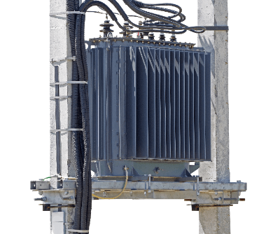
High Voltage TransformersA high voltage transformer is a transformer that inputs high voltage as a primary voltage and outputs a stepped-down or stepped-up secondary voltage.
A transformer is a device that converts the voltage of an input current to another voltage for output. Converting to a lower voltage than the input voltage is called step-down, and conversely, converting to a higher voltage is called step-up. There are three types of power supply voltage standards: low voltage, high voltage, and special high voltage.

Uses of High Voltage Transformers

High voltage transformers are generally used to supply power to large facilities with high power consumption, such as factories, hospitals, and commercial facilities.

Electricity generated at power plants is very high voltage, tens of thousands of volts. This power cannot be used if it is transmitted directly to users. However, from the standpoint of transmission efficiency, the power is transmitted at high voltage and low current in the vicinity of the supplier, and then stepped down to a voltage that can be used by a high-voltage transformer.

High voltage transformers are generally built into high voltage receiving facilities called cubicles and placed on rooftops.

Principle of High Voltage Transformers

A transformer consists of two coils. The two coils are electrically separated but magnetically connected by an iron core.

The coil on the input side is the primary coil and the output side is the secondary coil. When a current flows through the primary coil, a magnetic flux is generated based on Ampere’s law. This magnetic flux is transmitted through the iron core to the secondary coil, and based on Faraday’s law of electromagnetic induction, a voltage corresponding to the number of turns of the coil is generated. Thus, by using the coil and iron core, it is possible to convert the voltage between the input and output power sources.

Other Information on High Voltage Transformers

1. Cooling System of High Voltage Transformer

Since heat is generated inside the transformer due to power loss, a cooling system is introduced. There are two types of cooling methods: the “oil-filled method” in which the windings are cooled with insulating oil, and the “molded method” in which no oil is used.

Since high voltage transformers are used in facilities where strict disaster prevention measures are required, the “molded type” is often adopted because of its low fire risk. In the case of oil-filled transformers, Class 3 petroleum is used for the insulating oil. Note that as the capacity of the high voltage transformer increases and the amount of oil exceeds 400 L, the oil by itself is considered a hazardous material.

Also, as the capacity increases, it becomes more difficult to use self-cooling transformers, so the forced circulation type is used.

2. Price of High Voltage Transformers

High voltage transformers are relatively inexpensive among industrial equipment because of their simple mechanism. For a transformer with a typical temporary voltage of 6,600V/3,300V and a secondary voltage of 400V/200V/105V, catalog products are available from various heavy electric appliance companies.

Catalog products are considered having an upper limit of around 2,000 kVA, and anything above that is made-to-order. The average price of an oil-filled, self-cooling transformer is several hundred thousand yen for a transformer of several tens of kVA, and several million to 20 million yen for a transformer of 2,000 kVA (as of 2021). Molded systems are more expensive.

The above prices are for general step-down transformers, but those with special specifications are made-to-order, so consultation with heavy electric machinery companies is required for pricing. 

3.High Voltage Transformer Capacity

The capacity of a high voltage transformer is determined by the allowable current value of the windings and the capacity of the magnetic iron core. If a current exceeding the allowable value flows through the windings, the transformer is protected by an overcurrent relay to prevent burnout.

The capacity of a three-phase motor, for example, is measured in kilowatts (kW), whereas the capacity of a high voltage Transformer is measured in kilovolts (kVA). Catalog products of single-phase, three-wire High Voltage Transformers have an upper limit around 300 kVA, while three-phase 400 V/200 V transformers have an upper limit of 2,000 kVA.

In the case of a cubicle type, the upper limit for commercial products is around 750 kVA due to the size of the enclosure and cooling capacity. 

4. Power Factor of High Voltage Transformers

It is important to note that the amount of work applied to a high voltage transformer varies depending on the power factor of the load. The further the power factor is from 1, the less work can be applied. By keeping the power factor of the secondary side of the high voltage Transformer at 1, the high voltage transformer can be used to its capacity without waste.

Since industrial machinery has many motors, the power factor often swings in the lagging direction. As a general measure, a power capacitor is connected in parallel with the load to compensate.

High voltage transformers are designed for maximum efficiency at around 60% load. Therefore, it is important to select a capacitor with a generous margin so that the normally used capacity will be around 60%.

カテゴリー
category_usa

Surge Absorbers

What Is a Surge Absorber?

A Surge Absorber is a device that protects equipment from surge voltage.

Surge voltage is a high voltage that rises steeply, and a typical example is the lightning surge voltage caused by a lightning strikes. Surge voltages are generated not only by lightning, but also by switching of high power conductors and static electricity.

Equipment connected to a circuit where surge voltage is generated is at risk of damage due to insulation breakdown. A device that absorbs surge voltage is called a surge absorber.

In other words, it is a device that protects equipment from momentary abnormal voltage.

Usage of Surge Absorbers

There are two types of surge absorbers, one for power circuits and the other for control circuits. Surge absorbers for power circuits are classified into two categories: lightning protection and switching surge voltage absorption.

Surge absorbers for lightning protection are used on utility poles, etc., to release abnormal voltage to the earth in the event of a lightning strike. In this application, they are also called “surge arresters“.

Surge Absorbers for open/close surge voltage absorption are used in high-voltage panels.

Surge Absorbers for control circuits are used in LAN circuits and telephone circuits. The main purpose is to protect office automation equipment and precision control equipment from lightning strikes, etc.

In addition to office automation equipment, surge absorbers are used to protect telephones, fax machines, modems, TV antennas, displays, and car navigation systems.

Principle of Surge Absorber

Surge Absorbers are devices that disconnect surge voltage from the main circuit. There are two main types of surge absorbers: those that absorb surge voltages due to ground faults and those that absorb surge voltages due to resistance.

The ground-fault type absorbs only abnormal voltages by means of semiconductors or discharge tubes. This type is used for equipment that may be subject to lightning strikes. The type that absorbs by resistance absorbs abnormal voltages using coils and resistors. Surge absorbers are mainly used to absorb surge voltages other than those caused by lightning strikes.

Types of Surge Absorbers

There are several types of Surge Absorbers. The principle and characteristics differ depending on the type.

1. ZnO Type Surge Absorber

The ZnO type surge absorber is the most common type of used for lightning surges. Zinc Oxide (ZnO) is a type of semiconductor with low resistance to high voltage.

Grounding a circuit through ZnO allows surge voltages to escape to the earth in the event of an abnormality. It is used in a wide range of circuits from small to large capacitance circuits.

2. CR Type Surge Absorber

A capacitor or resistor is installed in parallel with the circuit to be protected. The capacitor acts to protect the circuit by passing current through the resistor in the event of an abnormally high voltage. They are mainly used in small-capacity circuits and are sometimes called surge killers. 

3. Diode Type Surge Absorber

A diode is installed in parallel with the circuit to be protected, and the rectifying action of the diode absorbs the surge voltage. They can only be used in DC circuits and are used in circuits with relatively small capacitance.

4. Surge Absorber With Discharge Tube

A grounded discharge tube is built into the circuit to release high voltages to the earth. The inside of the tube is filled with inert gas, and the operating voltage is adjusted according to the gap in the tube. While large-capacity discharges are possible, there is a disadvantage of slow operation speed.

In addition to the above, there are surge absorbers that use thyristors for grounding. Surge absorbers act as a device that does not exist in the circuit during normal operation when no surges are present. When a surge enters the circuit, the surge absorber quickly absorbs the surge current and protects the circuit.

In practice, however, surge absorbers inevitably have a delay before they react. The longer the delay time, the more damage is caused to the circuit; surge absorbers using semiconductors such as ZnO type have a feature of short delay time. For this reason, ZnO type surge absorbers are the most common type of surge absorber today.

Today’s precision equipment is becoming more and more vulnerable to surges as it becomes more sophisticated and compact. Thyristors and ZnO elements also have large capacitance, and there is a danger of distorting the waveform of weak electric circuits, so they must be incorporated with consideration.

カテゴリー
category_usa

PEEK Tubing

What Is PEEK Tubing?

PEEK Tubing

PEEK tubing, made from poly ether ether ketone, is a high-performance engineering plastic known for its exceptional mechanical strength, pressure resistance, heat resistance, and chemical stability. It is widely used in the medical field, chemical analysis, and various industrial applications due to its robust properties.

Uses of PEEK Tubing

PEEK tubing finds applications in:

  • Medical tubing for catheters and chemical delivery systems.
  • High-performance liquid chromatography (HPLC) for separating chemical compounds.
  • Protection tubes in semiconductor manufacturing and for optical fibers.
  • Alternative to metal and glass tubes in laboratories and industrial settings.

Principle of PEEK Tubing

PEEK tubing is fabricated from poly ether ether ketone, a super-engineered plastic with a linear polymer structure, ensuring high tensile strength and resistance to extreme conditions such as high temperatures, pressures, and corrosive chemicals. Despite its high cost and difficulty in machining due to its strength, PEEK’s unique properties make it indispensable for critical applications.

Characteristics of PEEK Tubing

Key features include:

  • High mechanical strength, suitable for high-pressure applications.
  • Exceptional heat and chemical resistance, maintaining stability in acidic and alkaline environments.
  • Conformity to safety and hygiene standards, including UL standards for steam resistance and flame retardance, as well as food safety regulations.

Types of PEEK Tubing

Available in various inner diameters, lengths, and colors to match specific application requirements, from ultra-thin tubes for precision work to thicker tubes for robust needs. Colored tubing aids in routing identification in complex setups.

Other Information on PEEK Tubing

1. How PEEK Tubing Is Manufactured

Manufactured primarily through extrusion, allowing for a wide range of sizes and shapes, including thin-walled tubes and custom configurations for specific applications.

2. The Future of PEEK Tubing

Continual development of PEEK tubing includes innovations like silicone rubber coatings for special conditions, enhancing its utility and performance in demanding environments.

カテゴリー
category_usa

PFA Tubing

What Is PFA Tubing?

PFA tubing, made from a fluoroplastic known as PFA, is a versatile and durable tubing option used in various industrial and medical applications. This translucent tubing is heat resistant from -40°C to 260°C and boasts a high non-adhesive quality, making it ideal for handling viscous liquids without residue buildup. Its composition, free from plasticizers and additives, ensures that no excess components leach into liquids passing through it.

Uses for PFA Tubing

PFA tubing’s resistance to strong acids, alkalis, and corrosive agents makes it ideal for use in liquid crystal manufacturing, chemical plants, semiconductor manufacturing equipment, analyzers for liquids and gases, and acid-alkali cleaning in plating factories. Its suitability for transporting chemicals, fuel, oil, and steam also extends to laboratory settings, where its reliability and convenience are highly valued.

Additionally, PFA tubing is employed in the automotive and aerospace industries for wiring sheathing, offering protection against harsh environmental conditions.

Principle of PFA Tubing

PFA tubing is crafted from a copolymer of tetrafluoroethylene and (Perfluorohexyl) ethylene, granting it exceptional heat and chemical resistance. Its lower viscosity when melted compared to PTFE allows for easier processing and flexibility, enabling it to be shaped into tubes. PFA tubing stands out for its resistance to extreme conditions, excellent electrical insulation, and weather resistance, attributed to its fluorocarbon resin composition.

The extrusion process involves heating and melting PFA pellets, shaping them into tubes, and then cooling them in water. The selection of corrosion-resistant metals for production equipment is crucial due to the generation of minute amounts of decomposition products during melting.

Available in various grades, PFA tubing can be tailored to specific applications, ensuring optimal performance in diverse environments.

カテゴリー
category_usa

Crawler Cranes

What Is a Crawler Crane?

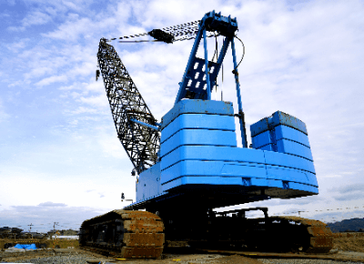
Crawler CranesA Crawler Crane is a crane that can travel on an infinite track called a crawler.

It can move to the lifting location by itself and perform the work. Compared to wheel cranes that travel on tires, crawler cranes have a larger footprint and lower ground contact pressure, allowing them to be used on uneven ground or soft ground.

It also has the advantage of having the same lifting capacity in all directions around its circumference. On the other hand, since these cranes cannot be driven on public roads, they must be loaded on trailers for transportation, and cranes over a certain size must be disassembled for transportation.

Uses of Crawler Cranes

Crawler Cranes are often used in industries and workplaces that require lifting large, heavy materials over a wide work area, such as port construction, plant construction, wind power plant construction, etc.

Smaller cranes (less than 5 tons) are called mini Crawler Cranes and are often used for narrow road construction, stone and garden construction, etc. They are often used for narrow road construction, stone and garden work, etc.

The footprint of a Crawler Crane is large, and it has a large lifting capacity among mobile cranes. Lifting capacities range from as small as 0.5 tons to as large as 500 tons and up to the 3,000-ton class. Furthermore, the crane itself is equipped with a prime mover (mainly a diesel engine), enabling it to be self-propelled at the work site.

Principle of Crawler Cranes

A Crawler Crane consists of a traveling section, a crane body, and a tower.

1. Traveling Section

The traveling section consists of a grounding member called a crawler shoe, a driving unit such as a traveling motor, and driving rollers and sliding rollers. A traveling motor is installed in each of the left and right crawler shoes.

The traveling motors are often of the hydraulic type because they require high output power, and can move forward and backward by switching the oil flow path. The hydraulic pump is located in the crane body at the top and feeds oil to the traveling section at the bottom through a rotating joint called a swivel joint or rotary joint. The traveling section supports and moves the weight of the lifting members and the upper crane body. 

2. Crane Body

The main body of the crane includes the base of the tower, operating equipment, control room, engine, hydraulic pumps, and slewing gear.

The crane body and the tower section are supported by large bearings on the traveling section and can swivel freely. The slewing gear on the crane body side is driven by a slewing motor. The inner gear of the ring body is fixed to the traveling section side. Rotation of the slewing gear on the main body side causes the crane body to slew, since the gear on the traveling section side that is engaged is fixed.

The crane uses a wire rope to lift the material, and the wire rope winding drum, winding motor, reduction gear, safety devices, etc. are equipped on the crane body. 

3. Tower Section

The tower section consists of various parts, including the boom, which is the arm of the crane, and the hooks and wire ropes used to hoist the components.

Fixed-length lattice booms are used on large cranes. Products with telescopic booms that can be extended and retracted using hydraulic cylinders are on the rise.

カテゴリー
category_usa

Graphene

What Is Graphene?

GrapheneGraphene is a sheet-like material composed entirely of carbon atoms.
The carbon atoms bond to each other to form a hexagonal honeycomb structure that spreads out in two dimensions. Since it is not ordered in the height direction, it is only as thick as a single carbon atom. As a result, it is very thin and transparent.

Uses of Graphene

Graphene is used in a wide range of fields due to its transparency and excellent thermoelectric and electrical conductivity.

1. Electronics

Graphene’s extremely thin and transparent properties make it suitable for display applications. Graphene also has the fastest electron transfer rate of any material at room temperature. Therefore, applications in transparent touch panels, conductive films, and solar cells are also expected. Furthermore, its chemical resistance and heat resistance are attracting attention as a substitute for silicon and other materials.

2. Fiber

Graphene itself is difficult to process into fibers, but development of fibers containing graphene is in progress. Fibers containing graphene are expected to be used as novel materials in various industries because they have functions similar to those of graphene. In the clothing industry, in particular, graphene is attracting attention because it fully satisfies the functions required for clothing.

Principle of Graphene

Graphene is conductive because the electrons occupying the 2pz orbitals of the carbon atoms can move freely in the plane. Each carbon atom has four valence electrons. Three of these valence electrons are distributed in sp2 hybrid orbitals (orbitals in the sheet direction), and the remaining one is distributed in the 2pz orbital (orbital perpendicular to the sheet).

Valence electrons occupying the 2pz orbitals are free electrons and can move freely within graphene. This makes graphene an excellent electrical conductor.

Other Information about Graphene

1. How Graphene Is Made

Graphene, the subject of the 2010 Nobel Prize in Physics, can be made by simply attaching tape to graphite, which is composed of layers of carbon atoms, and then removing the tape to collect the graphene attached to the tape surface.

Unlike the former physical method of making graphene, the chemical vapor deposition (CVD) method is a way to make it chemically. Graphene can be produced by a chemical reaction of methane, hydrogen, and argon gases on a heated substrate.

カテゴリー
category_usa

Grippers

What Is a Gripper?

Grippers

A gripper is a mechanism that grasps (grabs and holds) an object.

The shape of a gripper varies depending on the application, but the most commonly used gripper is a two-finger parallel gripper in which two parallel fingers move in a linear motion to clamp an object. This gripper is used as a device (end-effector) that functions at the end of a robot arm or linear motion mechanism.

By utilizing a gripper, it is possible to grasp, transport, and place objects of various shapes, thereby automating and increasing the efficiency of tasks that were previously performed manually.

Uses of Grippers

Various types of grippers exist in terms of the number of fingers, shape, and type of power source, but this section describes the most common two-finger parallel gripper.

There are two main types of grippers commonly used on product production lines: those with two fingers that open and close pneumatically and those with two fingers that open and close electrically. Variations in gripping force, size, and finger shape are also provided for each product.

When used in a linear motion mechanism such as a cylinder or at the end of a robot arm, the gripper is selected according to the specifications of the moving equipment to be fixed, such as matching the power source and setting the weight of the gripper to less than the payload capacity.

Gripper specifications also vary depending on the shape of the object to be gripped, and when gripping curved surfaces or fragile objects, flexible materials are used on the finger surfaces.

Principles of Grippers

Grippers can be broadly classified according to the power source: pneumatic grippers and electric grippers.

Pneumatic grippers are divided into two closed spaces inside, and when high-pressure air flows into one space, the gripper closes, and when the other space is pressurized, the gripper opens. The high-pressure air piping in the factory is connected to these two spaces, and the opening and closing operation of the gripper is controlled by switching the connection with a solenoid valve or the like.

Pneumatic grippers can be controlled by simply switching open/close valves in the air piping, so they can be operated with simple control using only relays, and their relatively simple mechanism has the advantage of being inexpensive.

Electric grippers incorporate a motor and a feed screw inside, and the opening and closing motion of the gripper is controlled by controlling the direction and speed of rotation of the motor.

Since it is operated by a motor, it is possible to construct complex controls, but a controller such as a PLC is required. Another advantage is that multiple types of objects can be grasped, and the opening and closing widths can be changed at will.

In addition, grippers with three or more fingers may be used when more complex shapes are to be grasped or when human motions are to be learned.

カテゴリー
category_usa

Autosampler

What Is an Autosampler?

Automatic Samplers

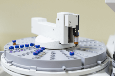
An Autosampler is an automated sample preparation device.

When an analyzer is used to perform some type of analysis, it is common for the sample to be introduced manually. By using an Autosampler, the sample can be automatically supplied and analyzed.

Basically, they are used in combination with analyzers such as elemental analyzers and chromatography. Various types of Autosamplers have been developed to match the introduction system of analyzers, such as for solid samples and liquid samples.

Uses of Autosamplers

Autosamplers are used in a variety of industrial fields. Typical applications include chromatography, environmental analysis, and the pharmaceutical and food industries.

They are used to automatically inject samples in analyses such as liquid chromatography (LC) and gas chromatography (GC). Autosamplers allow for more accurate and faster analysis than manual injection of samples.

In environmental analysis, it is used to measure the concentration of contaminants in water or air. Because of its ability to continuously measure at regular intervals, it is an indispensable instrument in continuous control plants for process systems.

It is also widely used in the food industry and the pharmaceutical field. In the medical field, they are used for testing blood and urine, efficiently processing a large number of samples. In the pharmaceutical field, autosamplers are used to analyze ingredients of raw materials and products, and are valued as a means of high-precision, high-volume analysis.

Principle of Autosampler

Autosamplers are available in a wide variety of types and applications, each with different principles.

When analyzing with an autosampler, the first step is to prepare the sample. The sample to be injected is placed in a sample dish, microplate, or other sample containers in advance, and the injection volume and number of injections are set according to the sample volume and concentration. Many Autosamplers are designed to perform sample preparation automatically.

After sample preparation is complete, the sample in the sample container is set in the Autosampler and automatically fed. Some autosamplers may also have functions to automatically mix the sample and control the temperature.

Once the sample is supplied, the analyzer automatically performs the analysis. The analysis results are processed by the autosampler and may be sent to a PC or data acquisition device.

Types of Autosamplers

There are various types of autosamplers, depending on the type of analyzer and sample used. The following are some of the types of autosamplers:

1. Random Access Type

This type of autosampler can randomly supply various types of samples. It is used to process a large volume of samples and can do so with high efficiency. It is characterized by its high analytical versatility. 

2. Front Access Type

The front-access type is an autosampler in which the sample is manually loaded from the front panel. Since the sample is not automatically supplied, the user must take the time to set and remove the sample. However, the instrument is easy to handle and sample setting is easier than with manual samplers.

Front-access models require manual setting and are used to process small sample volumes. It is suitable for the use of expensive reagents and for the analysis of trace samples. Due to their characteristics, these products are used in the research and development field.

3. Carry-Fill Type

This type of autosampler supplies samples by automatically aspirating samples. It is used in liquid chromatography, for example, when there is a suitable sample in the aspiration section.

In dye analysis and fluorescence spectrum analysis, it is used to achieve accurate sample supply. It is also used in cell culture analysis to automate sample delivery. 

4. Microplates

An autosampler that uses microplates to process multiple samples at once. They are used for analyses that require high throughput rates.