カテゴリー
category_usa

Densimeters

What Is a Densimeter?

Densimeters

Specific gravity refers to the ratio of the mass of a particular substance to the mass of an equivalent volume of a standard substance.

A densimeter, also known as a specific gravity meter, is a device used to measure this specific gravity. While the term specific gravity applies to solids, liquids, and gases, this article focuses on densimeters used for measuring the specific gravity of liquids.

In simple terms, the principle involves measuring the buoyancy force acting on an object. If the specific gravity of water is considered as 1, an object will sink if its specific gravity is greater than 1 and float if it’s less. The most common device that operates based on this principle is the hydrometer.

A hydrometer is a calibrated scale that floats in a liquid, and the specific gravity is determined by reading the scale.

Modern densimeters have evolved to include various types such as load cell-based, vibration-based, differential pressure-based, and radiation-based models. Some of these newer models feature digital displays, simplifying the measurement process compared to traditional hydrometers.

Applications of Specific Gravity Meters

Densimeters find applications in a wide range of fields, including pharmaceuticals, food processing, industry, and scientific research.

Common uses include:

  • Measuring the salinity of seawater
  • Assessing the sugar content of fruits used in juice production
  • Determining the concentration of various chemical solutions in industries like semiconductors, plating, and battery electrolytes
  • Measuring fat content in milk
  • Calculating alcohol content by volume ratio in alcoholic products
  • Assessing impurity levels in petroleum products

Principles of Densimeters

The basic structure of a hydrometer is depicted in Figure 1. It consists of a body that provides buoyancy and a scale placed within it.

The lower part of the body contains an adjustable weight for buoyancy control. When immersed in the liquid to be measured, the buoyancy acting on the scale equals the weight of the liquid displaced by the scale’s volume.

As a result, the scale sinks into the liquid to a degree where its weight is balanced by the buoyancy force. The scale is graduated, and when equilibrium is reached, the reading on the scale corresponds to the liquid’s surface.

While most hydrometers are constructed from glass, plastic hydrometers are also available.

Other Types of Densimeters

Non-Floating Scale Densimeters

Besides hydrometers, other types of densimeters are primarily used in industrial settings. These include load cell-based, vibration-based, differential pressure-based, and radiation-based densimeters.

A load cell densimeter converts force magnitude into an electrical signal to precisely measure the weight of a submerged object in a liquid. It calculates the specific gravity of the test liquid based on the load change.

These densimeters offer higher measurement accuracy compared to conventional hydrometer-type densimeters and are less susceptible to operator skill variations, making them ideal for analytical tasks.

Vibration-based densimeters involve injecting the test liquid into a U-tube, which is then vibrated externally. The U-tube vibrates at a frequency determined by its mass, including the liquid. Consequently, the liquid’s mass within the U-tube can be calculated from this frequency, allowing the density of the sample to be determined.

These densimeters are widely used for quality control, particularly in the food industry, due to their intuitive operation and rapid measurement capabilities.

Differential pressure densimeters utilize pressure differences between two points along a measuring tube, which are proportional to the liquid’s specific gravity.

Radiation-based densimeters rely on the variations in gamma ray transmittance emitted by radioisotopes, which are influenced by the density of the material being measured.

カテゴリー
category_usa

Large Scale 3D Printers

What Is a Large Scale 3D Printer?

Large Scale 3D Printers

Large-scale 3D printers are 3D printers that specialize in the creation of large objects and are often used mainly for commercial purposes.

Until now, large objects have often been produced manually by craftsmen based on their experience. However, the use of large 3D printers enables manufacturing that is not limited by experience or time.

Large-scale 3D printers can also produce multiple small objects at the same time, making them more efficient than small-scale 3D printers.

Uses for Large 3D Printers

Large-Scale-3D-Printers_大型3Dプリンター-1

Figure 1. Uses of large 3D printers

Large-scale 3D printers have a variety of uses. For example, they are used to produce large prototypes, decorations, 3D signs, figures, interiors, and props. They are also used to produce casting molds for molding.

In recent years, large 3D printers have been used to model houses and bridges, and it is expected that they will be used in even more new fields in the future.

Principles of Large 3D Printers

Large-Scale-3D-Printers_大型3Dプリンター-2.

Figure 2. Principle of large 3D printers

There are various stacking methods used in 3D printers, and the method employed differs depending on the product.

The optical molding method is a method of layering by irradiating ultraviolet light onto light-curing resin. The thermal melting and laminating method is a method in which plasticized resin is ejected from a nozzle and laminated, and since engineering plastics can be used as materials, it is effective for modeling that requires durability.

It is important to select the appropriate product according to the application of the large-sized product you want to make.

More Information on Large 3D Printers

1. Large-Scale 3D Printer Materials

Large-scale 3D printers can model using a variety of materials. In addition to the materials listed below, nylon, which is flexible and used in end products, polypropylene, which is strong and resistant to acids and alkalis, and plaster can also be used.

ABS
ABS is strong against bending and stretching and is easy to polish and otherwise process. However, ABS has the disadvantage of being susceptible to moisture, which can cause deformation when making large products. Because of its low price, this material is suitable for use in in-house manufacturing.

PLA
A naturally occurring plastic material called PLA is also often used as a material for large 3D printers. Its hardness and stable output make it suitable for creating large products. However, it is not suitable for processing such as polishing.

Metal 
Some advanced products can handle metal materials. Aluminum, copper, titanium, steel, etc. can be used as materials, but of course, these materials are expensive, so they are mainly used for industrial applications.

2. The Future of Large-Scale 3D Printers

Large-Scale-3D-Printers_大型3Dプリンター-3

Figure 3. The future of large-scale 3D printers

Large-scale 3D printers are expected to be used in a variety of fields. For example, in the construction industry, large 3D printers are being used to model houses and bridges. In the future, this is expected to help solve the shortage of engineers and realize more efficient construction.

In the automotive industry, large 3D printers are also being used to model bodies, tires, and other components. In recent years, with the trend toward EVs, the timing is right for the need for new equipment, and more attention is being paid to the use of 3D printers.

カテゴリー
category_usa

Rotary Tools

What Is a Rotary Tool?

A rotary tool is a tool attached to a machine tool for cutting metal.

By attaching a rotating mechanism to the cutting tool, this tool is capable of complex machining.

By using a rotary tool on a single machine tool, it is a tool that can contribute to capacity improvement by enabling machining such as flat surface machining, drilling, boring, and cylindrical grinding.

It is inefficient to use multiple machine tools for machining.
Using multiple machine tools, there are disadvantages such as inefficiency in setting up each machine, such as a machine tool for plane machining, a machine tool for drilling, and a machine tool for cylindrical grinding, as well as machining misalignment due to mounting.

This is a revolutionary machine tool that allows multiple machining operations with a single machine tool.

Applications of Rotary Tools

The rotary tool is an innovative machine tool that allows comprehensive machining by attaching a tool to a comprehensive rotary machining unit.
Rotary tools are revolutionary machine tools that enable comprehensive machining by attaching a tool to the unit of a general rotary cutter.

There are various types of rotary tools to suit different machine tools and machining conditions.

There are two main types

  • Standard Rotary Rools
    • End-face processing type
      End-face machining of clamp material
      Grooves are machined on the end faces of machined parts.
    • For Outer Diameter Machining
      Machining the outer diameter of clamping material
      Machining the outer diameter of cylinders
  • Special Rotary Tools
    • Double-headed type
      Special type can accommodate multiple tools

Features of Rotary Tools

A rotary tool is attached to a machine tool to process metal.

There are various types of machine tools.

Cutting Machine

    • A type that processes metal while replacing tools.
      • Disadvantage: Poor work setup.
    • A type that transfers workpieces from machine tool to machine tool.
      • Disadvantages: Transferring workpieces from machine tool to machine tool and mounting and dismounting them results in poor machining accuracy. Poor work setup.
  • Comprehensive Rotary Processing Machine
    Multiple tools can be mounted on the rotating unit for machining.

    • Advantages: Comprehensive machining is possible due to multiple tool mounting and machining. Machining accuracy is good because only one installation is required without transferring the workpiece from one machine tool to another.
    • Disadvantage: Comprehensive rotary processing machines are expensive.

Machined parts require flat machining, drilling, boring, cylindrical machining, and other processes to complete a part.

General machine tools are used to transfer parts from one machine to another, changing tools as they are machined.
This results in lower work efficiency and lower machining accuracy due to mounting and dismounting.

By attaching the rotary tool to the rotary unit of a general rotary machine tool, it is possible to reduce the time required to remove and replace the tool due to workpiece transfer.
This is an epoch-making machine tool that frees the operator from the need to remove and replace tools due to workpiece transfer.

Dangers of Rotary Tools and Countermeasures

Even small, handheld rotary tools have high torque, so if used incorrectly, they can be dangerous, resulting in lacerations, burns, and in the worst case, serious accidents that can result in the loss of fingers or limbs. There are many types of rotary tools, such as drills and milling machines, but they are basically divided into two hazards: the rotary tool itself and the workpiece to be processed.

Danger of the rotary tool itself
The first and foremost hazard of the rotary tool itself is entrapment in the rotating parts. Finger entrapment comes to mind immediately, but care must also be taken to avoid the entrapment of gloves and clothing. The use of military gloves is basically prohibited when using rotary tools, and name straps and neckties are worn around the neck are also extremely dangerous. Sleeves and hems of clothing are also often overlooked, so be sure to check them before using the rotary tool.

Next are injuries such as cuts, lacerations, and burns caused by contact with the rotating parts. Rotary tools cut wood, metal, and other materials, so they are characterized by being extremely hard and sharp. Even if the contact is only momentary, there is a risk of cuts and lacerations. Also, the frictional heat from prolonged contact makes the tool and the workpiece hot, so care must be taken to avoid burns.

Finally, there is a risk of the above entrapment and injury due to tool breakage, machine malfunction, or operator mishandling. It is important to inspect rotary tools before use and to take measures such as 5S in the operating environment and alert people around you.

Danger of Workpiece
Danger also lurks in the workpiece. Because rotary tools rotate with high torque, if the workpiece is not properly secured, it may be blown away, resulting in injury to the operator or damage to equipment.

Cutting chips formed during machining are also sharp and can easily be touched with bare hands or scattered during operation, posing a risk of injury. When cleaning, it is important to always wear protective equipment and use special tools to collect, store, and dispose of these materials. 

Rotary Tool Qualifications

Some grinding operations using rotary tools require qualifications. In the case of grinding wheel replacement work for hand grinders that use a rotary wheel to finish the surface, only workers who have received special safety and health training can perform this work because it falls under the category of “replacement of grinding wheels or test operation when replacing grinding wheels. Violations may result in fines, so it is necessary to take a special training course and obtain certification before performing the work.

カテゴリー
category_usa

Heating Apparatuses

What Is a Heating Apparatus?

Heating devices are used to heat various objects such as scientific chemicals and samples using combustible gas or electricity.

Generally called “heaters,” there are a wide variety of products in circulation, ranging from industrial products capable of heating up to 1,000°C or higher to so-called “induction heaters” and “electric heaters” for general household use.

In recent years, in addition to improvements in production technology, electric heaters have become more common due to the ease of securing a heat source (power source) and safety.

Applications for heating apparatuses

Heating devices are extremely versatile and are used in a variety of industries.

For R&D of industrial products, heaters are used for “chemical heaters,” which are immersed in a chemical solution and heated from the inside, and heaters for “constant temperature storage,” which are used to store chemicals or powdered objects that easily scatter in a high-temperature state. In addition, “bar heaters” or “electric stoves” are used to heat materials in oil when hard-fitting ring gears, bearing inner races, and the like.

In addition, “high-frequency heating equipment,” which can heat to extremely high temperatures, is used as a metal melting furnace because it can self-heat metal to ultra-high temperatures exceeding 1,000°C without contact.

Features of heating apparatuses

Taking the aforementioned product as an example, a “chemical heater” is a “rod heater” coated with a fluoroplastic or other material that excels in corrosion and weather resistance, so it is resistant to erosion even when immersed in a chemical solution.

Also, “rod heaters” used for heating liquids such as water and oil can directly heat the liquid from the inside of the container instead of from the outside, thus reducing the time required for temperature rise.

Unlike “high-frequency heaters” and “induction heaters” that use Joule heat generated in electric heating wires or heating elements, “high-frequency heaters” and “induction heaters” use “self-heating phenomenon (Joule heat)” generated by electromagnetic induction, which can heat an entire object evenly. The temperature can be easily varied from low to ultra-high temperatures by controlling the output power. In the case of metal melting furnaces, the electromagnetic force stirs the inside of the furnace, and this feature makes the furnace very easy to use in terms of operator load and work environment.

Other products using silicone rubber can be freely deformed. Those using transparent conductive films, such as those used to prevent fogging of the glass, have the feature of not interfering with vision.

カテゴリー
category_usa

Three-Phase Motors

What Is a Three-Phase Motor?

三相モーター

Three-Phase Motor is an electric motor driven by a three-phase AC power source.

They are widely used as power sources for industrial equipment and machinery. Also called three-phase induction motors (induction motors), they are generally powered by a three-phase AC power supply of 200 VAC.

Three-Phase Motors consist of a stator, rotor, output shaft, flange bracket, and ball bearings.

Usage of Three-Phase Motor

AC power supplies are classified as single-phase and three-phase. Single-phase is an AC power source mainly used in general households. On the other hand, three-phase motors are mainly used in the industrial field.

Specific applications of Three-Phase Motors are as follows

Three-Phase Motors have a wide range of applications and are used in many industrial machines other than those listed above.

Among Three-Phase Motors, there are also stepping motors and servo motors, which are used to precisely control rotation. These are used in the use of automated machinery such as industrial articulated robots.

Principle of Three-Phase Motor

In Three-Phase Motors, three-phase AC power with a phase shift of 120 degrees is applied to the coils of a stator, and the coil to an electromagnetic steel plate becomes an electromagnet, forming a magnetic field inside the motor. The polarity of the electromagnet is determined by the direction of the current flowing through the coil and the right-hand thread law.

Since the AC power source is out of phase with time, the direction of the magnetic field rotates with time.

Figure 1 shows the principle of generating a rotating magnetic field. As the phases of the U, V, and W phases of the three-phase AC power supply change, the direction of the stator’s magnetic field changes (in Figure 1, the rotating magnetic field rotates counterclockwise).

3136_Three-Phase-Motors_三相モーター-1.png

Figure 1. The principle of rotating magnetic field generation

The rotation of the magnetic field generates eddy currents to the rotor, and the eddy currents and the magnetic field generate a force on the rotor. As a result, power is generated on the motor’s rotating shaft. The direction of the rotational force of the motor is determined by Fleming’s left-hand rule.

The speed of the rotating magnetic field as the rotor rotates is called the synchronous rotation speed. The synchronous rotation speed can be calculated from the frequency of the power supply and the number of stator poles.

The actual rotational speed of the rotor is slightly slower than the synchronous rotational speed. This is because the magnetic flux crossing the rotor conductors generates an induced current that causes the rotor to rotate.

The difference between the synchronous rotation speed and the actual rotation speed is called “slip.” The greater the load torque, the greater the slip. The output (W) of a motor can be calculated from its rated rotational speed and rated torque.

Other Information on Three-Phase Motors

1. Wiring for Three-Phase Motors

Three-Phase Motors are wired differently depending on the starting method. Four types of starting methods are introduced here.

Direct-in Starting
Three-Phase Motors are started by applying three-phase AC power directly to their terminals via an electromagnetic contactor. Wiring is easy, but the current flowing through the motor during starting (starting current) is large, several times the rated current.

This method is often used with small capacity motors that require a low starting current.

Star-Delta Starting
This is a starting method that starts with star wiring and then switches to delta wiring.

There are two types of motor wiring: star-wired and delta-wired (Figure 2). Star-wiring requires only 1/3 of the starting current of delta-wiring, so it is the starting method used for Three-Phase Motors with a high rated current.

3136_Three-Phase-Motors_三相モーター-2.png

Figure 2. Star and delta connections

The terminal box of a star-delta starting motor has six terminals (U, V, W, X, Y, and Z). Outside the stator windings is a circuit that combines an electromagnetic contactor and a timer to automatically switch between star and delta wiring.

Reactor Starting
A reactor is connected between the Three-Phase Motor and the power supply at startup, and the circuit of the reactor is disconnected with an electromagnetic contactor and timer a short time after startup.

Inverter Starting
An inverter is an electrical device that controls the speed of a Three-Phase Motor (Figure 3). It can freely change the output and frequency of the three-phase AC power supply.

By installing an inverter, the motor can be started from a low frequency of a few Hz and the starting current can be reduced.

3136_Three-Phase-Motors_三相モーター-3.png

Figure 3. Three-phase motor and inverter

2. Rotational Speed of Three-Phase Motor

The formula for the number of revolutions is 120 x the frequency of the AC power source/number of poles.

For example, for a 4-pole motor with a 50 Hz power supply, the number of revolutions is 120 x 50 ÷ 4 = 1500 rpm.

However, Three-Phase Motors rotate with a slight lag behind the power supply frequency. This delay is expressed as the slip ratio. If the slip ratio is 5%, the speed will be 1500 x (1-0.05) = 1425 rpm.

To control the speed of a Three-Phase Motor, either the frequency or the number of poles must be controlled, but the number of poles cannot be changed because of the structure of the motor. Therefore, the frequency must be changed to control the speed. Currently, inverters are the most common way to control the speed of Three-Phase Motors.

カテゴリー
category_usa

Hammermills

What Is a Hammermill?

Hammermills
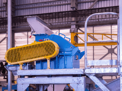
A Hammermill is a device that can instantaneously grind various raw materials by feeding them through a hopper and rotating a hammer installed on the rotor at high speed, thereby impacting the fed materials.

The hammer part can be a movable or fixed type, and the rotation speed can be changed to change the particle size of the material. The screen part is attached to the outlet after processing and used as a filter, and by changing the mesh of the screen, the particle size can be uniformly adjusted.

Therefore, by changing the combination of hammers and screens, the mill can be used for a wide variety of applications.

Uses of Hammermills

Hammermills are used for fine grinding, i.e., to grind particles of a few centimeters to a size of 10 to 1 micron. Hammermills are used for a wide variety of applications, ranging from the processing of building materials to food and pharmaceuticals.

There are different types of hammermills, depending on their purpose and use. Hammermills with fixed hammers are used for grinding and processing raw materials, and are suitable for soft materials such as grains, or when the required load is small and the rotation of the hammer is low.

Hammermills with movable hammers are suitable for hard materials such as ores and wood, or when a large impact is required for crushing.

Principle of Hammermill

Hammermills grind by rotating the hammer at high speed and swinging the hammer to impact the object to be processed. Therefore, the impact can be adjusted according to the material and application of the object by the rotation speed of the hammer and the swinging motion.

A screen is installed at the outlet of the crushed workpiece to adjust the particle size after processing to ensure consistent quality. Although the machine is noisier and vibrates more, it is characterized by its high crushing capacity and ability to process relatively hard materials.

In addition, its simple structure makes it easy to disassemble, reassemble, replace parts, and perform other maintenance. In addition, the use of super steel makes it possible to take countermeasures against wear, so it has a long service life and can be used for a long period of time.

Cautions for Hammermills

Hammermills have a simple structure and can be used to grind various types of materials, but there are some points to note. Hammermills are suitable for hard, brittle, and easily broken materials because the impact force of the hammer crushes the sample. On the other hand, elastic or fibrous materials such as plastics cannot be crushed very finely.

In addition, for not only hammermills, but also other dry mills, it is difficult to grind materials with water or oil content, such as food, because they stick to the equipment or clog the screen. In addition, hammermills can heat up when operated for long periods of time, so care must be taken when grinding heat-sensitive samples.

Thus, it is important to select the appropriate milling machine depending on the sample to be milled, since the appropriate milling mechanism varies depending on the material characteristics.

カテゴリー
category_usa

Centrifuge Tubes

What Is a Centrifuge Tube?

Centrifuge Tubes

Centrifuge tubes, also known as stitches, are containers used in experiments and tests in which liquids are separated from each other or solids and liquids are separated using a centrifuge.

Glass or plastic is used as the material, and you can choose one that is resistant to impact and strength, one that is cold- or heat-resistant and suitable for temperature changes, or one that is chemical-resistant, depending on the intended use.

There are also those with scales, those that can be written on the container, and those with a tight-sealing cap.

Uses of Centrifuge Tubes

1. Use With Centrifuges

A centrifuge is used to collect insoluble substances as precipitates by centrifuging a suspended sample in a centrifuge tube, which has the shape shown in Figure 1. The centrifuge is a device that rotates a rotor, to which the centrifuge tube can be set, at high speed. Centrifugal force can separate liquids and solids, or liquids with different specific gravities.

2. Use for Sample Collection and Preservation

Centrifuge tubes with a screw-type cap structure are sometimes used to collect, transport, and store samples that require delicate handling due to their excellent sealing and preservation properties.

In the field of biochemical experiments, they are also used to separate cells collected as precipitates by centrifugation or to extract nucleic acids from cells and can be used to preserve and fine-tune each component.

Characteristics and Principles of Centrifugation Using a Centrifuge Tube

1. Separation of Liquid Components With Different Specific Gravities

Centrifugal separation is the separation of substances with different specific gravities by centrifugal force. The centrifugal force generated by high-speed rotation can reduce the time required for the sedimentation of substances that would otherwise take a long time to settle naturally. Since liquid components with heavier specific gravity settle faster than those with lighter specific gravity, multiple liquid components with different specific gravity can be separated as liquid phases in a centrifuge tube according to their specific gravity.

2. Separation of Insoluble Material From Suspension

When a substance is dispersed in a liquid without dissolving, it is called a suspension. To separate insoluble components from such a sample, the suspension is injected into a centrifuge tube and subjected to centrifugal separation, where only the insoluble components are obtained as precipitates. Therefore, this method is used to recover minute amounts of fine insoluble substances contained in the suspension. For example, in experiments using microorganisms or cells, it is used to separate only the cells from the culture medium.

3. Emulsion Separation

A liquid in a state of dispersion of immiscible liquids such as water and oil is called an emulsion. Familiar examples include milk and mayonnaise. Centrifugal separation is also used to separate each liquid component from such liquids.

Structural Features of Centrifuge Tubes

1. Strength

The main uses of centrifuge tubes are to seal the sample inside the tube and to use it as a container to set the sample in a centrifuge, which involves strong physical stimulation. Therefore, the centrifuge tube has a structure that can withstand centrifugal force, is hermetically sealed, and has excellent strength to prevent cracking even under load.

2. Shape

The centrifuge tube has a narrow tip to allow insoluble components to precipitate at high density and in a narrow surface area. Thanks to this unique shape, insoluble components can be efficiently collected at the bottom of the centrifuge tube. There are various types of centrifuge tubes on the market, some of which have scales engraved on the tube or are made of a material that is easy to write on the sides or cap to prevent the scales from disappearing due to rubbing, etc. Some of them have scales engraved on the tube molding.

カテゴリー
category_usa

Chemical Protective Clothing

What Is Chemical Protective Clothing?

Figure 1. Overview of protective clothing

Figure 1. Overview of protective clothing

Chemical protective clothing is protective clothing worn to ensure the safety of workers and protect their health when handling hazardous chemical substances.

Protective clothing should be worn when engaged in work involving the handling of acids, alkalis, organic chemicals, and other gaseous, liquid, and particulate chemical substances (hereinafter referred to as chemical substances).

Unlike ordinary clothing, the surface gaps are very small and smooth. The materials used also have extremely low permeability to organic solvents. Although originally manufactured to protect against chemical substances, it is also used to protect against biological and radioactive materials due to its high particulate protection effectiveness.

Uses of Chemical Protective Clothing

The main uses of chemical protective clothing are in workplaces where chemical substances are handled, in the event of a disaster caused by nuclear, biological, or chemical substances, and in workplaces where hazardous substances must be disposed of.

Examples of past large-scale disasters include the following:

  • Investigating chemical attacks
  • Asbestos treatment work
  • Dioxin and PCB treatment work
  • Disinfection and dismantling of chicken coops contaminated with avian influenza

Chemical protective clothing is usually used to protect against harmful substances to the human body, but it can also be used to protect workers from contamination.

Examples include metalworking industries where grease and soot stains are common, and painting and printing industries where paint and ink are used.

Other applications include clean rooms in regenerative medicine research, where protective clothing is used to protect cells and drug products from bacteria that may be attached to the worker’s body.

Principle of Chemical Protective Clothing

Figure 2. Various materials used in protective clothing

Figure 2. Various materials used in protective clothing

Chemical protective clothing is made of a variety of textile materials, including non-woven fabrics, SMS, FS, and Tyvek®. It is very important to wear protective clothing of the appropriate standard for the intended event.

1. One-Layer Non-Woven Fabric Type

This product is made of spunbond polypropylene. The single-layer structure of spunbonded polypropylene fabrics allows for a large number of voids between fibers. Although the barrier property is somewhat inferior, it is inexpensive and suitable when cost is important. It is sufficient for light soiling.

2. SMS

SMS polypropylene is used for this product. It has a three-layer structure consisting of spunbonded, meltblown, and spunbonded materials. It is characterized by strong abrasion resistance and a cloth-like feel. Although relatively inexpensive, it is resistant to abrasion and light soiling, and has a high barrier effect against dust and droplets.

3. FS

This product uses a film laminate. It has a structure in which a thin film material is attached to the surface of polypropylene, spun-bonded nonwoven fabric, or the like. It has high barrier properties against dirt and dust, and excellent waterproofing properties, making it suitable for work in watery areas.

4. Tyvek

Tyvek is a special material unique to DuPont, consisting of continuous microfibers of high-density polyethylene (0.5~10 microns) bonded together by heat and pressure, which provides excellent barrier properties against particles of 1 micron or less. Two-layer protective clothing with polymer coating is also available.

Types of Chemical Protective Clothing

Figure 3. Full Body Chemical Protective Clothing and Partial Chemical Protective Clothing

Figure 3. Full Body Chemical Protective Clothing and Partial Chemical Protective Clothing

There are two types of chemical protective clothing: full body chemical protective clothing, which protects the entire body or a large part of the body, and partial body chemical protective clothing, which protects a part of the body.

Full-body chemical protective clothing can range from airtight suits with self-contained breathing apparatuses inside, to full-body suits that are sealed against liquids and chemical mists.

Partial chemical protective clothing includes aprons, footwear covers, lab coats, arm covers, and smogs.

カテゴリー
category_usa

Hexagon Nuts

What Is a Hexagon Nut?

Hexagon Nuts
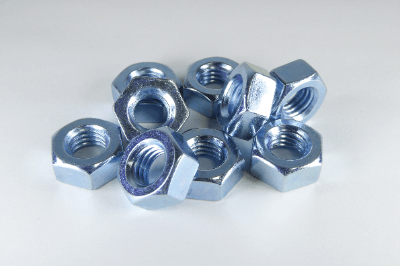
Hexagon Nuts are a fastening part with a hexagonal outer shape and a threaded center hole. Generally, Hexagon Nuts are not used by themselves, but are inserted between parts to be fastened, and screwed into threaded parts such as bolts.

ISO Standard

  • ISO 4032:2012 Hexagon regular nuts (style 1) – Product grades A and B
  • ISO 4033:2012 Hexagon high nuts (style 2) – Product grades A and B
  • ISO 4034:2012 Hexagon regular nuts (style 1) – Product grade C
  • ISO 4035:2012 Hexagon thin nuts chamfered (style 0) – Product grades A and B
  • ISO 4036:2012 Hexagon thin nuts unchamfered (style 0) – Product grade B
  • ISO 8673:2012 Hexagon regular nuts (style 1) with metric fine pitch thread – Product grades A and B
  • ISO 8674:2012 Hexagon high nuts (style 2) with metric fine pitch thread – Product grades A and B
  • ISO 8675:2012 Hexagon thin nuts chamfered (style 0) with metric fine pitch thread – Product grades A and B

Principles of Hexagon Nut

Hexagon Nuts tighten and secure parts using the threaded fastening principle. By turning the hexagon nut, the nut and bolt contact the part to be fastened, and then tightening the nut further, the following forces are exerted.

  • Compressive force (force that pushes in the direction of the axis of the clamp) on the part to be clamped
  • Tensile force (reaction force of the part to be fastened) on a screw such as a bolt

As a result, the following frictional forces are generated and the screw remains tightened without loosening.

  • Between the male thread and female thread
  • Seat surface of the bolt and nut (surface in contact with the part to be fastened)

Uses of Hexagon Nuts

Nuts come in a variety of shapes and types, but hexagonal nuts, in particular, are probably the most commonly used for fastening parts.

Hexagon Nuts are used in a very wide variety of situations, from general purpose to special applications, from very small parts to large parts, from very small parts such as precision instruments to household DIY, railroad tracks, and general industrial equipment and facilities.

Hexagon Nuts are characterized by their hexagonal shape, which allows tools such as wrenches and wrenches to be hung on them at 60-degree intervals, allowing them to be tightened at small angles. They are also very easy to use since many general-purpose tools are compatible with them.

Types of Hexagon Nuts

There are a wide variety of locks that have anti-loosening functions, and their respective functions and features must be used effectively. In addition to the above, there are many other types of products, including standard products, special-purpose and specially designed products.

How to Use Hexagon Nuts

If Hexagon Nuts are not used properly, the bolts on the mating side may be damaged, or products or equipment assembled with hexagon nuts may be damaged.

To prevent this, the following points must be observed:

  • Tightening force must be within the allowable range to prevent damage to the hexagon nut and bolt.
  • Repeated forces (e.g., vibration) applied to the hexagon nut and bolt must be within the allowable range.
  • The seating surfaces of the hexagon nut and bolt (the surfaces that come into contact with each other, not the surfaces that the tool touches) must be within the allowable range. The seating surfaces of the hexagon nut and bolt (the surfaces that contact each other, not the surfaces that the tool touches) must not cause the object to be tightened (metal, wood, etc.) to cave in.
  • Tightening the hexagon nut and bolt must not damage the object to be tightened.

Other Information on Hexagon Nut

1. Material and Surface Treatment of Hexagon Nut

Hexagon Nut materials, mainly iron, alloy steel, stainless steel, titanium alloy, copper and copper alloy, aluminum and aluminum alloy, nickel alloy, etc. Generally, materials are selected according to requirements such as strength and corrosion protection.

When a bolt or nut is subjected to a heavy load or used in equipment where human life may be at stake, the material of the hexagon nut has a significant impact on its strength, so it is necessary to select a material with sufficient strength requirements.

The presence or absence of measures against corrosive environments is also an important factor in material selection. Material selection should be based on the corrosive environment so that the hexagon nut does not lose weight and strength due to corrosion.

Electrical corrosion is also an important factor. If the material of the hexagon nut differs from the material of the mating mechanical element or the object to be fixed, a difference in metal potential may result in corrosion. Particular attention should be paid in the case of aluminum and stainless steel.

The following surface treatments are available for hexagon nuts, which are selected according to appearance quality and price:

Electroless nickel, trivalent chromate, unichromate plating, zinc plating, chromate plating, nickel plating, chrome plating, parker, dacrotized, paint/coating, silver, copper, tin plating, etc.

2. Preventing Hexagon Nuts From Loosening

The following measures can be taken to prevent loosening of hexagon nuts:

Initial loosening measures
A spring washer or disc spring washer is inserted between the hexagon nut and the part to be fastened. This function compensates for the initial reduction in axial force and has no effect on preventing slippage of the seating surface, thus it cannot prevent loosening due to the nut’s return rotation.

Countermeasure against reduction in axial force (non-return stop)

  • Mechanical anti-rotation method
    To prevent the nut from turning, the following parts are used to secure the nut to the threaded side.
    Example: grooved lock nut + split pin, lock nut with external teeth, wire lock, etc.
  • Incremental return torque method
    This method increases the resistance to rotation between the male and female threads in order to prevent loosening by using the following parts.
    Example: Nylon insert locknut, ring locknut, flex locknut (slit nut), flange nut (with serration), etc.
  • Return Rotation Prevention (Loosening Prevention)
    1. This method increases friction between the male and female threads to prevent the nut from rotating back. Double nuts are applicable.
    2. This method applies an adhesive or other substance to the threaded part to adhere it. Anaerobic adhesive application, screws with adhesive, etc. fall under this category.
    3. This method uses two types of nuts with eccentric, wedge-shaped concavities and convexities. The entire thread of the convex nut is pressed against the bolt side, and the entire thread of the concave nut is pressed against the threaded portion of the bolt on the opposite side. The “wedge” effect is utilized. Hard locknuts fall into this category.
カテゴリー
category_usa

Graduated Cylinders

What Is a Graduated Cylinder?

Graduated Cylinders
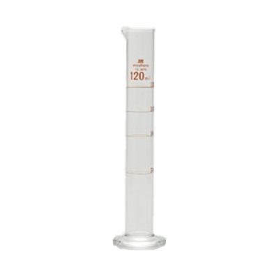
A graduated cylinder is a laboratory instrument used to measure the volume of a liquid. It is cylindrical, and equipped with a scale on the side. The volume is read visually at the lowest point of the meniscus, which forms at the surface of the liquid in the cylinder.

It’s important to avoid using abrasive materials for cleaning the cylinder as they can scratch the interior, leading to minor volume discrepancies.

For measuring organic solvents, it’s advised to use a glass cylinder, as plastic ones can dissolve or swell due to certain solvents. A glass cylinder is recommended in such cases.

Uses of Graduated Cylinders

A graduated cylinder is a laboratory instrument used to measure the volume of liquids in chemistry experiments. They are also a staple in educational settings for simple, hands-on science experiments.

The capacity of graduated cylinders typically ranges from 10 mL to 1 L. The volume per scale division and the associated measurement error vary depending on the cylinder’s capacity. The material of the cylinder is glass or resin.

Usage and Accuracy of Graduated Cylinders

A graduated cylinder is an elongated cylindrical container with a scale on it. To ensure an accurate reading, place the cylinder on a level surface and observe the scale at the meniscus’s bottom.

The accuracy of the graduated cylinder is determined by the fineness of the scale. For precise measurements requiring higher accuracy, a volumetric flask is recommended over a graduated cylinder. See more on measuring flasks.

How to Clean a Graduated Cylinder

Clean it using a solvent that can dissolve the contents or residue. Avoid abrasive materials during cleaning to prevent scratching the glass, which could affect volume measurements.

For resin cylinders, use water or a solvent that is chemically compatible with the resin to prevent alterations in volume due to swelling or dissolution. Cleaning with organic solvents such as acetone may cause volume changes in resin cylinders.