カテゴリー
category_usa

Electrolyzed Water Generator

What Is an Electrolyzed Water Generator?

Electrolyzed Water Generators

An electrolyzed water generator is a device that generates electrolyzed water by electrolyzing salt water or other liquids.

The two largest categories of electrolyzed water are hypochlorite water, which is acidic electrolyzed water, and alkaline electrolyzed water. Acid electrolyzed water is further classified into strongly acidic electrolyzed water, weakly acidic electrolyzed water, and slightly acidic electrolyzed water according to pH.

Acid electrolyzed water (hypochlorite water) is used for sterilization and cleaning, while alkaline electrolyzed water is particularly effective in cleaning lipids and proteins. Strongly acidic electrolyzed water, weakly acidic electrolyzed water, and slightly acidic electrolyzed water that meets the requirements of various laws and regulations can be used as food additives and agricultural chemicals that can be used on organic agricultural products.

This is because electrolyzed water is very safe as long as it complies with regulations. Electrolysis generators are widely used in fields and sites where sanitation is required.

3509_Electrolyzed-Water-Generators_電解水生成装置-1.png

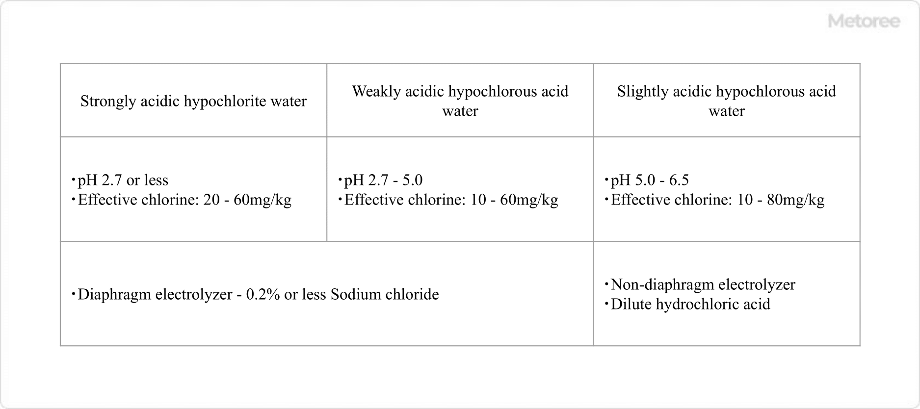
Figure 1. Types of acidic electrolytic water

Uses of Electrolyzed Water Generators

Because of the excellent sterilizing and cleaning effects of electrolyzed water, electrolyzed water generators are widely used where hygiene control is required. Specifically, they are used in the food industry, medical industry, childcare and nursing care industry, and cleaning industry.

For example, applications in food factories and restaurant kitchens include the cleaning and sterilization of equipment and utensils, and the sterilization of food ingredients. Major applications in the medical industry also include sterilization and cleaning of medical equipment in hospitals.

In childcare and nursing care facilities, the use of sanitizers in various aspects of maintaining a hygienic environment includes washing baby bottles and tableware, hygienic hand washing, and sterilizing and cleaning by wiping down the facility.

Factories that handle metal or plastic parts may use electrolyzed water generators, especially for the purpose of rust prevention with alkaline electrolyzed water. This application takes advantage of the fact that alkaline electrolyzed water is excellent for removing protein and lipid-based stains.

Principle of Electrolyzed Water Generators

3509_Electrolyzed-Water-Generators_電解水生成装置-2.png

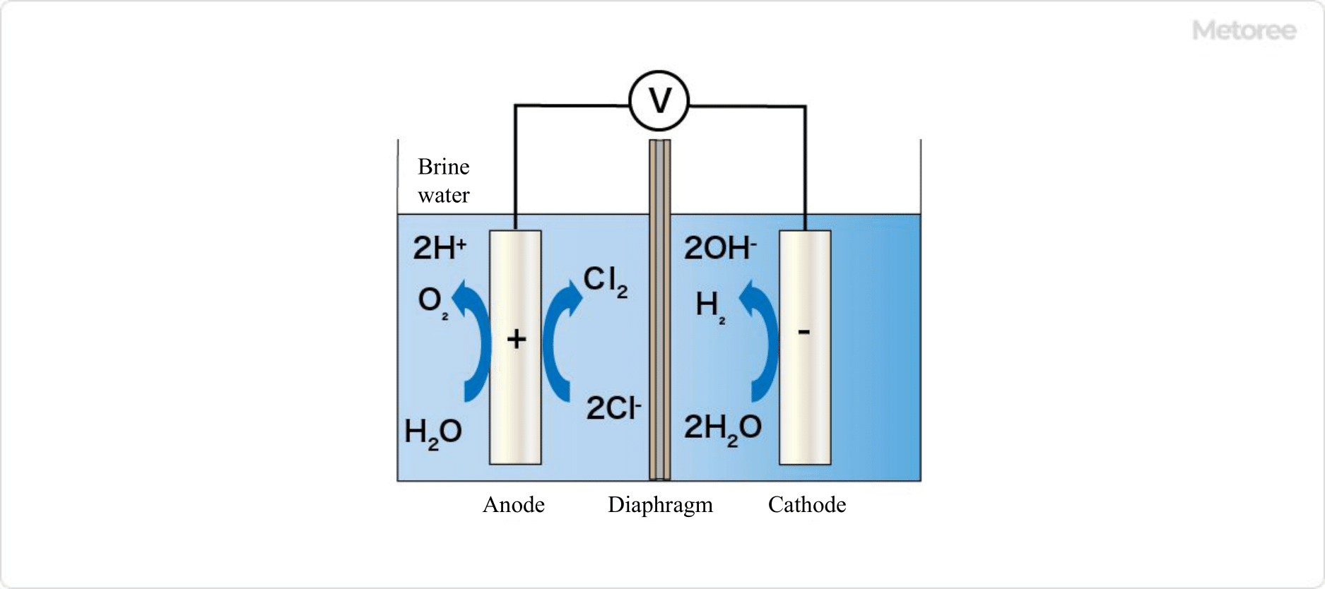
Figure 2. Overview of strongly acidic electrolytic water generator (two-diaphragm type)

There are two types of electrolyzed water: acidic electrolyzed water, such as hypochlorite water, and alkaline electrolyzed water. Most electrolyzed water generators have a dual-chamber electrolyzer structure with the anode and cathode separated by a diaphragm (two-diaphragm type).

When raw water, such as tap water, to which a small amount of salt such as hydrochloric acid or potassium chloride is added, is electrolyzed in the electrolyzer, the generated ions are separated by the diaphragm. The acidic electrolyzed water generated in a two-chamber electrolysis tank is mainly strongly acidic electrolyzed water.

When salt water is electrolyzed, the following reactions occur at the anode in the electrolyzer.

  • H2O → O2 + 2 H+
  • 2Cl- + 2e- → Cl2

When the generated chlorine molecules react with water, hypochlorite water, or acidic electrolyzed water, is generated. The electrolyzed water produced at this time is strongly acidic electrolyzed water.

On the other hand, the reaction that occurs on the cathode side is as follows:

  • H2O → H2 + OH-

Because the cathode side is separated from the anode side by a membrane, the concentration of hydroxide ions (-OH) increases. As a result, alkaline electrolytic water is produced.

Types of Electrolyzed Water Generator

3509_Electrolyzed-Water-Generators_電解水生成装置-3.png

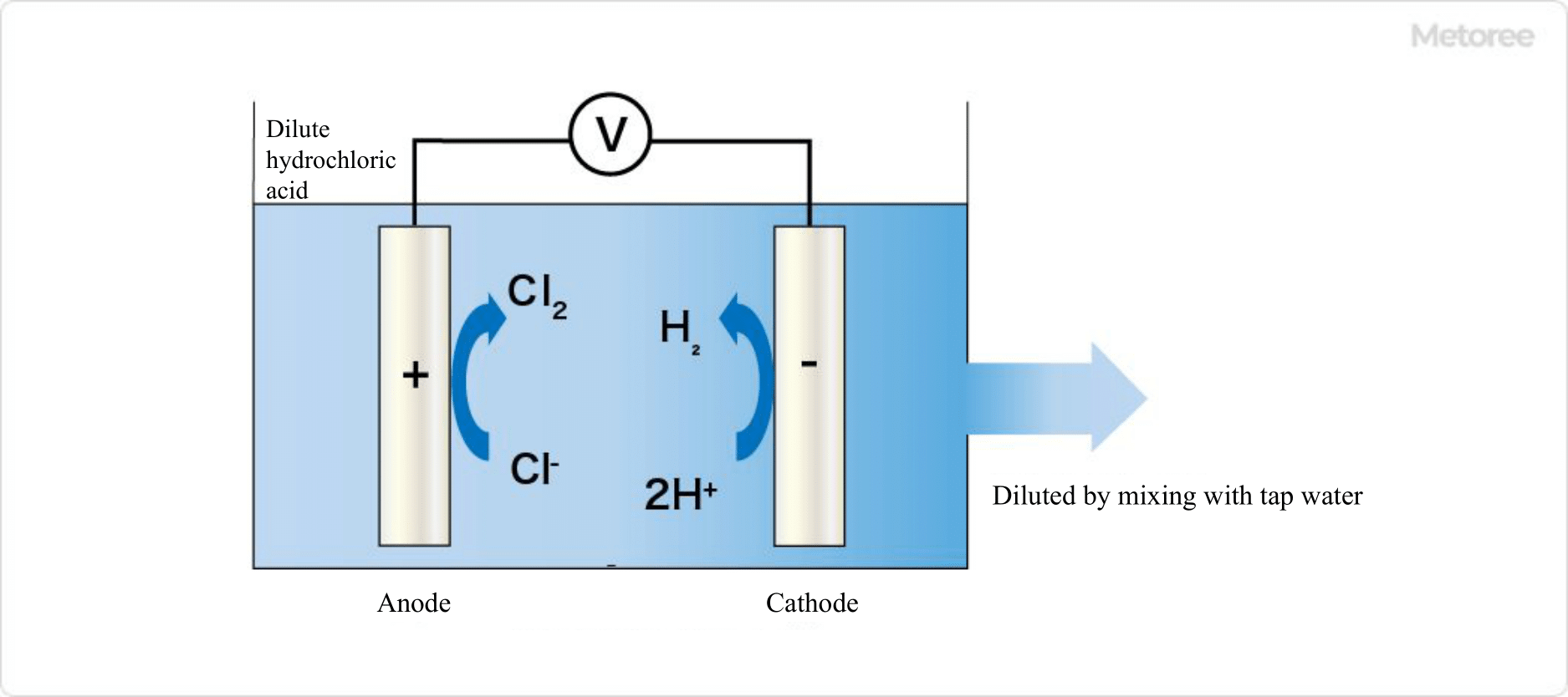
Figure 3. Overview of microacidic electrolyzed water generator

Electrolyzed water generators can be classified according to their structure and the intended electrolyzed water.

1. Classification by Structure

In addition to the two-chamber electrolyzed water generator mentioned above, there is a one-chamber electrolyzed water generator that produces slightly acidic electrolyzed water. Like strongly acidic electrolyzed water, slightly acidic electrolyzed water is approved as a food additive and is defined as “produced water with a pH of 5.0 to 6.5 and an effective chlorine concentration of 10 to 30 ppm obtained by electrolyzing 2 to 6% hydrochloric acid in a non-diaphragm electrolysis tank.

It is characterized by a lower effective chlorine concentration than strongly acidic electrolyzed water and a high sterilizing power at a near-neutral pH. It is widely used for cleaning and sterilizing various types of food and kitchen utensils. Because of its low effective chlorine concentration, it is particularly suitable for cleaning cut vegetables and fruits. The one-chamber electrolyzer is a system in which hydrochloric acid, previously prepared at 2-6%, is directly electrolyzed and then mixed with raw water to generate it.

Chlorine gas (Cl2) is generated by electrolysis of hydrochloric acid at the anode in the electrolyzer, and hydrogen gas (H2) is generated at the cathode. The generated chlorine molecules react with water to produce hypochlorite water, or acidic electrolyzed water, which is diluted to the desired concentration by mixing with raw water.

2. Classification by Electrolytic Water

When classified by electrolytic water, there are three:

  • Strongly acidic electrolyzed water generator
  • Slightly acidic electrolyzed water generator
  • Alkaline electrolyzed water generator

As indicated in the principle of section, the mechanism of the device itself is the same, since strongly acidic electrolyzed water and alkaline electrolyzed water are generated simultaneously by a single electrolysis. Note, however, that some products drain alkaline electrolytic water and use acidic electrolytic water exclusively.

In addition, there are various sizes and shapes, including large stationary type products that can be used in factories, under-counter type stationary type products, and small water supply unit type products that can be hung on the wall.

カテゴリー
category_usa

Rust-Proof Paper

What Is Rust-Proof Paper?

3487_Rust-Proof-Papers_防錆紙_-1.png

Figure 1. Image of anticorrosion paper

Rust-proof paper is a wrapping paper with a rust-preventive function.

Rust-proof paper is manufactured by coating or impregnating kraft paper with a vaporizable chemical substance (rust-proofing agent) that prevents rust (corrosion) of metals. By simply wrapping the metal or other product to be protected from rust with rust-proof paper, the object can be easily protected from rust.

The paper can be freely transformed according to the size and shape of the object, and can be easily used for everything from simple wrapping to sealed packaging.

Uses of Rust-Proof Papers

Rust-proof paper is used to protect and preserve objects from rust for a long period, for example, when the object is made of rust-prone materials or in an environment where rust is likely to occur. It is used in industries that handle metals, such as steel and automobiles, where rust can cause quality problems.

Rust-proof paper with a barrier layer and moisture-proofing properties is also commercially available, and when using such rust-proof paper, moisture-proof packaging is not necessary. In addition to direct wrapping, the paper can be placed in a sealed space, such as a polyethylene bag or a moisture-proof cardboard box, to prevent rust.

Principle of Rust-Proof Papers

3487_Rust-Proof-Papers_防錆紙_-2.png

Figure 2. Principle of anti-rust paper

Rust-proof paper prevents rust through a chemical action. When the rust inhibitor vaporized from rust-proof paper is adsorbed on the metal surface, it exerts its rust-preventing effect. The principle of how rust-proof paper prevents metal from rusting is as follows:

  1. The rust-proof paper gradually vaporizes (sublimates) at room temperature, and the vapor quickly fills the sealed space between the paper and metal.  
  2. The vaporized rust inhibitor dissolves in the moisture on the metal surface. The dissolved rust inhibitor is physically and chemically adsorbed as molecules or ions to form a “rust inhibiting film.  
  3. The rust-preventive film shields the steel from the outside air, which causes rust, and prevents it from changing into rust.

The rust-preventive film of this vaporizable rust-preventive agent is extremely thin, on the nanometer order of thickness, and has weak adsorption power, so it does not cause any change in the appearance of the metal surface. After rust-preventive packaging, metal products can be used immediately without cleaning the surface. In addition, because it is a rust inhibitor that uses vaporization, it is expected to have an immediate effect.

Rust-proof paper uses a chemical reaction, so unlike rust-preventive oil, which prevents rust through physical action, it cannot be expected to have the same effect on all metals, which can be considered a disadvantage. It is important to select the most suitable rust-proof paper for the product to be packaged.

It is also necessary to clean the product to be packaged before wrapping it in rust-proof paper. Rust-proof paper does not remove dirt, so it may be difficult for the rust inhibitor to reach the product if dirt remains on the paper.

Types of Rust-Proof Paper

Rust-proof paper can be classified in two ways: by the metal to be rust-proofed, i.e., the rust-proofing agent component, and by the packaging form, i.e., the base packaging paper part.

1. Classification by Rust-Preventive Metals/Rust-Preventive Agent Components

3487_Rust-Proof-Papers_防錆紙_-3.png

Figure 3. Types of Anti-Corrosion Paper and Whether Metals Can Be Used

Since there is no rust inhibitor that is effective on all metals, it is necessary to use rust-proof paper that contains the appropriate rust inhibitor for the target metal. To give an example, rust-proof paper specifically designed for steel is not effective on copper.

Rust-proof paper for ferrous/non-ferrous metals has been developed that can be used when steel and copper coexist, but it will be less effective than using one specifically for each metal.

2. Classification by Wrapping Paper Material

When rust-proof paper is used for wrapping, it must be strong enough to withstand wrapping operations and handling after wrapping. Basically, kraft paper (40-100 m2) of a thickness appropriate for the uses of the paper is used. However, when the paper is inserted into a sealed space, it does not require any particular strength, so using a paper with a thinner thickness is not a problem.

In addition, when packaging slit coils, etc., rust-proof paper based on crepe paper (wrinkled paper) provides an excellent fit.

カテゴリー
category_usa

Mixed Signal Oscilloscope

What Is a Mixed Signal Oscilloscope?

A mixed signal oscilloscope is a digital oscilloscope with an analyzer function.

The latest digital oscilloscopes are increasingly equipped with logic input functions and can display both analog and digital signals, which are called mixed signal oscilloscopes, to distinguish them from ordinary oscilloscopes. Mixed signal oscilloscopes display the signal waveform from the analog input channel and the logic waveform from the digital input channel on a single display, allowing the two to be compared on the same time axis.

Uses of Mixed Signal Oscilloscopes

Mixed signal oscilloscopes are used for signal analysis, especially for circuits with mixed analog and digital signals. Conventionally, an oscilloscope is used to observe analog signals and a logic analyzer is used to observe digital signals, and measurements are made by combining these two instruments.

For example, by triggering a digital signal from a logic circuit at the timing when the signal shows a specific status, the signal waveforms of the analog circuit before and after the trigger can be observed. It is also an extremely effective measuring instrument for analyzing troubles that occur at specific timing in high-speed digital circuits, using an oscilloscope to observe the waveform of digital signals to determine if there is a rise time delay or overshooting/undershooting.

Principle of Mixed Signal Oscilloscopes

A mixed signal oscilloscope is a measurement instrument that incorporates the functions of a logic analyzer into a digital oscilloscope, integrating the two to enable acquisition of waveform data. Both functions capture data based on a common time axis, so the timing of analog signal waveforms and digital signals of logic circuits are perfectly matched.

The standard specifications for analog inputs are 4 to 8 channels with 8 to 12 bit resolution, while digital inputs are 16 or more channels and are treated as 1-bit signals. The memory length varies from model to model, but the larger the memory length, the more advantageous it is in terms of measurement. In general, digital signals can acquire data for a longer period.

The analog signal waveform and digital signal are displayed on the display with a common time axis, so the relationship between the two can be clearly seen at a glance, which is very effective for analyzing circuit operation. Some models use an operating system such as Windows 10, which inherits the operability of PCs and tablets, making it possible to work more efficiently.

More About Mixed Signal Oscilloscopes

Useful Features Specific to Mixed Signal Oscilloscopes

The following is an example of a useful feature unique to mixed signal oscilloscopes that can be used to analyze the circuitry of a memory device. The commands output from the controller to memory are defined as a combination of RAS, CAS, and WE signals, and by using symbols instead of signal names, you can display not only “Hi” and “Lo” logic waveforms but also “Read” and “Write” symbols, This is very useful for signal analysis.

Furthermore, by setting a “Read” or “Write” pattern as a trigger condition, you can observe the signal waveforms of the data or address at that time on the oscilloscope. Conversely, if an abnormal waveform input to the oscilloscope is set as the trigger condition, it is possible to check the sequence in which the phenomenon occurs.

Another example is to deal with the shortage of channels in a normal oscilloscope. The extra logic channels cannot be used to observe waveforms, but can be set for trigger input or timing checks. Therefore, the oscilloscope channels can be effectively utilized because they can be assigned only to signals whose waveforms are to be observed.

カテゴリー
category_usa

Portable Vibration Meter

What Is a Portable Vibration Meter?

Portable vibration meters are portable vibration meters that perform vibration measurement and vibration analysis of machinery.

They are compact and lightweight and feature a panel and buttons for easy and convenient measurement. This makes it easy to use immediately on site. Vibration is a major factor in causing structures and machinery to break or stop abnormally. With portable vibration meters, vibration measurement and analysis can be easily performed without the need for advanced technology.

Uses of Portable Vibration Meters

3710_Portable-Vibrometers_ポータブル振動計-1.png

Figure 1. Vibration measurement of a three-phase motor using a portable vibrometer

Portable vibration meters are used to inspect industrial machinery such as three-phase motors and for product inspection and testing on product lines.

Vibrometers may be directly attached to equipment for constant monitoring, or they may be installed stationary in shipping or transportation environments for inspection or R&D. Portable vibration meters are specialized for portability and are used in patrol monitoring, inspection, and maintenance.

Principle of Portable Vibration Meters

There are two main measures of vibration: “frequency” and “amplitude,” and the vibration is measured by processing these measurements.

  • Frequency (ESP. Of Waveforms): The frequency at which the vibration is occurring
  • Amplitude (Of Vibration): The magnitude of the vibration swing

To perform the measurement process, vibrations are first measured at a fixed sampling period and converted from these values into an electrical signal. In most cases, this electrical signal is amplified by an amplifier and processed to a value that is easily measured by an A/D converter.

Using these vibration values, a filtering process is applied to remove noise and measure the exact level of vibration. This gives us the frequency and amplitude at which the object is vibrating.

FFT analysis is often used to measure machinery that is experiencing abnormal vibration.

These processes are then visualized by means of waveform graphs and numerical values, converted into easily recognizable values, and displayed on a monitor. Portable vibration meters are small but retain multiple functions, such as efficiently displaying numerical values on a monitor screen and transferring data to a PC via a Wi-Fi connection or SD card.

Types of Portable Vibration Meters

There are two main types of portable vibration meters: contact and non-contact.

1. Contact Type Portable Vibration Meter

3710_Portable-Vibrometers_ポータブル振動計-2.png

Figure 2. Contact-type portable vibrometer

A contact-type portable vibration meter, such as the one shown in Figure 2, is equipped with an accelerometer. The accelerometer is attached directly to the machine and measures its vibration. The advantage of contact-type portable vibration meters is that they are relatively inexpensive and compact.

2. Non-Contact Type Portable Vibration Meter

3710_Portable-Vibrometers_ポータブル振動計-3.png

Figure 3. Portable vibrometer of non-contact type

A laser Doppler vibrometer is often used as a non-contact type portable vibration meter. A laser beam is irradiated onto an object, and the Doppler effect of the light is used to measure the vibration of the object.

The advantage of the non-contact type portable vibration meter is that it can measure vibrations without contact, making it possible to measure rotating objects such as motor shafts.

カテゴリー
category_usa

Handy Scope

What Is a Handy Scope?

Inspection Cameras

A handy scope is a microscope that can be held by hand.

It is also called a hand-held microscope. It can project a magnified object on a screen such as a PC or monitor, allowing observation without looking through the lens as with a regular microscope.

Since the scope part can be held, it is possible to observe an object that cannot be observed on a stage by bringing the lens directly close to the object. For observation in more confined spaces, an endoscope-type product called a micro handy scope is used.

Uses of Handy Scopes

The uses of handy scopes are diverse. They are used in a wide range of fields because they can be easily angled with one hand for easy observation.

It can easily inspect cracks in pipes and tanks, dirt and clogged metal filters, and the inside of hard-to-reach spaces, machines, pipes, and ducts. The lightweight and one-handed operation makes it easy for anyone to work anywhere.

Principle of the Handy Scopes

A handy scope has a longer cable section than a typical microscope. A microscope is called a microscope in English, and a microscope and a microscope are the same thing. However, in Japan, the type with two lenses (an eyepiece and an objective lens) is called an optical microscope, while the type with one lens is called a microscope.

The magnification of an optical microscope is determined by the product of the magnification of the eyepiece and objective lens. On the other hand, the magnification of a handy scope is determined by the product of the magnification of the objective lens, the magnification of the digital camera, and the magnification of the monitor.

The structure of the handy scope does not allow for viewing with both eyes, as is the case with an optical microscope, making it difficult to see three-dimensional objects.

Structure of Handy Scopes

A handy scope consists mainly of an optical lens, a camera, and a light source lamp and cable. Cables are connected to dedicated information processing equipment, PCs, monitors, and other devices.

Some types of handheld scopes have auto-focusing (automatic focus adjustment function) and light intensity adjustment functions.

How to Select a Handy Scope

The requirements for a handy scope vary depending on the object to be observed, the frequency of use, and the required image quality.

1. Magnification

The magnification of the lens of a handy scope should be selected according to its purpose. There is a wide range of magnifications that can be used for observation, but the higher the magnification, the narrower the field of view and focal range, making it more difficult to find the object.

Especially at magnifications of 100x or more, it is difficult for human handlers to focus on an object, and this is where depth composite technology becomes necessary. Depth composite technology is a function that combines images in focus at multiple depths into a single image. When using high magnification, it is necessary to select a handy scope that is equipped with the depth composite function.

2. Focus Function

Handy scopes are handheld, which inevitably causes camera shake. Especially when magnification is high, even a small camera shake can cause a large shift in focus. Since it is cumbersome and burdensome to focus each time during work, a product with an auto-focus function is recommended when the magnification is high or when the scope is used for a long period.

3. Resolution

Since the handy scope is equipped with a camera, the number of pixels in the camera also affects the image quality. The larger the number of pixels and data, the more detail can be seen in the image, but care should be taken because the storage capacity becomes larger.

カテゴリー
category_usa

Nano Bubble Generator

What Is a Nano Bubble Generator?

A nano bubble generator is a device that generates very small bubbles called ultrafine bubbles.

The nano bubble generator produces nano bubbles, which have the ability to sterilize, clean, purify the environment, promote growth, improve immunity, and protect cells.

Uses of Nano Bubble Generators

The main uses of nano bubbles, taking advantage of their properties, are as follows:

  • Sterilizing and Cleaning Power
    Hospitals and nursing homes
  • Environmental Cleanup
    Wastewater treatment of general and industrial wastewater, purification of rivers, ponds, and seawater, etc.
  • Ecological Activation, Cell Protection, Growth Promotion
    Maintaining freshness of fish, shellfish and crustaceans such as oysters and shrimp, and fish farming.

In addition, nano bubbles also have the effect of promoting water evaporation, which can be used to improve the efficiency of water-cooled cooling towers. They are also used to lower the temperature of liquids efficiently by utilizing their heat transfer capability.

Principle of Nano Bubble Generators

Nano bubble generators generate nano-sized ultrafine bubbles. Generally, bubbles less than 50 micrometers in diameter are called nano bubbles.

Nano bubbles are characterized by the fact that the ionic force causes the gas-liquid interface to shrink, concentrating the ion concentration and increasing the temperature and pressure inside the bubble, resulting in the development of various phenomena. There are two types of nano bubble generators: those that generate nano bubbles together with micro bubbles, which are larger than nano bubbles, larger than 50 micrometers in diameter and about 0.1 mm or less, and those that directly generate nano bubbles.

Types of Nano Bubble Generators

For nano bubble generators, there are “high-speed swirling liquid flow type” and “pressurized dissolution type” that generate micro bubbles and nano bubbles at the same time. Surfactant-added micropore type” and “ultrasonic cavitation type” generate only nano bubbles.

1. High-Speed Swirling Liquid Flow Type

The high-speed swirling liquid flow method utilizes the fact that nano bubbles can remain in the liquid for a long time and micro bubbles float to the liquid surface. First, liquid and gas are mixed to generate bubbles.

When this is rotated as a high-speed swirling liquid flow, the bubbles are crushed into small pieces, creating micro bubbles and ultrafine bubbles in the liquid. Since micro bubbles have the property of floating on the liquid surface, only the nano bubbles remaining in the liquid can be collected after the micro bubbles float and separate.

2. Dissolving Type With Pressure

In the pressurized dissolution method, gas is pressurized to dissolve in a liquid at supersaturation and then rapidly decompressed to generate micro bubbles and nano bubbles in the liquid. Then, as in the high-speed swirling liquid flow method, the micro bubbles are separated by floating and only the nano bubbles are collected.

3. Microporous Type of Interface Active Agent

In the surfactant-added micropore method, a surfactant is first added sufficiently to the liquid to lower the gas-liquid interfacial tension. After this, nano bubbles pass through a membrane with ultrafine pores of a size that only nano bubbles can pass through, and are collected through these ultrafine pores while gas pressure is applied.

4. Ultrasonic Cavitation Type

In the ultrasonic cavitation type, nano bubbles are generated by ultrasonic cavitation of the dissolved gas in the liquid.

Other Information on Nano Bubble Generators

Advantages of Nano Bubble Generators

Nano bubble generators are used to purify wastewater, rivers, and other water quality and to promote growth in fish and shellfish aquaculture, but their use is also expanding in agriculture due to their various advantages.

1. Nutrient Accumulation

Fertilizers used in agriculture to promote growth contain nutrients such as sodium, iron, and calcium, which are positively charged. Nano bubble generators produce nano bubbles that are negatively charged, allowing them to collect nutrients and efficiently feed crops.

2. Penetration Into Plant Cells

The size of nano bubbles generated by nano bubble generators is smaller than plant cells, allowing them to penetrate plant cells easily, thus enabling the nutrients in fertilizers to be efficiently fed to crops.

3. Gas Transport

Nano bubble generators can create nano bubbles from various types of gases, including oxygen and ozone, as well as air. Some agricultural water used in agriculture is pumped up from underground and the problem is that the oxygen concentration in the water is low.

Using nano bubble generators, it is possible to generate oxygen nano bubbles in agricultural water. The water is fed to crops with increased oxygen concentration, and because the oxygen is in the form of nano bubbles, the oxygen reaches the plant cells directly. In some cases, nano bubbles containing ozone, which has high bactericidal and antiviral properties, are used as a countermeasure against pathogens.

カテゴリー
category_usa

Digital Pressure Switch

What Is a Digital Pressure Switch?

Digital Pressure Switch

A digital pressure switch is a digital pressure gauge capable of outputting a contact signal to indicate that a certain level of pressure has been reached.

A digital pressure switch is a product that can function as both a digital pressure gauge and a pressure switch at the same time.

7-segment pressure displays and output pressure settings can be set on the panel.

Uses of Digital Pressure Switches

Digital pressure switches are primarily used in production. Specific uses of these switches are as follows:

  • For pressure control of vacuum equipment for semiconductor manufacturing
  • For in-pipe pressure control in chemical plants
  • For pressure management of compressed air receiver tanks
  • For press pressure control of hydraulic presses
  • For monitoring refrigerant pressure in air conditioners

As an example of use, it is not much different from a digital pressure gauge. However, the main feature of a digital pressure switch is that it can output a contact point. The contact output by pressure can be used to set up interlocks and alarms.

Principle of Digital Pressure Switches

A digital pressure switch consists of a sensor, an arithmetic unit, a display unit, and other components.

1. Sensor Section

The sensor section consists of a pressure sensor and diaphragm. The diaphragm is made of corrosion-resistant stainless steel or silicon. The purpose of the diaphragm is to protect the sensor from the gas or liquid to be observed.

The pressure transmitted from the diaphragm is sensed by a pressure sensor such as a strain gage or piezoelectric element. A strain gage is an element whose resistance changes with pressure, and a piezoelectric element generates a voltage with pressure. The pressure sensed is sent from the sensor to the calculation unit.

2. Arithmetic Section

The arithmetic section is the part that receives analog inputs from the sensor, calculates and outputs the data. A printed circuit board or similar device is used. It digitally outputs the input analog input. At the same time, the analog input is converted and output to the display section.

3. Display Section

The display part visualizes the pressure to be observed; it is generally a 7-segment display using LEDs, and in most cases, the pressure unit is displayed in Pa. Products that allow the decimal point position to be changed are also available.

Types of Digital Pressure Switches

There are different types of digital pressure switches, which are selected primarily by pressure range. The pressure to be monitored is classified into three types: positive pressure, compound pressure, and negative pressure.

1. For Positive Pressure Monitoring

Digital pressure switches for positive pressure monitoring are devices that monitor pressurized conditions. They monitor filter clogging and pump pressure, and are manufactured in a wide range of products for monitoring minute pressure as low as 100 kPa to those for monitoring high pressure as high as 50 MPa. Generally, the upper pressure limit is selected according to the measurement target.

2. For Compound Pressure Monitoring

This device can monitor positive pressure to negative pressure. It is applicable to piping, where positive and negative pressures are intermingled. Refrigerant pressure monitoring for air conditioners is an example.

3. For Negative Pressure Monitoring

This is a device capable of monitoring negative pressure. Also called a vacuum gauge or vacuum switch. It is used to monitor the degree of vacuum in vacuum equipment.

Other Information on Digital Pressure Switches

1. Sensor and Monitor Structure of Digital Pressure Switch

Digital pressure switches are available with either an integrated sensor/amplifier or a separate sensor/amplifier.

Integrated Model
The integrated type is a product in which the sensor and display are combined into one unit. It is characterized by space-saving installation and easy wiring.

Separated Type
Separate type is a product in which the sensor part and the display part are separated. The sensor part can be installed at the measurement location, while the display part, which serves as an amplifier, can be installed at a remote location. This type is used when the measurement location is in a corrosive environment, and the sensitive amplifier and display can be protected. The display section can also be moved to a position where it is easy for people to see.

2. Output Specifications of Digital Pressure Switch

The output specifications of digital pressure switches vary from product to product. Generally, they are classified into semiconductor output and contact output.

Semiconductor Output
The semiconductor output is a digital output by means of a transistor or other means. Although there is no life span based on the number of operations, there is a risk of equipment failure if the wrong type of power supply is used.

Contact Output
A contact output is a physical, electrical contact output. Since it has a drive unit, it has a life span that depends on the number of times it is driven. However, the type of power supply can be selected from a relatively wide range, and it has characteristics such as high resistance to heat.

カテゴリー
category_usa

Anti-spatter Adhesion Agent

What Is an Anti-spatter Adhesion Agent?

Anti-spatter adhesion agents are solvents used to prevent “spatter” generated during welding operations from adhering to the weld metal.

“Spatter” refers to metal particles or slag that fly off during welding. “Spatter” is the metal particles or slag that fly off during welding and adhere to the surface of the weld metal in the form of small particles.

To remove them, a trowel or a jet trowel using compressed air must be used. Anti-spatter adhesion agents facilitate this process.

By spraying it on the welding area before welding work, it prevents the adhesion of spatter. Even if spatter adheres, it can be removed with a wire brush. The use of a trowel is no longer necessary, and workability is improved.

Uses of Anti-spatter Adhesion Agents

The two main uses of anti-spatter adhesion agents are:

  • Prevents spatter from adhering to the surface of the metal (base metal) to be welded
  • Prevents spatter from adhering to the tip of the welding nozzle (torch)

1. Base Metal Use

Anti-spatter adhesion agents not only prevent spatter from adhering to the base metal but also allow easy removal of spatter without damaging the base metal. It also has high anti-corrosion performance, and there is no fear of rust or corrosion of the base metal.

There are different types depending on the base metal, so select the appropriate one for the base metal. If the base metal is to be painted after welding, the top coat can be applied without removing the anti-spatter adhesion agent film after welding by selecting one that easily blends with the paint.

2. Torch Use

Anti-spatter adhesion agents are not only used on the metal to be welded, but also on welding torches to reduce tip deterioration and improve workability.

It is convenient to spray in advance on nozzles and tips used for semi-automatic and automatic welding, robotic welding, and even fusion welding to maintain anodic performance without contaminating the torch section.

Principle of Anti-spatter Adhesion Agents

Anti-spatter adhesion agents are formulated with quick-drying solvents. Since quick-drying solvents evaporate immediately after application, a film is quickly formed and welding work can begin in less time.

CFC used to be used as a quick-drying solvent, but now, from the viewpoint of global warming prevention, specified chemicals and organic solvents are sometimes used.

Types of Anti-spatter Adhesion Agents

There are two types of anti-spatter adhesion agents, one for base metal and the other for torch, depending on the material to be applied. Anti-spatter adhesion agents for base materials are further classified according to the material of the base material.

1. For Torch

There are anti-spatter adhesion agents for welding torch nozzles and tips. It contains highly heat-resistant pigments.

It prevents spatter from adhering to the tips of nozzles, tips, and other apparatuses, helping to maintain anode performance. It also extends the life of instruments, thus enabling cost containment.

Furthermore, it improves work efficiency by eliminating the need for instrument purification.

2. For Base Material

There are two types of anti-spatter adhesion agents for base materials:

The “for high tensile strength steel and mild steel” contains a special resin with high heat resistance. This is to prevent spatter from adhering when welding thick base metals that are subject to high temperatures. It also blends easily with paints, making it suitable for applying paints after welding.

For “stainless steel” is a water-soluble anti-spatter adhesion agent containing inorganic fine powder. It can be used for a wide range of base materials, from thin to thick plates. It is convenient because it can be easily removed by washing with water. However, care should be taken when using it on steel materials, as there is a risk of rust and corrosion.

Other Information on Anti-spatter Adhesion Agents

Growing Demand for Water Solubility and Cautions

Demand for water-soluble anti-spatter adhesion agents that do not use solvents is increasing due to environmental impact and health and safety considerations.

However, when water-soluble, there is a risk of blowholes and other defects occurring due to evaporation of moisture from the liquid if it accumulates in the weld area. It is especially important to apply the agent evenly on vertical surfaces to prevent liquid from dripping.

カテゴリー
category_usa

Starting Drill

What Is a Starting Drill?

A starting drill is a tool used in machining operations before a regular drill is used.

It is also known as a “leading drill.” As the name “starting” implies, it is used for initial positioning and chamfering of holes. Starting drills are characterized by a shorter twist section and a 90-degree tip compared to regular drills.

This structural feature allows positioning and chamfering to be performed with a high degree of accuracy. In addition, the drill has a good bite when in use, making accurate positioning and chamfering quick and easy. Starting drills are one of the essential tools for machining accuracy.

Depending on the material, drilling holes with a regular drill may cause distortion, but starting drills enable accurate drilling with minimal distortion. Starting drills are also useful for positioning holes before drilling. Accurate positioning improves the accuracy of the drilling operation.

Uses of Starting Drills

Starting drills are primarily used for positioning operations in drilling. By drilling a hole just large enough to accommodate the chisel edge of a normal drill, it is possible to suppress the shake of the material and drill during drilling. This improves machining accuracy.

Starting drills can also be used for a machining operation called V-grooving, in which a V-shaped groove is drilled using a starting drill to determine the approximate location of the area to be machined. Starting drills play a very important role in making V-shaped grooves.

In addition to drilling, starting drills are also useful in other machining operations, such as deforming and centering. In deformations, the starting drill is used to determine the location of the workpiece before drilling, and in centering operations, the starting drill can be used to find the center location of the workpiece to be machined.

Principle of Starting Drills

Starting drills are specialized for drilling positioning holes and can drill holes with high accuracy. The chisel edge is short and rigid, making it easy to drill holes even in smooth materials, and it can also be used for chamfering after drilling.

The angle of the drill tip depends on the relationship between the normal drill size and the size of the hole. If the hole is larger, the center of the drill is more likely to shake, but this can avoid drill wear when drilling. Conversely, if the hole is smaller, the blurring will be smaller, but the drill body will be more prone to wear.

Another product that has a similar structure to starting drills is called a center drill. The center drill can be used for other purposes besides positioning, but the risk of damage during machining is relatively high due to its relatively thin tip.

Starting drills have a 90-degree tip and a short chisel edge for accurate positioning and chamfering. It is an indispensable tool when high precision is required in drilling operations. By adjusting the angle according to the smoothness of the work material and the size of the drill, higher machining accuracy can be achieved.

Types of Starting Drills

There are three main types of starting drills: HSS starting drills, cobalt starting drills, and tipped starting drills.

1. HSS Starting Drill

HSS starting drills are starting drills for general steel materials and are durable and suitable for a wide range of applications. They are used for general metalworking, including steel, and provide high accuracy in drilling.

2. Cobalt Starting Drill

Cobalt starting drills are more durable and heat resistant than HSS starting drills, making them suitable for machining hard materials and in high-temperature environments. They are also used for machining materials other than steel.

3. Starting Drill With a Tip

Starting drills with tips can be fitted with replaceable tips at the end of the drill, which can be easily replaced when the sharpness becomes dull. They can be used for a wide variety of materials and provide high accuracy in drilling.

カテゴリー
category_usa

Cold Forging Press

What Is a Cold Forging Press?

Cold forging press is one of the plastic working methods for metal materials.

There are three major types of metal processing:

  • Cutting Process
    It is a method of removing parts that are not needed for a shape from a large block of material by shaving or cutting with a blade or other tool.
  • Casting Method
    The material is heated to melt, poured into a shape that inverts the product shape, and then cooled to solidify.
  • Forging
    This method involves pounding metal into a mold in its solid state and applying pressure to the material to create a shape.

Cold forging presses are a particular type of forging in which the material is not heated, but is instead tapped into the die and formed at room temperature.

Uses of Cold Forging Presses

Cold forging presses are used to manufacture parts that require particularly high mechanical properties. In automotive parts, it is useful for manufacturing shaft parts for power transmission and various other parts, including bolts that require high strength.

In addition to automotive parts, other applications include the manufacture of parts for electrical appliances and office automation equipment, as well as handle shafts for residential door parts.

Principle of Cold Forging Presses

Cold forging presses are broadly divided into vertical and horizontal presses. Vertical press machines are used in cold forging presses.

There are several types of presses: crank presses, knuckle joint presses, screw presses, and hydraulic presses. The most suitable press for cold forging is the knuckle joint press.

1. Crank Press

A crank press is a press machine that converts the rotational energy of a flywheel into the vertical reciprocating motion of a ram via a crank mechanism. It is suitable for sheet metal presses.

Due to its structure, the load capacity is low when the ram is near the upper dead point, and the load cannot be held. For use in cold forging, it should be able to maintain a constant load near the bottom dead center.

2. Knuckle Joint Press

The knuckle-jointed press is a toggle mechanism in which the axis of rotation of the crank is shifted to the side instead of being placed vertically, in order to change the characteristics of the motion near the bottom dead center of the ram. As a result, the press descends near the bottom dead center and rises quickly.

Each manufacturer has developed its own crank-link mechanism, which is offered as a cold forging press. Horizontal presses are generally used for mass production.

An example is FORMA. The former is a highly productive multi-stage press using a piston-crank mechanism, with multiple punch and die pairs arranged side by side.

Most screws are formed in formers and then threaded using a process called thread rolling, followed by surface treatment such as heat treatment and plating.

Features of Cold Forging Press

Products made by cold forging presses have the following characteristics:

1. High Mechanical Properties

Cold forging press is a plastic forming process that applies pressure to deform metal to form a fibrous structure called a forged line or fiber flow line. The continuous fibers provide high strength and wear resistance.

2. No Need to Use Unnecessary Materials

In cutting, the material removed by machining is wasted if it remains intact. In forging, no material is wasted because there is no material to be removed.

3. Suitable for Mass Production

Cold forging enables mass production in a short time by supplying materials one after another. 100 products can be produced in a minute.

4. Low Production Cost

Production costs can be lowered because materials can be used without waste and production efficiency is high. However, since molds are expensive, production costs can be reduced only in the case of mass production.

Other Information on Cold Forging Presses

Difference Between Forging and Heading

A term similar to forging is heading. Forging generally refers to the application of pressure in the vertical direction, while forging generally refers to the application of pressure in the horizontal direction.

In addition to cold forging, there is also warm and hot forging. The higher the temperature of the material, the lower the metal’s resistance to elementary deformation and the more complex the shape can be made. Warm forging is performed by heating the material to between 600°C and 850°C, while hot forging is performed by heating the material to about 1,200°C.