What Is a Volumetric Flowmeter?
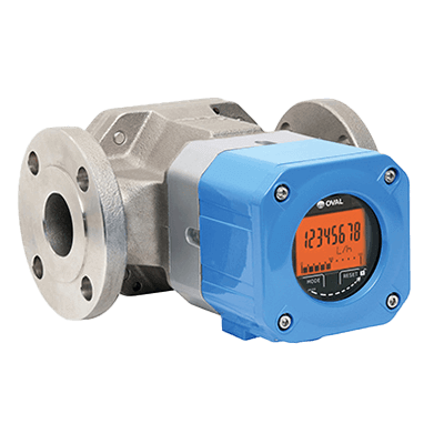
A volumetric flowmeter is a measuring instrument consisting of a flowmeter with a built-in measuring chamber and a rotor (kinematic unit).
This flowmeter is sometimes referred to as a PD meter (Positive Displacement Meter), a term derived from the clearly defined volume of the built-in measuring chamber.
Volumetric flowmeters measure fluid volume based on the number of repetitions of filling and draining of the metering chamber.
Uses of Volumetric Flowmeters
Volumetric flowmeters are well-suited for accurately measuring totalized flow rates.
They find widespread use in industrial instrumentation and other general applications due to their ability to provide high metering accuracy.
Volumetric flowmeter types include rotary pistons, gear, roots, and vane flowmeters, depending on the shape of the rotor. Among these, the rotary piston type is particularly suitable for measuring fuel oil.
The volumetric flowmeter plays a crucial role in flow measurement for transaction verification, especially since it was authorized by the National Tax Administration Agency for assessing taxable quantities of petroleum products.
While the primary measurement targets are fluids, gear and Roots type flowmeters can also measure gases.
Principles of Volumetric Flowmeters
The general principle of volumetric flowmeter operation involves the fluid’s energy actuating the rotor, and the flow rate is calculated based on the rotor’s number of revolutions. One notable feature of this method is that it does not require external energy sources, such as electricity.
Here is an explanation of the operating principle of the Roots type, which is a typical measurement method:
In the roots type flowmeter, a pair of cocoon-shaped rotors is housed in a casing.
These rotors incorporate gears (pilot gears) that mesh with each other and are designed to avoid direct contact between the rotors.
Additionally, a small gap is maintained between the rotor and the inner wall of the casing.
As fluid enters the casing, it pushes the rotor, causing it to rotate outward.
Subsequently, two alternating weighing chambers are formed between the rotor and the inner casing wall (referred to as weighing chambers A and B).
As a result, fluid is discharged downstream through either lightweight chamber A or B.
This sequence of movements mimics the continuous process of measuring one cupful at a time with a measuring cup, and the totalized flow rate can be determined by counting the number of rotor rotations.