What Is a Worm Gear?
Worm Gear is a type of screw gear.
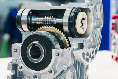
It consists of a worm (worm shaft), which is a threaded toothed shaft, and a worm wheel, which is a helical helical gear with its axis of rotation at 90 degrees to the worm’s axis. Rotation of the worm sends the teeth of the worm wheel, which are meshed with the worm, to rotate.
See Figure 1 for the configuration of Worm Gear.
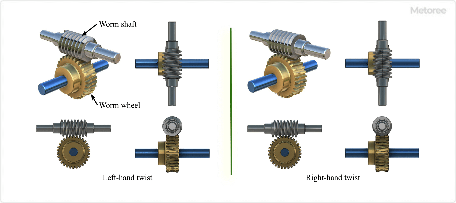
Figure 1. Structure of worm gear
Uses of Worm Gears
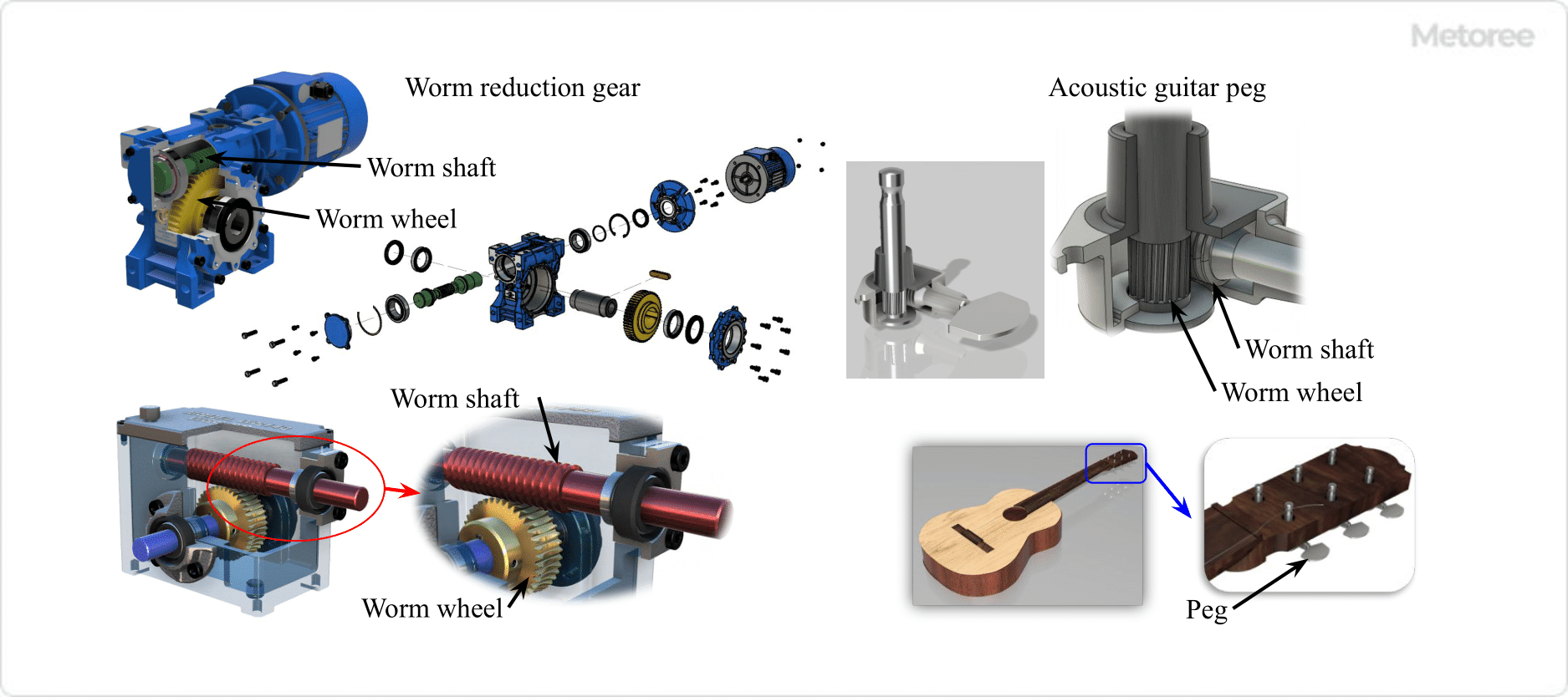
Figure 2. Example of worm gear use
Worm Gears are orthogonal shafts that can transmit power by changing the axial direction by 90 degrees, and can produce a large reduction ratio even when the gears are small. As a result, worm gears are used in a variety of fields and devices, such as conveyor belts in factory equipment, screw jacks, steering systems for automobile steering wheels, wiper drives, pivoting mechanisms for electric fans, material feeders in food and drug manufacturing equipment, music boxes, and stringed musical instrument pegs.
1. String Instrument Pegs (Spools)
A familiar example is the peg around which the strings of a stringed instrument such as a guitar or bass are wound. The peg consists of a worm shaft, which is twisted by hand, and a worm wheel, which winds the strings around it. The self-locking function ensures that the wound strings are held in place without loosening.
2. Worm Reduction Gears
Worm reduction gears are capable of moving large objects with little force and are incorporated into factory equipment and machinery for power transmission. For example, they are used in the drive units of presses and rolling mills, medium- and low-speed elevators, escalator lifting and lowering drives, and conveyor drives.
Worm Gears’ self-locking function may be utilized in the reduction devices of elevators and escalators to serve as a safety device to prevent reverse rotation. In general, worm reduction gears are used to configure equipment in industrial applications. They can provide particularly large reduction ratios, enabling deceleration with small input torques. As a result, reduction gears can be manufactured relatively compactly.
Worm Gears are used in cases where a space-saving, large reduction ratio is required to transmit power with orthogonal input and output shafts, or when a self-locking function is used to transmit power.
Worm Gear Principle
In Worm Gear, when the worm (input shaft side) makes one revolution, the worm wheel (output shaft side) rotates by one tooth. The number of teeth on the worm in this case is called the number of worm teeth, or “one worm. In the case of a worm with two worm teeth, one rotation of the worm rotates the worm wheel by two teeth.
The reduction ratio of Worm Gear can be calculated as follows.
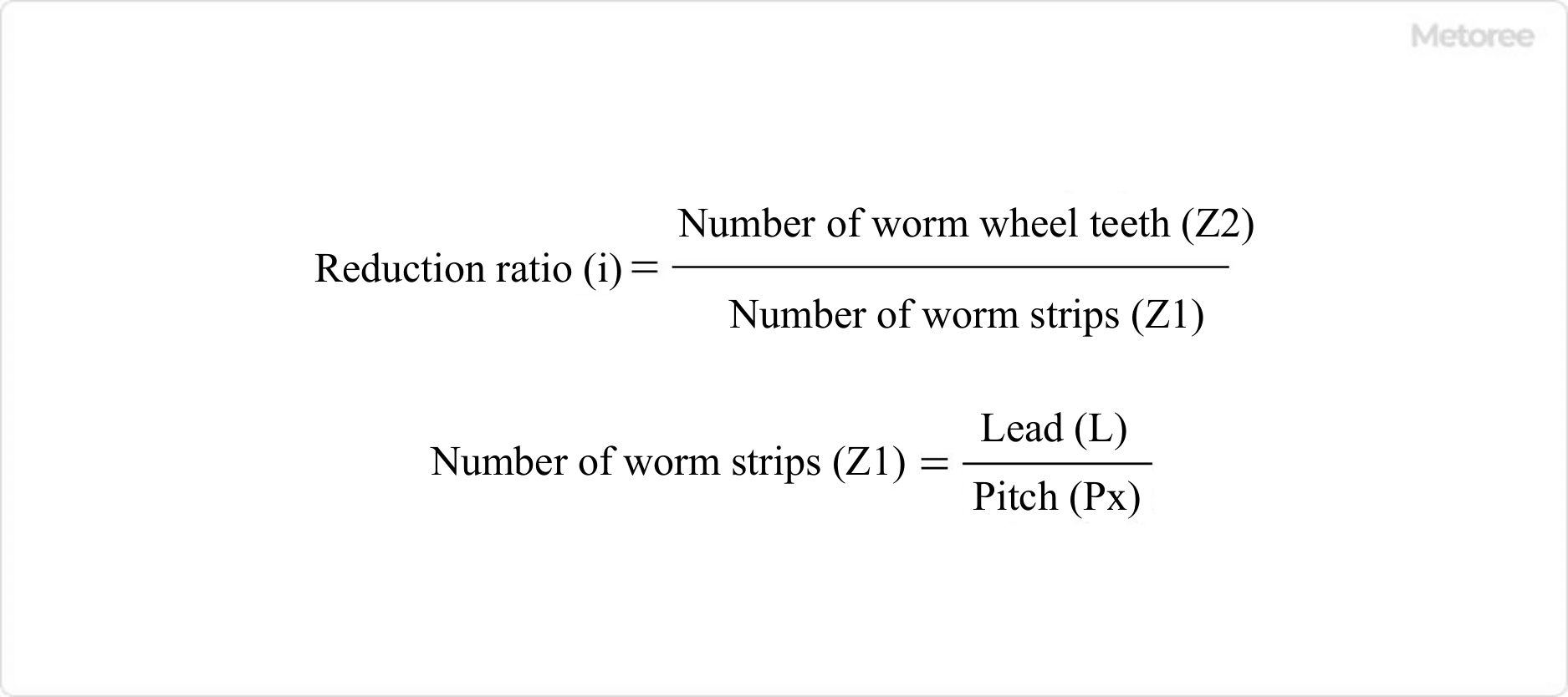
Figure 3. Reduction ratio of worm gear
Worm Gears can rotate in both directions (e.g., clockwise and counterclockwise as viewed from the input shaft side). This can be achieved by selecting the worm torsion direction as left-hand or right-hand. See Figure 4 for Worm Gear torsion direction and shaft rotation direction.
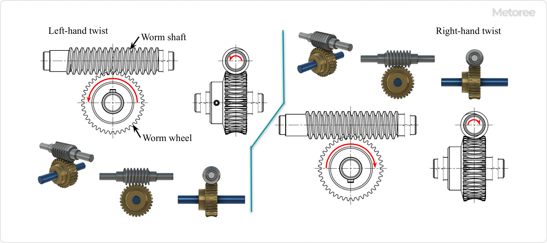
Figure 4. Worm gear torsional direction and shaft rotation direction
Refer to Figure 5 for the worm Gear’s torsional direction and the shape of each part.
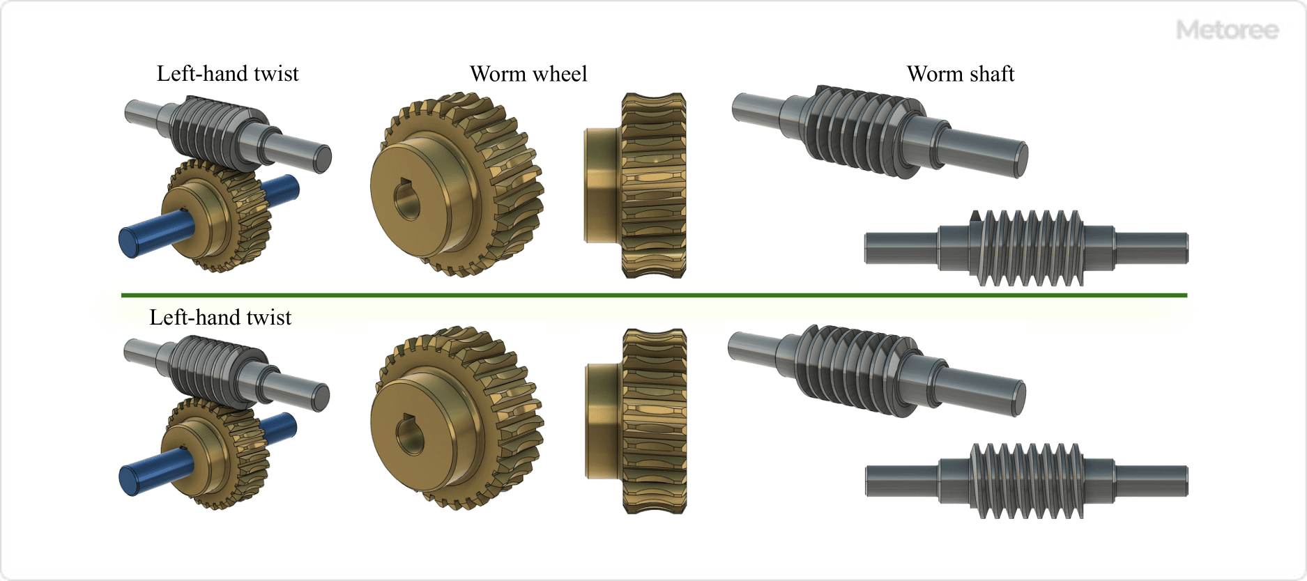
Figure 5. Worm gear torsional direction and shape of each part
Features of Worm Gears
Worm Gears have the following features
- The axial directions of the input and output sides can be orthogonal (but not coaxial).
- Large reduction ratios are possible (e.g., 1/10 to 1/100).
Less backlash (gap or play between gears). This results in better - tooth meshing and less meshing noise.
Large output torque can be obtained from small input torque.
Self-locking phenomenon occurs. - Worm Gear transmits rotation from Worm to Worm Wheel, but conversely cannot transmit rotation from Worm Wheel to Worm.
- This inability to rotate from the output shaft side is called “self-locking.
Therefore, the worm side is always the input shaft side, where the rotating shaft that serves as the drive or power source is mounted.
The worm wheel side is the output shaft side, where the device that transmits power is mounted. However, a separate braking mechanism must be provided to completely prevent reverse rotation. Since pitch error and other factors vary depending on the accuracy of the gear, check the required accuracy and select the appropriate accuracy for the application.
Worm Gears are not suitable for high-precision positioning because of backlash. For high-precision positioning, it may be better to re-select the gear type.