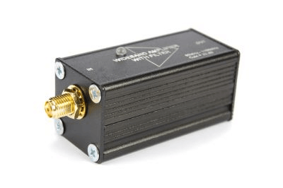
What Is an RF Amplifier?
 The “RF” in RF Amplifier stands for “Radio Frequency” and refers to the high frequency used in mobile wireless communications such as radios and smartphones.
In general amplifiers, the input voltage or current is amplified and output, but in the case of RF amplifiers, instead of this function, DC bias is used to amplify high-frequency power signals by the gain of the amplifier relative to the input power. Therefore, the power for DC bias can be used for amplifying high-frequency power with relatively high efficiency without loss of DC bias power.
It should be noted that the electrical characteristics required for RF amplifiers, i.e., the type of amplifier, differ depending on whether they are used for receiving or transmitting circuits.
RF amplifiers are characterized by their ability to amplify and convert DC power to high-frequency power without loss of DC power, and are considered to be highly efficient RF Amplifiers. The type differs depending on whether it is used for receiving or transmitting circuits.
Uses of RF Amplifiers
RF circuits for communication are divided into blocks for receiving and transmitting, and the type of RF amplifier generally differs depending on whether it is used for receiving or transmitting.
RF amplifiers used on the transmitting side are called Power Amplifiers (PA), which require high amplification. Because of the large amount of power handled, it is important to have low power consumption, i.e., high amplifier efficiency, in order to maintain reliability by suppressing heat generation and battery power consumption. Also, depending on the application, the amplifier itself must have sufficient linearity to prevent signal distortion.
On the other hand, RF amplifiers used for reception are called Low Noise Amplifiers (LNA). They are characterized by low noise (NF) generated by the amplifier itself to prevent the signal from being buried in the noise and to maintain communication quality by increasing the reception sensitivity during communication.
Principle of RF Amplifier
Si MOSFETs, SiGe bipolar transistors, HBTs and HEMTs using compound semiconductors such as GaAs and GaN crystals are used as semiconductor devices for RF amplifiers. It is important to select the optimum semiconductor device according to the maximum output power, gain, efficiency, linearity, and noise figure of the RF amplifier.
Depending on the RF frequency, the frequency response, called the cutoff frequency (fT), may not be sufficient to draw sufficient amplification. Therefore, the stand-alone frequency response determined from the structure of the semiconductor device is a very important factor in constructing an RF amplifier.
The amplifier characteristics are determined by applying the desired DC bias to the amplifier device and optimally setting the input and output load lines of the amplifier. In addition to the fundamental frequency impedance setting, the harmonic impedance setting is also important, and together with the bias, various operating classes (Class A, Class C, Class F, etc.) can be set.
Other Information on RF Amplifiers
RF Amplifier Characteristics
RF Amplifier characteristics include 1 dB compression, gain, and noise figure. In the gain and power curves, 1dB compression is used as a measure of the maximum amount of power output with 1dB of gain suppressed due to amplifier saturation operation.
Since a large output power is required on the transmit side, it is customary to select an amplifier with a large 1 dB compression region and use it up to its upper limit. An RF amplifier can express its frequency response by its amplification, which is the power ratio between input and output, and its performance is judged by its being within a fixed range of frequency The higher the gain, the better.
Higher gain is desirable, but care must be taken as it is a trade-off between power consumption and noise. The noise figure expresses the degree to which the signal-to-noise ratio worsens. When selecting the RF amplifier for the receiving side, choose a small noise figure.