What Is a Servo Motor Reducer?
A servo motor reducer (servo motor gearbox) is a device that reduces the rotational speed of the output shaft of a servo motor by means of gears to obtain torque proportional to the reduction ratio.
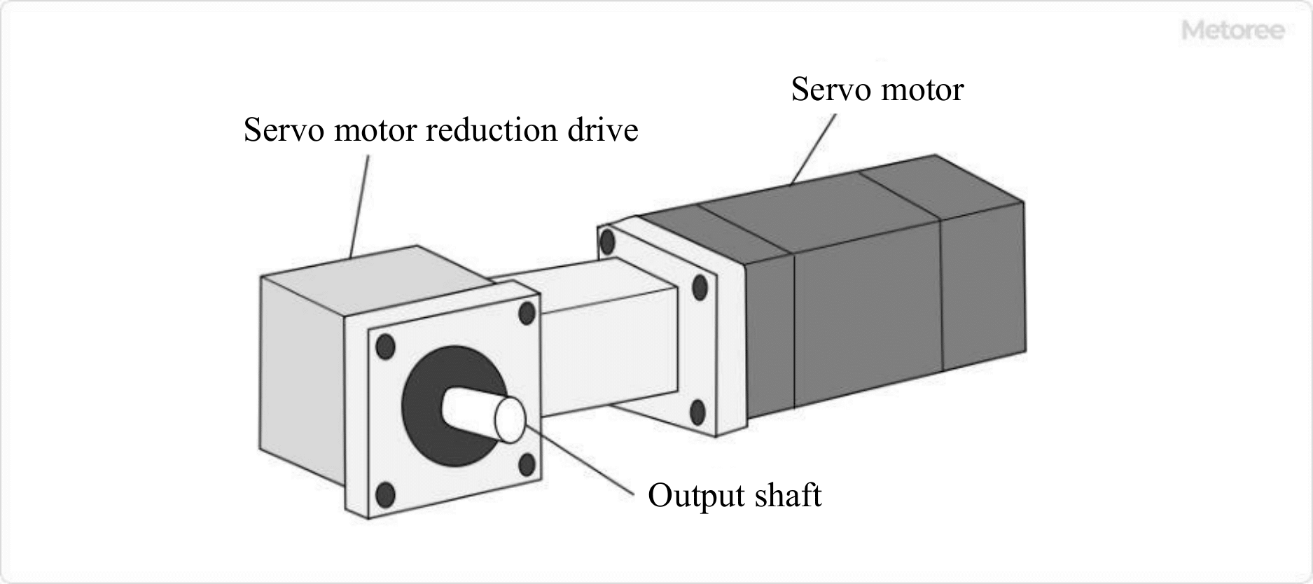
Figure 1. Servo motor reduction drive
Some models have a hollow output shaft that allows cables and other components to pass through.
The greatest advantage of using a servo motor reducer is that it allows a small motor to produce a large amount of torque.
If you try to operate a device with a servomotor alone, you will need a large output servomotor, which will increase the overall weight and size of the device. The use of servo motor reducers, on the other hand, can generate 4 to 100 times as much torque as a servo motor alone. This eliminates the need for large motors, making the equipment smaller and less expensive.
Understanding the type of reducer, its features, and product specifications, and selecting the right gear and reduction ratio for the application are important factors in configuring equipment that uses Servo motor reducers.
A similar concept also exists for products called geared motors.
Uses of Servo Motor Reducers
Servo motor reducers are mainly used in automated devices that run in factories.
Specific specification applications include the following:
- Drive unit of articulated robot
- Wheel drive unit for mobile robots and AGVs
- Press fitting mechanism of press fitting equipment
- Magazine drive mechanism for tool changers in machine tools
- Packaging machinery (bag making machine, pillow packaging machine)
- Turntable drive unit
Principle of Servo Motor Reducers
Servo motor reducers contain gears. The gears change the power obtained from the output shaft of the servomotor as follows.
- Decreases the rotation speed by (1/reduction ratio) of the gear
- Torque is increased in proportion to the reduction ratio
Let’s take the gear below as an example to illustrate.
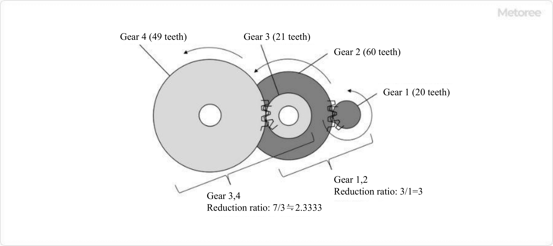
Figure 2. Principle of servo motor reduction drive
Consists of two gears: (1) Gear 1 to Gear 2 (reduction ratio: 3/1=3) and (2) Gear 3 to Gear 4 (reduction ratio: 7/3≒2.33).
The reduction ratio of this gear combination is:
(Reduction ratio of ①) × (Reduction ratio of ②) = 3/1 × 7/3 = 7
The reduction ratio of this gear combination can be calculated as follows.
This servo motor reducer changes the power of the output shaft of the reducer as follows.
- Rotation speed is reduced to 1/7
- Torque increases by a factor of 7 (Note 1)
(Note 1) Strictly speaking, the torque on the output shaft will be smaller than 7 times due to gear friction and other losses. For simplicity, losses are ignored here.
Types of Servo Motor Reducers
Servo motor reducers are broadly classified into two types: orthogonal-axis and parallel-axis.
In orthogonal-axis reducers, the output shaft of the servo motor reducer is orthogonal to the output shaft of the reducer. The gears used in the orthogonal shaft reduction gears are mainly worm gears and hypoid gears. In parallel shaft reduction gears, the output shaft of the servo motor reducer is parallel to the output shaft of the reducer. Gears used in parallel shafts are mainly planetary reduction gears.
The features of each are described below.
1. Worm Gear (Orthogonal Shaft)
It is characterized by high strength, high quietness, and is easy to make the output shaft hollow. it can be combined with motors of about 0.2~15kW, and the reduction ratio range is about 1/10~1/60.
2. Hypoid Gear (Orthogonal Shaft)
Compared to worm gears, they are characterized by high efficiency. They can be combined with motors of about 0.2~11 kW, and the reduction ratio range is about 1/5~1/200.
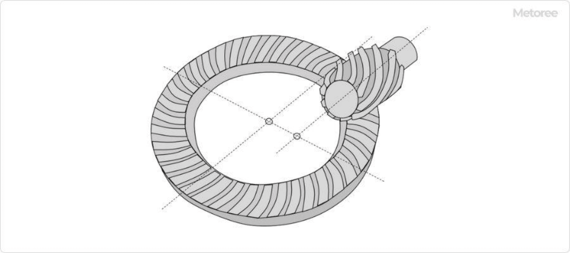
Figure 3. Hypoid gear
3. Planetary Reduction Gear (Parallel Shaft)
It features high efficiency, and the reduction ratio can be increased by increasing the number of stages. 0.2~3kW motors can be combined, and the reduction ratio range is approximately 1/3~1/100.