カテゴリー
category_usa

DC Clamp Meter

What Is a DC Clamp Meter?

A DC clamp meter is an electrical measuring tool specifically designed to measure direct current (DC) without interrupting the circuit. Unlike AC clamp meters or dual-purpose AC/DC clamp meters, DC clamp meters are particularly adept at measuring microcurrents in DC circuits, although they are less common than dual-purpose models.

Clamp meters measure current by encircling a wire with their clamp head, capturing the magnetic field generated by the current and converting it into a readable current value. This method offers a non-intrusive and safe way to measure current flow in a circuit.

Uses of DC Clamp Meter

DC clamp meters are ideal for measuring low-range currents (from 0.1mA to about 100mA), making them suitable for semiconductor and electronic circuit applications. While specialized high-voltage DC clamp meters are rare, dual-purpose AC/DC clamp meters are often used for higher-voltage applications. Their non-intrusive measurement capability makes them safe and convenient for electrical work.

Principle of DC Clamp Meter

DC clamp meters use a magnetic core and a Hall element to detect and measure the magnetic field generated by the current flow in a wire. The core is designed to open for wire insertion and then close during measurement. Hall elements output a voltage proportional to the magnetic field’s density (Hall effect), allowing the accurate measurement of DC currents. However, magnetization of the core can lead to measurement errors, so periodic demagnetization is necessary. The meter’s processing unit calculates the current value based on the Hall element’s output.

How to Use a DC Clamp Meter

1. Clamping Method

To use a DC clamp meter, simply clamp the cable within the meter’s head. Positioning the cable at the center of the head ensures minimal measurement error.

2. Current Direction

The current direction matters when measuring DC. Clamp meters typically have “+” and “-” markings indicating current flow direction, which affects whether the measured value is positive or negative.

3. Leakage Current Measurement

To measure leakage current in a device, pass one of the cables (outgoing or return) through the clamp head. If there’s leakage to the ground, the return current will be less than the outgoing current. Clamp the meter around the ground wire to measure this leakage current, typically a few mA to several tens of mA, which is well within the range of DC clamp meters designed for microcurrent measurements.

カテゴリー
category_usa

Chloroprene Rubber

What Is Chloroprene Rubber?

Chloroprene Rubber

Chloroprene rubber is a synthetic rubber known for its balanced properties, including ozone, oil, and heat resistance. It is used in various applications such as automotive belts, hoses, O-rings, and adhesives. This rubber is characterized by double bonds between carbon atoms in its main chain and the presence of chlorine atoms attached to these carbon atoms, enhancing its oil and chemical resistance.

Commercial chloroprene rubber often has a modified main chain structure, with common types including mercaptan-modified, xanthogen-modified, and sulfur-modified, each chosen based on specific application needs.

Uses of Chloroprene Rubber

Chloroprene rubber’s excellent resistance properties make it a versatile material in the automotive and manufacturing industries. Its applications include belts, hoses, wires, cables, O-rings, and adhesives. It is also soluble in organic solvents, making it useful in adhesive formulations for bonding a wide range of materials.

Principle of Chloroprene Rubber

Chloroprene rubber, made from acetylene or butadiene, has chlorine directly bonded to carbon atoms with double bonds. The chlorine enhances its resistance properties. Chloroprene monomers are typically produced using the butadiene method due to safety considerations. Polymerization of these monomers via radical emulsion polymerization results in chloroprene rubber.

Properties of Chloroprene Rubber

Modified types of chloroprene rubber, such as mercaptan-modified, xanthogen-modified, and sulfur-modified, offer various properties suitable for different applications. While copolymers of chloroprene rubber are less common due to manufacturing complexities, certain types like those with methacrylic acid or 2,3-dichloro-1,3-butadiene have unique properties for specific uses.

カテゴリー
category_usa

Lock Switch

What Is a Lock Switch?

Lock Switch

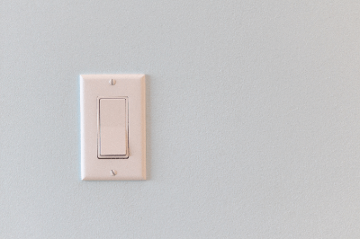
A lock switch, often known as a rocker switch or seesaw switch, toggles on and off by pressing its ends alternately. It’s named for its rocking motion and is characterized by a distinctive “click” sound during operation, providing clear tactile feedback. The switch’s position after use visually indicates the on/off status of the connected device.

Lock switches are available in alternate and momentary types. The alternate type maintains its position after being pressed, while the momentary type returns to its original state once released.

Uses of Lock Switch

Lock switches are widely used in electronic devices for power on/off functions, including in computers, photocopiers, printers, household appliances, and industrial machinery. They also find applications in residential lighting systems. Available in various shapes, colors, and sizes, they can handle currents exceeding 100 amperes, making them suitable for diverse applications.

Principle of Lock Switch

A lock switch consists of an operating button, bow spring, case, cover, and contact terminals.

1. Operating Button

The operating button, manipulated to switch between on and off, is connected to the internal bow spring. It varies in shape and may indicate the on/off state.

2. Bow Spring

The bow-shaped spring facilitates the switch’s movement. When turned on, it brings the movable contact close to the fixed contact, ensuring stable contact. In the off position, it separates the contacts, preventing current flow and reducing contact erosion.

3. Built-in Case/Cover

The case or cover, usually made of resin, encloses the internal components, protecting them from external elements.

4. Contact Terminals

These terminals connect the switch to external circuits. In multiple switches, one terminal may serve as a distribution point, necessitating careful verification of the internal circuitry to avoid shorts.

Types of Lock Switch

1. Alternate Type

This type remains pressed until the opposite side is pressed, suitable for applications like power buttons or residential lighting switches.

2. Momentary Type

This type only connects contacts while pressed, automatically returning to off when released. It’s used in scenarios where continuous switch operation is not desired, like in electric kettles or drills.

Both momentary and alternate types of lock switches are selected based on their specific application requirements.

カテゴリー
category_usa

Water Meter

What Is a Water Meter?

Water Meter

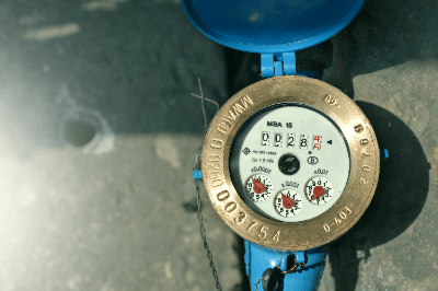
A water meter is an instrument used to measure and record water consumption, typically in municipal water supply systems. It is essential for calculating tap water usage fees and is regulated under the Measurement Act. Water meters must be produced by manufacturers authorized as specific measuring instrument production sites, and they have set expiration dates after which they cannot be used for fee determination.

Authorized production sites can be verified on the Ministry of Economy, Trade and Industry’s website.

Uses of Water Meters

Water meters are commonly used in residential and commercial settings. In residences, they are installed in easily accessible areas like entrances or basements. Meter readings, conducted monthly or more frequently by local authorities, are used to calculate water bills. For corporations, water meters are installed on both supply and intake lines for accurate billing and usage tracking.

Non-certified water meters can be used for non-billing purposes, such as in factory line management and other applications where no charges are involved.

Principle of Water Meters

Water meters are a type of flow meter.

The impeller-type flow meter is widely used for measuring water flow. In this meter, water flow rotates an impeller, with the rotation rate indicating the flow rate. This direct measurement method requires no external power and is highly accurate for tap water, which typically contains minimal impurities.

Electromagnetic flow meters are another option, particularly suitable for tap water due to its conductivity. They work by applying an electromagnetic force perpendicular to the flow and measuring the resulting electromotive force. While they require external power, many models include batteries that last for the meter’s specified lifespan.

カテゴリー
category_usa

Electronic Micrometer

What Is an Electronic Micrometer?

Electronic Micrometer

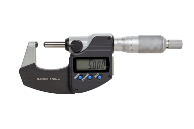
An electronic micrometer, also known as an electrical comparator, is a precision instrument that uses a contact-type measuring probe to convert small physical displacements into electrical signals for measurement. This device measures variations in electrical resistance, electrostatic capacitance, and electromagnetic induction resulting from probe displacement.

Uses of Electronic Micrometers

Electronic micrometers are used in precision engineering for measuring dimensions such as height, depth, and thickness. They are particularly useful for measuring eccentricity in rotating bodies, oscillation, and vibration in parts, and are prevalent in manufacturing where high accuracy is required. Most models can measure with a precision of up to 1µm.

Principle of Electronic Micrometers

Electronic micrometers function by detecting displacements using a contact probe connected to a converter that translates these physical changes into electrical signals. Differential transformers are commonly used in these devices for conversion.

1. Plunger Type

In the plunger type, the probe’s displacement is directly linked to a differential transformer. The transformer, with a movable iron core, responds to position changes, generating voltage differences that are amplified and measured.

2. Lever Type

The lever type uses an arm connected to a measuring probe, where the rotation of the arm moves the iron core of the transformer. This displacement is proportional to the probe movement, making it suitable for applications like measuring bearing deflection.

Characteristics of Electronic Micrometers

1. High Magnification

Electronic micrometers offer high magnification readings, typically ranging from 0.2 to 1µm. They provide flexible options with multiple magnification levels, allowing for varied measurement ranges.

2. Compact and Lightweight

Their compact and lightweight design makes them suitable for field use, and they can be operated remotely.

3. High Performance

These micrometers are known for their stability, precision, and ease of use.

Challenges of Electronic Micrometers

1. Measurement Stability
Contamination between the probe and the measured object can cause errors. Soft materials like rubber or plastic may deform under the probe, affecting accuracy. Additionally, variations in temperature between the micrometer and the object can lead to measurement errors, necessitating temperature control.

Regular maintenance and calibration using block gauges are essential for maintaining accuracy.

2. Reduction of Labor and Cost
Ensuring the zero point before measurement is crucial, and the time-consuming nature of contact measurements can vary based on operator skill. The use of different ratchet mechanisms during measurement can impact efficiency. Additionally, manual recording of measurements can be labor-intensive, highlighting the advantage of micrometers with digital output capabilities for efficiency.

カテゴリー
category_usa

Panel Cabinet

What Is a Panel Cabinet?

Panel Cabinet

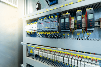
A panel cabinet is a protective enclosure used in industrial control panels, housing equipment such as electromagnetic contactors, and circuit breakers. These cabinets safeguard the electrical circuits and devices inside from environmental elements like water, dust, and sunlight, and also prevent electric shock by restricting access to hazardous areas.

Uses of Panel Cabinets

Panel cabinets are widely used in various settings where industrial control equipment is needed. They are commonly found in commercial facilities, typically installed in less accessible areas to manage power supply and control. Signal control cabinets under electric poles, as well as cabinets in schools and station buildings, are also examples. Despite their crucial role, they are often placed discreetly out of plain sight.

Principle of Panel Cabinets

Panel cabinets are primarily made from metal for durability, cost-efficiency, and workability. In environments prone to corrosion, such as coastal areas, materials like stainless steel or plastic are used. They are frequently painted to blend into their surroundings, with customizable color options available. For enhanced corrosion protection, coatings resistant to salt and acid may be applied.

The cabinets usually feature lockable handles to prevent unauthorized access and reduce injury risks. Internally, they contain plates or substrates for organizing control equipment, mounted onto the cabinet’s back.

When installed outdoors, panel cabinets are designed with a roof for water drainage and are structured to prevent dust and water ingress, ensuring a protection rating of IP44 or higher.

カテゴリー
category_usa

Object Detection Sensor

What Is an Object Detection Sensor?

Object Detection Sensor

An object detection sensor is a device used to confirm the presence or absence of an object at a specific location. Detection methods include optical, mechanical contact, and ultrasound techniques. Optical sensors, such as photoelectric and fiber sensors, are the most commonly used, offering various types like through-beam, retro-reflective, diffuse-reflective, and narrow-angle reflective for different applications.

Uses of Object Detection Sensors

These sensors are widely used in Factory Automation (FA) machinery and robots, particularly for detecting the presence of parts in feeders or confirming the positioning of components. They are also used for monitoring actions like door opening and closing, extending beyond mere object presence detection.

Principle of Object Detection Sensors

Selection of the appropriate sensor type depends on the nature of the objects to be detected. For instance, photoelectric sensors vary in type: through-beam sensors are ideal for non-light-transmitting objects, while reflective sensors are used for objects that reflect light. Retro-reflective sensors are particularly effective for transparent objects, using a reflective plate to enhance detection accuracy.

Fiber sensors, requiring a separate amplifier, are well-suited for tight spaces. Laser sensors, known for their linearity and use of visible light lasers, excel in identifying detection positions and detecting narrow gaps. In situations where color differentiation is required, color sensors can be employed for specific object detection.

カテゴリー
category_usa

Auto Switch

What Is an Auto Switch?

An auto switch, also known as an auto-detection switch, is a position-detection device designed to identify magnets in machinery such as air and hydraulic cylinders. Unlike infrared sensors, which can degrade over time, auto switches use permanent magnets for reliable, long-term detection. They are typically easy to install on cylinders, making them user-friendly.

Uses of Auto Switches

Auto switches are primarily used with cylinders, incorporating magnets at both ends to monitor their positions. They are essential in systems like PLCs for detecting the extension and retraction of cylinders, aiding in operations like confirming retraction, extension, and free movement detection.

Principle of Auto Switches

There are two main types of auto switches: contact and non-contact. contact auto switches use mechanical reed switches that bend near magnets to create an electrical connection and signal output. Although they have a shorter lifespan due to moving parts, they are straightforward in terms of electrical handling.

Non-contact auto switches use a magnetic detection element and electronic circuitry for signal generation and amplification, offering a longer lifespan as they lack mechanical contacts.

Auto switches operate on magnetic forces, allowing them to detect and signal at any position along a cylinder with multiple adjustment stages. The sensor gradually detects the magnet as it approaches and outputs a signal when a specific threshold is surpassed. For multi-stage adjustments, careful tuning of the installation position is necessary while verifying the operation.

カテゴリー
category_usa

Stop Bolt

What Is a Stop Bolt?

A stop bolt, also known as a stopper bolt, is utilized in machining operations such as metal processing to position and secure workpieces. To prevent loosening, it is often paired with a locking nut. Considering its exposure to impacts, it is designed with both strength and impact resistance in mind, achieved through material selection and specific mechanisms.

Uses of Stop Bolts

Stop bolts are employed in various machining contexts as mechanical stoppers and in linear stopper assemblies for positioning workpieces. They are also used in seismic equipment to secure bases. In some specialized setups, stop bolts are integrated with touch switches, serving dual roles as both stoppers and switch activators, thereby enhancing efficiency and durability against collisions.

Principle of Stop Bolts

The design of stop bolts varies according to their use. When functioning as stoppers, they feature robust heads, often quench-hardened or flat-shaped for better impact resistance. To minimize impact, some bolts have heads with resin protection like urethane or include shock absorbers.

For positional adjustments, stop bolts are made from durable materials like SUS304 steel or undergo heat treatment for increased hardness. Fine threads are also common for precise adjustments.

In configurations with touch switches, where impacts are expected, stop bolts are made from materials with sufficient strength and may also be designed for water and oil resistance, depending on the equipment’s specific requirements.

カテゴリー
category_usa

Roller Conveyor

What Is a Roller Conveyor?

Roller Conveyor

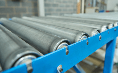
A roller conveyor, particularly a free roller conveyor, is a conveyor component that lacks a motor or other driving source. Commonly known as “free rollers,” these rollers are made from materials like iron, aluminum, or plastic and are used not only in free roller conveyors but also as guide rollers in belt conveyors and in discharge devices.

Free roller conveyors operate using human power or gravity, thanks to their hollow, lightweight design that allows for easy rotation.

Uses of Roller Conveyors

Free roller conveyors are used in warehouses and factories for moving goods. They can be manually pushed, used on inclines for gravity-driven movement, or powered by residual energy from discharge devices. Their lightweight and easily rotatable design enables the conveyance of goods with minimal force.

When part of a free roller conveyor, these rollers are attached to the conveyor frame with the shaft inserted into the frame and secured with snap pins or similar fasteners.

Features of Roller Conveyors

Roller conveyors consist of shaft and roll parts, both hollow to reduce weight. The shaft has holes at both ends for attaching snap pins, and press bearings are built into the roll ends to support rotation.

Material choices vary: iron rollers are robust for heavy loads but not suitable for corrosive environments; aluminum or plastic rollers are preferred in hygienic settings.

While their lightweight and rotational ease are advantageous, they can lead to issues like “bumper-to-bumper” accidents on inclines or risks of goods slipping off or falling if the installation surface is not level.