カテゴリー
category_usa

Honing Machine

What Is a Honing Machine?

Honing Machines

A honing machine is one of the machines used for surface finishing. The machine rotates while crushing the inner surface of a cylindrical workpiece with multiple grinding wheels attached in the shape of sticks to finish the inner surface.

Since it is not possible to cut a large number of pieces at once, honing machines are generally used for final finishing after cylindrical cutting with boring machines or other machines.

Although honing machines are similar to internal grinding machines, they are capable of machining more precise hole accuracy, roundness, and higher surface roughness.

Uses of Honing Machines

Honing machines are often used for machining the internal surfaces of engine cylinders, which require extremely high precision in order to achieve the final finish on cylindrical workpieces.

The surface roughness is almost mirror finish, but if you look closely, you can see small scratches in the form of crossed lines, which adhere to the engine oil and keep the oil film to protect the cylinder from friction with the piston, so it is ideal for machining engine cylinders that constantly circulate high pressure oil.

Principle of Honing Machines

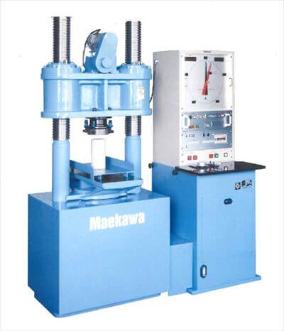
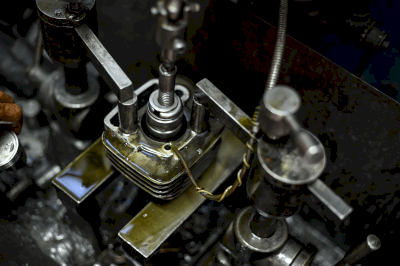
Most honing machines are vertical machines, and the bore is machined by the up-and-down motion of a grinding wheel attached to the stick-shaped tip.

Other types of honing machines include the parallel flat honing machine, which sandwiches the workpiece between two disk-shaped grinding wheels and uses a reciprocating motion to align multiple workpieces to a uniform height; the CNC multi-axis honing machine, which performs the entire process automatically, eliminating the need to use separate grinding wheels for intermediate and final finishing operations; and the honing machine with a water and abrasive grain mixture sprayed onto the workpiece. Liquid honing, in which a mixture of water and abrasive grains is sprayed onto the workpiece to create a matte finish on the surface, and other types of honing.

Both of these processes do not apply heat or load to the workpiece as in the cutting process, and they do not affect the accuracy of heat-sensitive workpieces. However, the honing process is based on the shape created by the grinding process prior to honing, so the quality of the previous process is important to achieve high accuracy.

In addition, honing cannot exceed the outside diameter of the stick on which the grinding wheels are mounted, because the multiple grinding wheels are all attached to each other in close contact. Therefore, it is necessary to prepare separate sticks for the inner diameter of each workpiece and separate grinding wheels to be attached to the sticks, which has the disadvantage of being very costly.

Honing Process Cross Hatch

A fine mesh of scratches created by honing is called a cross hatch.

Cross-hatches are formed gradually by the repetitive back-and-forth motion of a rotating horn that creates a fine mesh of scratches at different angles when moving downward and upward.

First, a coarse grindstone is used in roughing to create a large-angle mesh at a relatively slow rotation speed, followed by finishing with a fine grindstone at a higher rotation speed to create small-angle scratches, and finally cross-hatching is formed with an angle of about 20° to 60°.

By creating cross hatches in this way, oil can enter the grooves of the cross hatches where metals slide against each other, preventing the oil film from running out.

Examples of this process include engine parts such as cylinders, rocker arms, and connecting rods.

Difference Between Honing and Polishing

Honing and polishing (internal grinding) can both be used for hole drilling with high precision as finishing processes, but the machining methods are different.

Honing involves pressing multiple cylindrically mounted grinding wheels together in a reciprocating motion, whereas internal grinding involves placing only one point of the grinding wheel on the workpiece and rotating the workpiece and grinding wheel together.

Honing can produce a higher roundness and surface roughness than internal grinding, but it has the disadvantage that it cannot be corrected because it follows the hole drilled in the previous process, whereas internal grinding can be corrected to some extent and is determined by the accuracy of the centering process.

In addition, cross hatches can only be produced by honing, which cannot be done with internal grinding.

Incidentally, one of the hole finishing tools often used on milling machines is a reamer, which is also used for hole finishing, but has the disadvantage that it is more difficult to handle hardened, high-hardness steel than grinding.

カテゴリー
category_usa

Reference IC

What Is a Reference IC?

A reference IC is an electronic component that outputs a reference voltage for operating an electronic circuit. Such electronic circuits are also sometimes called reference circuits or reference voltage sources.

The performance of a reference IC includes the initial accuracy of the output reference voltage, stability against fluctuations in supply voltage (called line regulation), stability against load regulation, stability against changes in ambient temperature (called temperature drift), and stability against long-term use (called long-term drift). The reference IC is required to maintain stable voltage output with high accuracy on the order of ppm (0.0001%).

Uses of Reference ICs

Reference ICs are used in a variety of electronic circuits that require a reference voltage. In power supply control circuits, the output voltage is compared to a reference voltage to maintain a constant output voltage; in AD and DA converters, the input voltage is compared to a reference voltage to convert it to an appropriate output. In a voltage detector, the detection decision is made by comparison with a reference voltage.

Therefore, the performance of these electronic circuits is affected by the performance of the reference IC. Especially in the fields of science, medicine, automotive, military, aviation, and space, reference ICs with high accuracy are required.

Principle of Reference ICs

There are two types of reference IC configurations: shunt type and series type.

The shunt type consists of two terminals, the reference output, and ground, and is controlled to maintain a constant voltage drop regardless of the current flowing between the two terminals. When used, the IC is connected in parallel to the load, and an external resistor is connected between the power supply and the reference output. The current flowing through the IC varies with the supply voltage and load, but the voltage at the reference output is kept constant by the control of the IC.

The series type consists of three pins: power supply input, reference output, and ground, and when used, the IC is connected in series between the power supply and the load. The reference output is controlled to maintain a constant voltage by varying the internal resistance of the IC in response to variations in supply voltage or load.

The most commonly used method today is the bandgap reference. By matching a voltage with a positive temperature coefficient with a voltage with a negative temperature coefficient, a stable voltage output can be maintained over temperature variations.

When using a reference IC, it is necessary to properly select one that provides the performance required for the application, including not only accuracy and stability, but also start-up settling time and noise characteristics.

カテゴリー
category_usa

Laser Doppler Speedometer

What Is a Laser Doppler Speedometer?

Laser Doppler Speedometer is a device that measures the velocity of an object using the Doppler effect of laser light. A laser beam is shined onto the object to be measured, and the velocity of the moving or rotating object is measured. Advantages of Laser Doppler Speedometers include high resolution and the ability to detect the direction of rotation, such as reverse rotation.

Laser Doppler Speedometers are also called Laser Doppler Velocimeters when the object being measured is a gas or liquid. Laser Doppler Speedometers measure flow velocity by shining a laser beam on tiny droplets of water or other substances mixed into the gas or fluid flow.

Uses of Laser Doppler Speedometers

Laser Doppler Speedometers are used to measure the speed of moving objects such as belts, and rotating objects such as rolls, motors, and gears. They are also used to detect the opening and closing of elevators. Objects to be measured include paper, building materials, aluminum foil, cables, cheese (food), steel plates, and many others.

Applications of laser Doppler anemometers range from basic fluid dynamics research to industrial measurements of flow around objects such as aircraft, ships, and automobiles. Examples include wind experiments to analyze the aerodynamic characteristics of vehicles and aircraft, and the analysis of the flow of fuel, air mixtures, and exhaust gases in engines.

Principle of Laser Doppler Speedometers

Both Laser Doppler Speedometers and velocimeters utilize the Doppler effect. The Doppler effect is a phenomenon in which the frequency of a wave is shifted when the source of the wave, such as sound or light, and the device that observes or detects the wave, or both, are moving. A familiar example in our daily lives is the phenomenon in which the sirens of ambulances and fire trucks are heard with a sudden change in sound when they pass in front of our eyes.

The principle of Laser Doppler Speedometer is that when light is irradiated onto a moving object, the frequency of the reflected light is shifted, and this reflected light is detected and used to determine the speed of the object. Since the shifted frequency is smaller than the light and difficult to detect, the original light source is superimposed on the reflected light.

Features of Laser Doppler Speedometers

Other devices for measuring the velocity of fluids include pitot-static pressure tubes and hot-wire anemometers. Compared to these devices, Laser Doppler Speedometers are superior because they do not require calibration, can make non-contact measurements, and can also measure reverse flow.

Other Information on Laser Doppler Speedometers

Characteristics of Laser Light

Laser light has some advantageous features for detecting the Doppler effect. Laser is an acronym for Light Amplification by Stimulated Emission of Radiation. Translated into Japanese, it stands for Light Amplification by Stimulated Emission of Radiation. Laser light has four characteristics not found in ordinary light such as sunlight.

First, it is highly directional. High directivity means that light travels straight in one direction.

Second, it has good coherence. Coherence means that the phases of light are regularly aligned.

The third characteristic is that the wavelength range is very narrow and monochromatic light can be obtained. Finally, it has excellent convergence. Good convergence means that it is easy to focus light to a single point using a lens. When we collect sunlight with an insect-eye lens, paper and other objects burn, but because sunlight has a variety of wavelengths, not all the light is actually concentrated at a single point, even when we think we have focused the light. This is because there is a focusing error called aberration. However, laser light has excellent convergence properties that make it easy to focus light to a single point using a lens.

Measuring Gases and Fluids With Laser Doppler Speedometers

Laser Doppler Speedometers that measure the velocity of gases and liquids require the inclusion of tiny tracer particles such as water droplets, silicone oil, or titanium dioxide in the flow. To measure the velocity of the flow, a laser beam is shone onto these tracer particles, and the scattered light emitted by the particles is detected to determine the velocity of the tracer particles. Therefore, it is important that the tracer particles follow the flow sufficiently.

カテゴリー
category_usa

Rail Terminal Block

What Is a Rail Terminal Block?

A rail terminal block is a terminal block that can be mounted on a rail.

In most cases, rail refers to DIN rails, which are widely used both domestically and internationally. Using rail terminal blocks, many wires can be aligned and grouped together. Having all the wiring in one place makes it easier to organize and manage the wiring. Also, when additional wiring or changes are needed, simply adding new wiring to the terminals on the rail simplifies maintenance work.

Note that rail terminal blocks use screws or spring-loaded clamps to securely connect the wiring. This prevents wiring from becoming loose or causing contact failures, thereby improving reliability. Stable contact is especially important for use in environments subject to vibration and shock.

However, it is important to select the appropriate wiring capacity to be connected to rail terminal blocks according to the current and voltage to be used. If excessive current or voltage is applied, overheating or wiring failure may occur.

Uses of Rail Terminal Blocks

Rail terminal blocks are widely used components in industry. In particular, they are used to electrically connect the external and internal wiring of control panels.

They play a very important role in industrial control systems. Industrial machines and controls require wiring connections for power supply and signal transmission. Rail terminal blocks efficiently organize these wires, distribute signals and power, and make connections.

Power distribution and circuit connections are also required in distribution panels. Rail terminal blocks are used to connect circuits and protective devices for distributing power from the power supplier. This allows wiring in the switchboard to be organized and facilitates maintenance work.

Other applications include automobiles and railroads. They are used in vehicle control circuits and navigation system circuits, where connection points can be organized.

Principle of Rail Terminal Blocks

Rail terminal blocks are basically used at the bottom or side of the control cabinet. This is because control panel external wiring is often routed to the bottom or side of the control panel.

Control panel external wiring uses cables with a hard outer jacket, such as CV cables and CVV cables. These cables are strong against external shocks, but not flexible. When used for wiring inside the panel, they are difficult to handle.

Therefore, cables without hard outer sheaths, such as WL1 and IV, are used for wiring inside the panel. These cables have high flexibility and are best suited for wiring in confined spaces such as inside a panel. Rail terminal blocks are used to electrically connect these different types of cables.

Since they are mounted on a DIN rail, the size of the terminal block that can be installed is limited by the strength of the DIN rail. Fixed terminal blocks are often used for thicker wiring.

Most rail terminal blocks are used for control wiring terminal blocks with a thin wire core, but they can also be used for power wiring with a body cross-sectional area of about 100 mm2.

Types of Rail Terminal Blocks

There are various types of rail terminal blocks, depending on the connection method. The following are examples of rail terminal blocks:

1. Screw Type

These terminal blocks use screws to securely tighten the wiring. They are highly reliable and provide a strong connection. They are inexpensive and widely used.

2. Screw-Up Type

Like the screw type, this terminal block is tightened with screws, but the wiring is pulled up during tightening. This facilitates insertion and removal of wiring. Screw-up terminal blocks are useful when wires are frequently added or replaced.

3. Push-Fastening Type

This is a terminal block in which the wiring is secured directly by tightening screws. Wires are inserted into the clamp of the terminal block and connected by tightening the screws. No terminal treatment is required, and wiring can be connected quickly and easily.

4. Push-In Type

This terminal block allows connection to be completed simply by pushing the wiring into the clamp by hand. Simply inserting the wiring into the clamp of the terminal block automatically closes the clamp to make a secure connection.

Quick and easy wiring connections can be made, improving work efficiency. Many products remove wiring by pressing a release button.

カテゴリー
category_usa

Rotary Stocker

What Is a Rotary Stocker?

Rotary Stockers

Rotary stockers are circulating rotary shelves that use the ceiling space to store large quantities of parts and products.

They help to save space by making effective use of the height direction, and make it easier to organize a warehouse.

You can choose from a variety of types with one to four take-out ports, single-sided or double-sided take-out, and more. When considering installation, it is important to select the right one for the application, taking into account the environment of the facility where it will be installed and the amount of items to be stored.

Uses of Rotary Stockers

Rotary stockers are used to store and manage assembly parts, processing jigs, and various tooling at manufacturing sites.

Because it is necessary to store all kinds of parts, jigs, and tools in a warehouse at a manufacturing site, the environment is inevitably prone to a large number of items being placed in a disorganized manner.

By introducing a rotary stocker, the time and effort required to move and reload items when taking them out can be reduced, thereby improving work efficiency.

Principle of Rotary Stockers

Inside the rotary stocker, shelves are stacked vertically, each connected to the other in a circle.

The shelves are rotated by entering the desired shelf number on the operation panel from the retrieval slot, and the retrieved shelf is brought to the retrieval slot.

Rotary stockers vary in height and maximum loading weight depending on the type. Shelf types can be selected from standard, partitioned, and multi-tier types.

In addition, a LAN connection can be used to centrally manage multiple stockers with a single PC.

Using these features to keep items in the warehouse organized is very important in terms of inventory management.

At various manufacturing sites, there are a large number of inventory items that are placed in disarray in the warehouse, making it difficult to know where they are and resulting in losses. This means that if inventory items are properly stored and managed, losses can be reduced and profit margins can be increased.

Rotary stockers are a useful device not only for keeping the warehouse organized, but also for inventory control.

カテゴリー
category_usa

Compressed Air Gun

What Is a Compressed Air Gun?

A compressed air gun is a type of non-lethal gun that uses compressor air as its power source to blow, suck, and transport materials.

There are two types of air guns: a hand-held type, which is mainly handled by the user’s hand, and a type that is attached to a specific machine or tool for work.

Since the inside of a compressed air gun is basically hollow and free from obstructions caused by other parts, it is safe to work with because no objects can get stuck inside it during work.

Uses of Compressed Air Guns

The compressed air gun is used in a variety of manufacturing facilities.

The blow-off function can be used to clean the work site by blowing off fine dust, etc. The air pressure generated by the blow-off can also be used for cooling and drying.

Air-blast type machines are also available for spraying abrasive materials, paints, and liquids, and for surface treatment such as rust removal and descaling.

With the suction function, liquids and powders can be suctioned and collected for cleaning.

Principle of Compressed Air Guns

The basic structure of a compressed air gun is very simple, consisting of an outlet, an intake port, and a compressor to compress air.

When the compressed air gun is used for blowing out, compressed air is sent from the compressor to the air outlet, and when outside air flows into the intake port, high pressure air is blown out from the outlet port, allowing work to be performed.

When using the compressor for suction, the compressed air gun’s outlet and inlet ports are reversed and the same operation is performed to suck in the target object from the inlet port.

To ensure safety, a hose or dust collection bag must be attached to the compressed air gun’s outlet.

Furthermore, if a hose or tube is connected to both the outlet and inlet ports, it can be used as a transport gun.

There is also a spiral jet method that can efficiently blow a large volume of air, allowing you to choose a product with the functions that best suit your application and site.

カテゴリー
category_usa

Compression Terminal Lug

What Is a Compression Terminal Lug?

Compression Terminal Lugs

A compression terminal lug is a terminal lug attached to the end of a wire using a special tool, and is used to electrically connect a wire to a terminal block, etc 

Crimp terminals are similar to compression terminal lugs. Both are used because they can connect wire to terminal block without soldering, thus eliminating the need for soldering skills, and also because they are relatively easy to remove compared to soldering.

Compression terminal lugs come in a variety of shapes and sizes, depending on the thickness of the wire to be connected and the terminal block to which they are connected.

Uses for Compression Terminal Lugs

Compression terminals, like crimp terminals, are used to secure wires to terminal lugs or to firmly connect wires to each other. In both cases, they are used to ensure that the wires are securely joined so that they will not come loose.

Terminals are connected using a tool called a compression terminal lug. If the wrong tool is used, the proper compression force will not be applied and the compression terminal lug and wire will only be imperfectly connected.

Note that an incomplete connection may result in the wire disconnecting due to an unforeseen accident such as the wire being pulled.

Principle of Compression Terminal Lugs

In the case of crimp terminals, a part of the vinyl coating is removed from the tip of the wire, which is then threaded through a hole provided in the crimp terminal, and connected to the wire by applying force to one point on the crimp terminal where the wire is inserted using a special metal fitting.

On the other hand, in the case of compression terminal lugs, the tip of the wire, which has been stripped of its coating, is inserted into the hole provided in the compression terminal lug, but force is applied not to a single point of the compression terminal lug in which the wire is inserted, but to the entire wire insertion area to connect the two.

Therefore, the compression terminal lug has a stronger bonding force between the wire and the terminal lug than the crimp terminal lug.

Unlike joining wires by heating, such as soldering or welding, joining wires by compression does not affect the environment. Furthermore, mechanical bonding is resistant to deterioration and is stronger than bonding with insulation tape or other external factors such as wire tension.

When a wire is compressed, the sheath must be properly stripped. If the portion of the wire where the sheath is stripped is short compared to the compressed portion, the compression will be incomplete, and the wire may come loose. Conversely, if too much of the sheath is stripped off, it may cause leakage or fire.

カテゴリー
category_usa

Flexible Terminal

What Is a Flexible Terminal?

A flexible terminal is a terminal for electrical supply that can be bent freely. They are a type of component used to supply electricity.

Flexible terminals can absorb thermal expansion, rapid contraction, and vibration. Unlike cables, they do not have an organic coating and can handle high currents. Due to their high flexibility, they are widely used in power generation and transformation, driving parts, etc. On the other hand, the charging section can be peeled off. Also, since the live part is exposed, it is necessary to take measures to prevent unauthorized persons from easily approaching it.

Uses of Flexible Terminals

Flexible terminals are used in a variety of industries.

For example, they are used in cranes and train pantographs to connect the electron collector to the cable terminal, ensuring both pantograph expansion and contraction, as well as a stable power supply.

They are also used for the connection of thyristors for electrolysis and for the pulling in of power receiving and transforming equipment, taking advantage of their ability to carry large currents. When bus bars are used as high-current conduits, flexible terminals are installed in the midsection to absorb elongation.

Principle of Flexible Terminals

Flexible terminals are divided into a terminal section and a flat braided section.

The terminal part consists of a bus bar with a hole in it. Bus bars are usually made of copper. The connection to the cable or other bus bars is made by fastening a bolt or screw through the hole. However, if the fastening surface is uneven, contact resistance will be high. In such cases, the fastening part will generate heat when a large current is applied, causing burnout or power loss. Therefore, the fastening surfaces are plated with solder, tin, silver, etc. to reduce contact resistance. This plating also serves to prevent corrosion.

The flat braided part is an important part that gives flexible terminals flexibility. The structure consists of several hundred strands of wires thinner than 1 mm2 in diameter, bundled and braided together. The strands are braided together in the same way as in clothing or carpets, making it both strong and flexible, and there is no need to worry about the strands breaking.

As with cables, the allowable current increases in proportion to the thickness of the conductor. The higher the allowable current, the heavier and larger both parts become.

カテゴリー
category_usa

Board-To-Wire Connector

What Is a Wire-To-Board Connector?

A wire-to-board connector, also called a board-to-board connector, is a component used to electrically couple circuits on two printed circuit boards.

Board-to-wire connectors are mounted directly on both printed circuit boards to be connected and are bridged by cables with connectors attached to both ends.

For example, a male connector on the printed circuit board and a female connector on both ends of the cable are used to connect the two boards together, thereby directly connecting them electrically.

Uses of Wire-To-Board Connectors

Wire-to-board connectors are available in various sizes of signal cables and connector pins, depending on the location of use and the required current capacity.

The requirements for wire-to-board connectors are how many signal cables can be accommodated in the connector and how well they can maintain a stable electrical and physical connection.

Wire-to-board connectors are almost certainly used in a variety of devices that use printed circuit boards, including most consumer and commercial equipment.

Without exception, these devices are becoming increasingly sophisticated and high-performance, and with this trend comes the need to reduce board space, and as a result, the need for all electrical components, including wire-to-board connectors, to be smaller, thinner, and lighter.

Principle of Wire-To-Board Connectors

As mentioned above, the purpose of the wire-to-board connector is to electrically and directly connect two printed circuit boards.

Originally, this method was considered the most cost-effective and inexpensive, since a wire-to-board connector would not be necessary if all functions could be achieved on a single board.

However, in order to implement all required functions within the limited physical space of a device, it is practical to divide the board into multiple boards of appropriate sizes and insert them into the device to secure space inside the device.

In addition, there are significant advantages to be gained by dividing PCBs by function, which ultimately leads to cost reductions in the equipment.

By dividing a printed circuit board into multiple boards for each functional unit and combining these multiple boards, it is possible to simultaneously realize a wide variety of products with various functions. In this case, wire-to-board connectors that combine multiple boards are effective.

For example, suppose there are three boards to realize the necessary functions in designing a certain product: Board A for basic functions, Board B for additional functions, and Board C for additional functions.

By using only Board A, a product with the most basic functions can be realized, and by using Boards A+B, a product with added function B, A+C, and A+B+C, a product with added function B, and a product with added function B+C, respectively, can be realized.

In other words, four types of products can be realized by preparing boards with three functional units and combining them.

カテゴリー
category_usa

Bending Stiffness Tester

What Is a Bending Stiffness Tester?

Bending Testers

A bending stiffness tester is a device used to perform bending tests, in which a load is applied to a test specimen to measure its strength against bending force.

It consists of a jig to support the test piece, an indenter to apply load to the test piece, and a detector to measure the amount of deflection. In addition to bending tests, strength tests include tensile tests, which measure the strength of a material when it is pulled outward on both sides, and hardness tests, which measure the depth and area of an indentation by pressing a hard sphere against it.

Uses of Bending Stiffness Testers

Bending stiffness testers are used in a wide variety of industrial fields.

Some bend testers are small enough to fit on a tabletop and are used for electronic components such as semiconductor products and substrates, and medical devices such as dental implants and bone fracture treatment devices. On the other hand, there are also large bending stiffness testers for construction materials such as railroad rails, concrete, and reinforcing bars, etc., and various sizes of bending testers are used depending on the subject under test.

Principle of Bending Stiffness Testers

There are two types of bending tests: the 3-point bending test, in which a load is applied to the center of the test specimen by supporting both ends of the specimen, and the 4-point bending test, in which the same load is applied at equidistant positions from the fulcrums at both ends.

Bending stiffness testers are usually available for both 3-point and 4-point bending.

The 3-point bending test is not suitable for safety tests to determine the basic strength of a material because the load applied to the specimen is not uniform, but industrial tests to determine the ease of bending a material are performed with the 3-point bending test.

The four-point bend test applies a load at two points, but the force applied between the two indentors of the specimen is uniform. This makes it suitable for examining the basic flexural strength of materials.

In a bending stiffness test, the deflection (in mm) of a specimen is measured when a bending load (in newtons) is applied to the specimen. This curve plotting load versus deflection is converted into a bending stress (unit: MPa) and bending strain (unit: %) diagram by analysis software. From this stress-strain diagram, the maximum stress is determined, which is the bending strength of the specimen.