カテゴリー
category_es

Ventiloconvector

¿Qué es un Ventiloconvector?

Un ventiloconvector es un aparato de aire acondicionado compuesto generalmente por un intercambiador de calor (batería), un filtro de aire y un motor ventilador.

El agua fría o caliente enviada desde la unidad principal a través de tuberías ajusta la temperatura y la humedad de la habitación mediante el intercambiador de calor. El filtro de aire elimina las partículas de polvo y la unidad del motor del ventilador las envía a la zona de aire acondicionado.

Se trata de una unidad de aire acondicionado relativamente pequeña y sencilla. También se denomina fancoil, sobre todo en el caso de las unidades de calefacción dedicadas.

Usos de los Ventiloconvectores

Los ventiloconvectores suelen instalarse y utilizarse en oficinas, hoteles, hospitales, escuelas y grandes locales comerciales. El tipo más común de ventiloconvector es la unidad de aire acondicionado rectangular por habitaciones, con una rejilla de ventilación rectangular en el techo.

Los ventiloconvectores se utilizan principalmente para controlar la temperatura en el interior, mientras que el intercambio con el aire exterior lo realiza la unidad de aire acondicionado (UTA). Las brisas de refrigeración y calefacción de todo el edificio se unifican y suelen utilizarse para fines generales de climatización más que para necesidades individuales.

Principio de los Ventiloconvectores

Los acondicionadores de aire constan de una unidad interior de aire acondicionado y una unidad exterior acompañada de un ventilador, que básicamente funcionan por parejas y se utilizan para fines diferentes como refrigeración, calefacción y deshumidificación para cada acondicionador de aire individual. Los ventiloconvectores, por su parte, climatizan el agua fría o caliente enviada desde la unidad principal a través de tuberías por medio de intercambiadores de calor en cada unidad ambiente, por lo que se determina el tipo de climatización para todo el edificio.

Suelen utilizarse en grandes instalaciones comerciales, hoteles y hospitales, donde el objetivo de climatizar todo el edificio es fijo, y pueden proporcionar calefacción y refrigeración de forma más eficiente y económica mediante un control centralizado que instalando unidades de aire acondicionado individuales en cada habitación.

Recientemente, los ventiloconvectores se han utilizado en combinación con unidades de aire acondicionado, aprovechando su compacidad y sencillez. El ventiloconvector realiza la regulación de la carga en la zona perimetral cercana a paredes exteriores y ventanas, mientras que el aire acondicionado regula la temperatura en la zona interior de la habitación.

Tipos de Ventiloconvectores

Los ventiloconvectores están disponibles en los tipos de dos tubos, tres tubos, cuatro tubos, equipados con motor estándar y equipados con motor de ahorro de energía.

1. Tipo de 2 Tubos

Tiene una sola batería y cambia entre agua de refrigeración y de calefacción según sea necesario durante las estaciones de calefacción y refrigeración. Son relativamente baratos, tienen pocos tubos y ocupan poco espacio.

2. Sistema de Tres Tubos

Tiene un serpentín de agua caliente y otro de agua fría y una única tubería de retorno de agua fría y caliente; requiere menos tuberías que el sistema de 4 tubos, pero se utiliza menos debido a las elevadas pérdidas por mezcla de agua fría y caliente.

3. Sistema de Cuatro Tubos

Hay un serpentín de agua caliente y otro de agua fría y más tuberías. Se utiliza en habitaciones que necesitan alternar entre calefacción y refrigeración durante el día. Se ajusta con precisión, pero su instalación y funcionamiento son más caros que los sistemas de 2 ó 3 tubos.

4. Tipo Estándar Equipado con Motor

Están equipados con un motor de CA y pueden instalarse de varias formas para adaptarse al espacio y a la aplicación del edificio. Los principales métodos de instalación incluyen los tipos de montaje en el suelo, suspendido en el techo, empotrado en el techo y cassette en el techo.

5. Tipo Equipado con Motor de Ahorro de Energía

Este tipo está equipado con un motor DC sin escobillas. El motor de bajo consumo, respetuoso con el medio ambiente, reduce las emisiones de dióxido de carbono (CO2). Además, el bajo caudal de aire ahorra consumo eléctrico y reduce los costes de funcionamiento. Los métodos de instalación incluyen el tipo expuesto al suelo, el tipo oculto al suelo, el tipo oculto suspendido del techo y el tipo casete.

Estructura de los Ventiloconvectores

Las estructuras de las unidades de ventiloconvectores incluyen los tipos de doble soplado desde el suelo, conectados a conductos, montados en la pared, montados en el suelo, suspendidos del techo y de cassette montados en el techo.

1. Tipo de Soplado de Doble Suelo

El aire caliente o frío se sopla dentro del doble suelo y se utiliza en salas de doble suelo, como salas de ordenadores.

2. Tipo Conexión a Conducto

La unidad puede conectarse a un conducto para permitir que la salida y la entrada se instalen en cualquier ubicación deseada.

3. Tipo de Montaje en Pared

Este tipo se monta en la pared. 

4. Tipo Montado en el Suelo

Este tipo se utiliza colocando la unidad en el suelo. 

5. Tipo Suspendido del Techo

Se utiliza en lugares como almacenes donde la estructura del techo está expuesta.

6. Tipo Cassette Montado en el Techo

Instalado en el techo, con los puertos de salida y entrada en la superficie.
カテゴリー
category_usa

Rolling Machine

What Is a Rolling Machine?

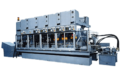
A rolling machine is a machine tool for plastic forming by applying a strong force to a material.

Metal has a property called “plasticity” that prevents it from returning to its original shape when a certain amount of force is applied. Plastic forming is a processing method that takes advantage of this property. In rolling machines, a tool called a die is pressed strongly against a rotating workpiece to transfer the shape of the workpiece, which is then plastically deformed into the required shape.

They are often used in forming processes such as screws. Cutting, in which the workpiece is cut, is a comparable process. Unlike cutting, form rolling does not produce chips and waste material.

It also has the advantage of shorter machining time and longer tool life, making it a more productive and efficient machining method compared to cutting. Furthermore, the strength of the material can be increased because the fibers of the material are connected without cutting.

Uses of Rolling Machines

Rolling machines are used to form screws, gears, and involute splines and serrations. Initial investment is required because dies must be prepared according to the specifications and shape of the product.

In addition, the setup time to switch between different types of products tends to be long. Therefore, they are not suitable for small-quantity, high-mix production.

Once setup is done, the tool life is long and product accuracy is stable, making it superior for small-lot, high-volume production. Also, machining time can be reduced compared to that of cutting.

Principle of Rolling Machines

Rolling machine processing can be broadly classified into round die rolling, flat die rolling, and planetary rolling.

1. Round Die Form Rolling

Circular die form rolling is a forming process in which the workpiece is sandwiched between two or three round dies rotating at the same speed. The principle remains the same: the dies are pressed against the workpiece by hydraulic or other force.

By changing the distance between the dies, the dimensions of the workpiece can be adjusted as desired. Because of its excellent machining applicability, it is also widely used for processes other than thread rolling. On the other hand, productivity is inferior to other thread rolling methods because the material to be processed is supplied and discharged at the same location.

Round die form rolling can be divided into three types according to its processing method. The other is the “push-in” form rolling, in which the workpiece is pushed in by hydraulic pressure or other means while the space between the dies is closed, and the “through” form rolling, in which the workpiece passes through the closed dies.

Through-feed form rolling is used for workpieces with leads, such as screws and worm gears. It is important to select the most suitable forming method considering the shape of the product.

2. Flat Die Form Rolling

Flat die form rolling is a forming process in which the workpiece is sandwiched between a pair of flat dies and the dies are moved in parallel as the workpiece rotates.

This is a highly productive method and suitable for mass production of general-purpose screws.

3. Planetary Form Rolling

Planetary form rolling is a method of processing by feeding the workpiece between the inside of a fixed die and a rotating round die.

Since the distance between the dies cannot be changed, the applicability of the process is limited. However, productivity is high, and this method is often used in the mass production of general-purpose screws.

Other Information on Rolling Machines

1. Automation of Rolling Machines

Rolling machines can be applied to a wide variety of parts processing, other than screws. In addition, there are numerically controlled, automated “form rolling machines” that can be used for advanced form rolling. This is due to the industry’s desire to shift parts processing from cutting, which tends to waste material, to plastic forming, which offers higher yields.

Computer-controlled rolling machines can achieve higher product precision than conventional rolling machines because the left and right spindle stands allow machining to proceed while absorbing load fluctuations while maintaining the center-to-center distance between the two dies mounted on the ram.

Another notable feature is the ability to accommodate an increase in the number of tool axis control axes. For example, in the case of a 7-axis computer-controlled form rolling machine, the spindle rotation, tilt angle, and distance between spindles can each be independently controlled, allowing more complex and precise movements than those used in a conventional round die form rolling, such as yose form rolling and through form rolling.

2. Advanced Control of Rolling Machine Dies

Automation of rolling machines has led to the development of new processing methods that have evolved from conventional round die rolling, such as reciprocating and multiple rolling.

Reciprocating form rolling is a form rolling process in which the dies rotating in the same direction are synchronized, alternating between forward and reverse rotation. The advantage of this method is that it suppresses the amount of movement of the workpiece as it moves and avoids contact with non-machined parts, thus facilitating the manufacture of high-machined parts that require repetitive machining.

Multiple-form rolling is a processing method that allows different patterns to be rolled in multiple locations in a single operation. This is achieved by feeding the workpiece into the exact position by means of a servo-controlled slide table. With a conventional rolling machine, two or more machines are required to process multiple parts, but with multiple rolling, only one machine is needed.

カテゴリー
category_usa

Leak Detection Band

What Is a Leak Detection Band?

A leak detection band is a band-shaped sensor.

It is used in leak detectors or liquid leak detectors as a safety device to detect leaks or leaking liquid. When leaked water or liquid comes into contact with the sensor strip, the electrical resistance of the strip changes.

After detection, the sensor can be used again by completely wiping off the leaked water/liquid, thus offering excellent durability. There are two types of leak detection strips: those installed on the floor and those installed around pipes.

Uses of Leak Detection Bands

Leak detection bands are widely used in a variety of locations due to their superior performance and diverse applications.

1. Houses and Buildings

Leak detection bands play an important role in homes and buildings. They are installed in hidden places such as under floors and inside walls to detect water leaks and burst pipes. They enable early detection of leaks and minimize damage to buildings and facilities.

2. Commercial Facilities and Offices

Leak detection bands are widely used in commercial facilities and offices. They are installed around water fixtures such as toilets, kitchens, and washing machines, and around the plumbing of equipment. When a leak is detected, an alarm and automatic shut-off function are triggered to minimize damage. This helps in the maintenance and management of the facility and the smooth operation of the business.

3. Industrial Facilities and Manufacturing

Leak detection bands also play an important role in industrial and manufacturing facilities. Early detection of leaks is critical, especially where chemicals and pharmaceuticals are handled. Leak detection bands are installed at the bottom of tanks and containers to detect leaking liquids and ensure the safety of the work environment.

4. Medical and Research Facilities

Leak detection bands are used in medical and research facilities to protect valuable laboratory materials and samples. They are installed in laboratories, freezers, refrigerators, and other water areas to prevent damage caused by water leaks or liquid leakage.

They are also used to detect leaks around cooling piping and cooling equipment such as boilers and in under-floor piping.

Principle of Leak Detection Bands

The leak detection band detects water and liquid leaks by means of an electrode-to-electrode resistance detection method.

1. Normal Condition

Under normal conditions, there is no current flowing between the two leak detection bands, and the electrical signal flowing through the bands is cut off by the terminator, creating an open loop between the band electrodes.

2. In Case of Abnormality

When water or liquid begins to leak, the leak detector detects the electrical signal flowing through it, and if the strength of the electrical signal exceeds a set value, an alarm is issued to indicate a water or liquid leak.

In some cases, the leak detection band itself may break and become defective. However, some detectors can detect a disconnection of the leak detection band and issue an alarm to prompt repair, judging that the disconnection detection signal that flows through the leak detection band does not return to the detector due to disconnection as an abnormality.

In addition, since detection is based on a change in resistance, once water or liquid leakage is detected, the sensor can be returned to the normal resistance range by wiping off water or liquid, so it can be used as a sensor again immediately.

Types of Leak Detection Bands

The most common type of leak detection band is one that detects water or liquid leakage based on changes in the resistance of the two leak detection bands of the leak/liquid sensor section. There are several types depending on the shape, material, and function of the sensing strips in the detection section.

There are two types of detection zones, the basic strip type and the point type.

1. Strip Type

Water or liquid leakage can be detected anywhere that the installed sensor section is located.

2. Point Type

As the name suggests, this type detects water and liquid leakage at a single point and is used when the location of the leakage is narrowed down and only that point is to be detected.

There are several different materials and functions to choose from, taking into consideration the location where the detection zone is installed. Compared to the general type, there are those with superior resistance to high temperatures and chemicals, those made of different materials, those that can be used in environments with high dust and humidity, and those that can be installed in pipes as opposed to those that are laid on the floor.

カテゴリー
category_usa

Multitasking Machine

What Is a Multitasking Machine?

Multitasking Machines

A multitasking machine is a machine that combines an NC lathe and a machining center.

It can perform multiple machining processes at once with high accuracy. In general, multitasking machines that combine lathe and machining center functions can perform multiple angles of machining on the same workpiece, thereby reducing machining time, increasing work efficiency, and improving quality. Moreover, the two machines do not need to be installed separately, allowing for more efficient use of space.

There are two types of multitasking machines: those that mainly use machining centers and those that mainly use NC lathes. The machining center-driven type is more accurate than the lathe-driven type and is suitable for machining complex shapes. On the other hand, the NC lathe-driven type is suitable for machining large-diameter parts and parts with a high small-diameter-to-length ratio.

Multitasking machines allow multiple processes to be handled at once, simplifying the process, increasing work efficiency, and improving quality. It also improves space efficiency in the factory because it reduces the number of places to place machines. It is important to select the appropriate multitasking machine according to the size, shape, and material of the workpiece.

Uses of Multitasking Machines

A multitasking machine is a machine that combines several functions into one and is capable of a wide variety of machining operations. As a result, they are used in a wide range of fields, including automotive and aircraft parts, medical devices, and industrial equipment.

Multitasking machines are particularly suited for manufacturing parts that require complex shapes and high-precision machining. For example, multitasking machines are needed to process high-strength aluminum alloys and titanium alloys for aircraft parts. They are also used in the medical field to manufacture precision parts such as artificial joints and dental implants.

Furthermore, multitasking machines can increase productivity. Combining multiple machining functions into one simplifies the machining process and reduces work time, thereby improving productivity. Another advantage of using a single machine for multiple machining functions is that it takes up less space.

Principle of Multitasking Machines

Multitasking machines are available in two types: machining center-based types and turning center-based types, which are mainly NC lathes. The machining center-based type has a rotary table that enables turning operations, while the turning center-based type has an NC lathe spindle and integrates multiple machining functions by attaching tools.

Both types contribute to saving factory space and shortening process procedures and are suitable for machining various shapes.

1. Machining Center Base Type

The machining center-based type has cutting functions as a conventional machining center, and the rotary table rotates like a lathe, enabling turning operations. The latest models can control 5 axes simultaneously and complete machining in a single process. This type is suitable for machining large objects and can shorten the process procedure.

2. Turning Center Base Type

The turning center-based type has the main spindle of the NC lathe, and the spindle is stopped and rotated at an arbitrary angle. Tools are mounted on the turret, and functions such as drilling, boring, and milling can be added.

The opposed dual-spindle models automatically pass to the second axis for full machining after machining is completed on the first axis, thus improving machining accuracy since machining is completed in a single installation.

Other Information on Multitasking Machines

Machines used in combination with Multitasking Machines

Multitasking machines are capable of advanced machining, but they cannot complete machining by themselves. Three types of machines can be used in combination with multitasking machines.

1. Measuring Machine
After machining with a multitasking machine, there are measuring instruments to measure its accuracy. For example, there are 3D measuring instruments and shape measuring instruments, which can measure the shape with high accuracy. By using measuring instruments together, machining accuracy can be checked.

2. Tool Presetter
Multitasking machines can use multiple tools, but changing those tools can be time-consuming. The tool presetter can be used to align tools in advance before changing them. This reduces tool change time and improves productivity.

3. Other
Since machining operations on multitasking machines are often monotonous and heavy, robots are sometimes combined. For example, they can automatically attach tools and move workpieces. In addition, multiple multitasking machines can be linked together to produce products automatically.

カテゴリー
category_usa

Shape Measuring Machine

What is a Shape Measuring Machine?

A shape-measuring machine is a device used to measure the roundness of an object with a circular cross-section, such as a cylinder or a sphere.

Roundness is defined in JIS B 0621 as “the amount of deviation of a circular object from a geometrically correct circle”. This means that when the cross-sectional shape of a measured object is sandwiched between two geometrically correct concentric circles, the roundness is expressed as the minimum difference in radius between the two circles.

There are two types of shape-measuring machines: the stage rotation type, where the detector is fixed and the object to be measured is rotated by a rotation stage, and the probe rotation type, where the detector rotates while the object to be measured is fixed.

Usage of Shape Measuring Machines

Shape-measuring machines are used to measure the roundness of various objects, such as parts, in a single cross-section. For example, in hydraulic circuits, valves, and seals, strict dimensional tolerances are required to ensure oil sealing and air tightness.

In bearing parts, roundness is an important characteristic for smooth and frictionless bearing function. It is also used for quality assurance of mechanical parts that require high precision. The purpose of measuring roundness is not only to measure the dimensional shape of shafts but also to measure surface properties.

Principle of Shape Measuring Machine

As mentioned earlier, there are two types of shape-measuring machines, and the difference is due to the difference in their operation. Both have their merits and demerits, but here we will discuss the principle of the rotary table type, which allows for higher precision measurements.

A rotary table-type shape measuring machine consists of a rotary table capable of detecting the rotation angle using a rotary encoder and a detector that detects displacement of the workpiece surface synchronized with the rotation of the table. While the object to be measured is placed on the rotary table and rotated, the displacement of the surface of the object to be measured is detected by a probe. The roundness is determined from the profile obtained by recording the angle of rotation and the displacement of the workpiece surface over 360°.

Care must be taken in roundness measurement because any misalignment between the center axis of the measurement target and the rotation during rotation will cause runouts and lead to errors. Also, if the angle between the axis of rotation and the displacement direction of the probe is not perpendicular, it will lead to errors.

Other information on Shape Measuring Machines

1. Reference Circle and Types of Roundness

When evaluating roundness, it is necessary to define a reference circle as a standard. There are four types of reference circles, and the roundness is defined according to the reference circle.

Least Squares Circle (LSC)
The least-squares circle is a reference circle in which the area outside and inside are equal when the reference circle is applied to the object to be measured. The difference between the distance of the nearest part and the farthest part from this least-squares reference circle is evaluated as the least-squares circularity.

Minimum Zone Circle (MZC)
The minimum area reference circle is the concentric circle with the smallest difference between the diameters of the two circles placed between the object to be measured from the outside and the inside.

Minimum Circumscribed Circle(MCC)
The minimum circumscribed circle is the circle that can enclose the entire measurement object and has the smallest diameter. The furthest distance from the minimum circumscribed circle to the contour of the object is evaluated as the minimum circumscribed circularity.

Maximum Inscribed Circle (MIC)
The maximum inscribed circle is the largest circle inscribed within the object. The furthest distance from the maximum inscribed circle to the contour of the object is evaluated as the maximum inscribed circularity.

2. Difference between Roundness and Cylindricity

Cylindricity is a geometric tolerance similar to roundness. The difference between the two is the range of evaluation. While roundness is evaluated on an arbitrary cross-section, cylindricity is evaluated with a certain range in the axial direction.

Since the evaluation range is wider than that of roundness, it is more difficult to ensure accuracy. It is important to determine whether to indicate roundness or cylindricity based on the function of the part. Roundness can be evaluated for shapes with different diameters in different cross sections, such as tapered shapes, while cylindricity can only be indicated for cylinders with the same diameter in the axial direction.

カテゴリー
category_usa

X-ray microscopes

What is an X-ray microscope?

An X-ray microscope is a microscopy technique that uses X-rays as a light source to observe the structure of an object.

X-ray microscope mainly uses transmission (absorption) X-rays and fluorescent X-rays, which are highly penetrating X-rays that can produce contrasting images by taking advantage of the attenuation reactions inherent to the internal structure, thickness, and composition of the material.

In addition, by rotating the specimen and constructing a 3D image from the continuously acquired images, it is possible to obtain a tomographic image (so-called CT). In general, spatial resolution in microscopy using electromagnetic waves depends on the wavelength of the electromagnetic waves. Since the wavelength of X-ray is 100 to 10,000 times shorter than that of visible light, it is possible to obtain a high-resolution image.

Uses of X-ray microscope

X-ray microscope is mainly used for research and development in the industrial field as well as for inspections at manufacturing sites. It can also be used to evaluate the structure of rocks and other materials to obtain parameters for characterization as new raw materials.

In the semiconductor manufacturing field, it is increasingly used to characterize products that have undergone ultrafine processing. When observing biological samples that contain a large amount of water, images with high contrast can be obtained by using the X-ray wavelength range where water absorption is low.

Principle of X-ray microscope

X-ray microscope uses X-rays to irradiate a sample and obtain images and perform component analysis by using the transmission (absorption) X-rays and fluorescent X-ray signals obtained from the material. The wavelengths of the X-rays used are often called soft X-rays (1-10 nm). In particular, the region from 2.3 to 4.3 nm is called the “water window” because water absorption is extremely low, and is used for observation of biological samples.

X-ray microscopies are classified into two types: those that use X-ray transmittance as a contrast to acquire images, and those that detect fluorescent X-rays generated by X-ray irradiation. X-ray fluorescence is a signal produced by the emission of X-rays corresponding to the energy difference between the inner and outer shells when outer-shell electrons relax into holes created by the excitation of inner-shell electrons in a material by X-ray irradiation.

Since fluorescent X-rays have wavelengths unique to each atom, they can be applied to elemental analysis. X-ray microscopes can also be broadly classified into two types, depending on the optical system and the presence or absence of optical elements. X-ray microscope without optical elements uses the projection magnification method and the contact method for observation.

Since the X-ray image cannot be magnified by using a lens, the sample is physically separated from the imaging surface and the image is magnified and projected. The imaging method using optical elements is realized by using zone plates with light commentary or mirrors that utilize total or multilayer reflection.

X-ray microscope

1. The difference between X-ray microscope and Electron microscopy

X-ray microscopes use X-rays as their light source, whereas electron microscopy uses electron beams to illuminate the specimen and magnify the image. An electron beam is a fast stream of electrons. An atom is composed of a nucleus made up of protons and neutrons, with electrons orbiting it. When protons, neutrons, and electrons are accelerated to very high speeds in a device called an accelerator, they become radiation in the form of proton, neutron, and electron beams.

Unlike X-rays, electron beams are particle beams and therefore have limited penetrating power. The penetration power of an electron beam is determined by the acceleration voltage: the higher the acceleration voltage, the deeper the electrons can penetrate, and the lower the density of the irradiated object, the deeper it can penetrate.

Transmission Electron Microscope (TEM)
A thin-film sample is irradiated with electron beams, and the electron beams transmitted through the sample are passed through an electron lens to produce an enlarged image on a fluorescent plate illuminated by the electron beams. The electron lens bends the electron beam by means of an electric or magnetic field to form an image.

Scanning Electron Microscope (SEM)
A narrowly focused electron beam is irradiated in a vacuum to scan the surface of a sample to detect secondary electrons and reflected electrons emitted from the sample. Secondary electrons are those emitted by the irradiated electron beam that knocks out other electrons in the sample, while reflected electrons are those emitted by the irradiated electrons that are reflected from the surface of the sample.

When an X-ray detector is attached to a scanning electron microscope, it can be used as an X-ray analyzer to determine the type and amount of elements contained in a sample.

2. Scanning X-ray microscope

This is a type of X-ray microscope that uses hard X-rays as a probe. Hard X-rays have a short wavelength of around 0.1 nm, and in principle, high resolution is possible. In addition to transmission (absorption), refraction, and reflection, interactions with materials include photoelectrons, fluorescent X-rays, elastic scattering, inelastic scattering, magnetic absorption and scattering, and many others.

Furthermore, its high transmissivity allows for non-destructive observation and is used for atmospheric measurements. Scanning X-ray microscopes consist of a focused X-ray beam, a stage for scanning the sample, and a detector. While scanning the sample, X-ray analysis (transmitted X-ray, fluorescent X-ray, scattered X-ray, etc.) is performed to visualize various types of information.

カテゴリー
category_usa

Super Engineering Plastic

What is Super Engineering Plastic?

Super engineering plastic is a type of engineering plastic with superior heat resistance.

General plastics are heat-sensitive and are not suitable for use in high-temperature environments or for parts where frictional heat is generated. They are also susceptible to degradation from ultraviolet rays, which limits their outdoor use.

Super engineering plastics are a new material that overcomes these shortcomings of plastics.

Uses for Super Engineering Plastics

Super engineering plastics are expected to replace metal parts because of their high heat resistance, mechanical properties, durability, and ability to be mass-produced. Super engineering plastics with high mechanical strength and heat resistance, such as polyetheretherketone, polyphenylene sulfide, and polyamide-imide, can replace parts around automobile engines, electrical parts, valves, pumps, and other components that previously could only be realized with metal.

Super engineering plastics are also increasingly being used for gears and bearings in industrial equipment, aircraft parts, and medical equipment parts that require high reliability. They are also used in the electrical and electronic fields that require high electrical insulation and heat resistance.

Characteristics of Super Engineering Plastics

Although there is no clear definition of super engineering plastics, they are generally characterized by their ability to be used at temperatures of 150°C or higher for extended periods and by their extremely high mechanical strength. Super engineering plastics are also classified as those with extremely high heat resistance, cold resistance, and chemical resistance, even if their mechanical properties are not that high, such as fluoropolymers.

In terms of high heat resistance and mechanical strength, thermosetting resins, which are cured by three-dimensional cross-linking when heated during molding, also fall under this category. However, they must be thermoplastic resins to be classified as engineering plastics or super engineering plastics. Thermoplastics can be reversibly melted and solidified, and thus are characterized by high flexibility in the molding process and recycling.

Plastics are formed by the aggregation of polymer chains. In engineering plastics and super engineering plastics, each molecular chain is long and the constituent molecules have strong intermolecular forces. As a result, they have high crystallinity, high strength, and heat resistance. In addition, engineering plastics and super engineering plastics can be further enhanced in mechanical strength and chemical stability by adding glass fiber or carbon fiber.

Types of Super Engineering Plastics

There are several types of super engineering plastics, each with different characteristics.

1. Polyetheretherketone (PEEK)

Maintains high mechanical strength even at high temperatures, with a continuous use temperature of 250°C. It also has excellent chemical resistance, hot water resistance, and abrasion resistance.

2. Polyphenylene Sulfide (PPS)

Maintains high mechanical strength even at high temperatures in continuous use temperatures of 200~240℃. It has excellent chemical resistance and dimensional stability and is flame retardant (self-extinguishing) due to the presence of aromatic rings in the molecule. Reinforced grades filled with glass fiber or carbon fiber are also available.

3. Polytetrafluoroethylene (PTFE)

PTFE is a fluorinated resin, well known by the registered trademark Teflon of Du Pont de Nemours and Company. It has top-class chemical resistance, lubricity, and electrical insulation properties, but its mechanical strength is inferior to that of other super engineering plastics.

4. Polyimide (PI)

An abbreviation for a resins with imide bonds. In the case of super engineering plastics, it refers to aromatic polyimides with aromatic groups in their molecule. It has the highest class of heat resistance, with continuous use temperatures of 260-300°C. It also has high insulation properties, making it suitable for electronic components. It is also widely used in electronic components because of its high insulation properties.

5. Polyamideimide (PAI)

PAI has the second-highest heat resistance after polyimide at a continuous operating temperature of 260°C. It also has excellent mechanical strength, chemical resistance, and electrical insulation properties.

6. Polyethersulfone (PES)

Amber-colored, transparent resin with excellent impact resistance at a continuous service temperature of 170°C. It has excellent chemical and hydrolysis resistance. It also has high resistance to chemicals and hydrolysis, and is flame retardant (self-extinguishing) because most of its molecules are aromatic rings.

カテゴリー
category_usa

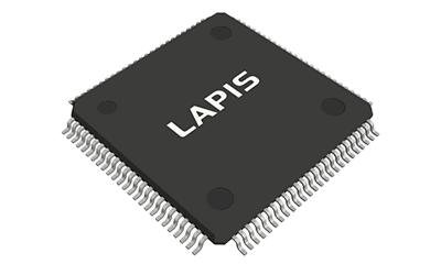
32-Bit Microcontroller

What Is a 32-bit Microcontroller?

32-Bit Microcontrollers

A 32-bit microcontroller is a microcontroller with a maximum instruction code bit width of 32 bits and a data bit width of 4 to 32 bits.

Microcontrollers are manufactured as semiconductor chips, and in addition to 32-bit microcontrollers, there are 4-bit, 8-bit, and 16-bit microcontrollers. 32-bit microcontrollers are at the highest level and have extremely high processing power.

Uses of 32-bit Microcontrollers

As evident in various home appliances that are labeled “microcontroller-equipped”, microcontrollers are utilized in a wide range of modern electrical products, including those used in industrial applications. LED displays that indicate operational states typically use 4-bit microcontrollers, while 8-bit microcontrollers are used for controlling white goods, and 16-bit microcontrollers are used in remote control products, depending on the required performance.

A 32-bit microcontroller, which has the highest level of processing performance, is used in situations where large amounts of data are processed at high speed or complex processing is performed at high speed, such as image processing for TVs and DVDs, data communications in communications equipment, engine control and driving control in automobiles, and image recognition and motion control in robots.

Principle of 32-bit Microcontrollers

Most 32-bit microcontrollers are equipped with not only standard peripheral circuits but also specialized processing circuits for specific applications, as complex and high-speed processing is required.

For example, applications related to image processing such as TV, DVD, and image recognition require a large number of sum-of-products operations. Since executing this operation in software requires a large number of steps and is extremely time-consuming, a dedicated circuit for high-speed processing in hardware is integrated to speed up the process.

In addition, for communication-related applications, a dedicated circuit called a UART that converts serial to parallel is used to process data that is mixed with various communication protocols.

Thus, 32-bit microcontrollers are also called system LSIs because they perform complex processing at high speed on a single chip by incorporating dedicated circuits for each application.

Today advances in semiconductor technology have made it possible to integrate one billion transistors on a single semiconductor chip. As a result, smartphones and other devices can integrate multiple dedicated circuits and CPU cores on a single chip and run user-developed applications, and the boundary between microcontrollers and processors is becoming blurred.

Other Information on 32-bit Microcontrollers

1. Characteristics of 32-bit Microcontrollers

32-bit microcontrollers are available in two types of instruction bit widths depending on the architecture of the Central Processing Unit (CPU): 32-bit fixed-length and 4~32-bit variable-length. Variable-length instructions are smaller in program size.

As the name “controller” implies, microcontrollers are used for controlling various devices and have limited applications compared to microprocessors found in servers, PCs, and other general-purpose applications.

Another difference between microcontrollers and microprocessors is the emphasis on real-time performance. To control devices, processing must be done on the fly, and the Operating Systems (OS) used in 32-bit microcontrollers are real-time OS that differ from the usual Windows OS. A typical real-time OS is the Japanese TCP/IP OS. A typical real-time OS is uITRON, a product of Japan’s TRON project.

In a 32-bit microcontroller, various timer/counter circuits, A/D converters, D/A converters, I/O port circuits, LCD driver circuits, memory circuits, etc. are integrated into the same semiconductor chip with a 32-bit CPU as the core.

2. About ARM Core

The core of a 32-bit microcontroller is the CPU core, which greatly influences processing performance and ease of use, of which the ARM core is the most representative.

The ARM core is the core of the microcontroller found in most smartphones and information appliances for both iOS and Android and was developed by ARM, a company founded in the UK in 1990. It is a CPU core with a fixed-length, concise instruction set architecture while also having the features of a variable-length instruction set. Its simple circuit structure makes it easy to apply to the progress of semiconductor miniaturization, and it is characterized by its low power consumption and high processing power.

Low power consumption is essential for mobile devices that require batteries and industrial devices that are in constant operation. The arrival of the IoT era, in which various objects are connected to the network, has accelerated the demand for microcontrollers with both low power consumption and high performance.

ARM cores were licensed at the architecture and circuit levels, and were introduced in many companies, especially for mobile PCs and smartphones, rapidly expanding their market share.

カテゴリー
category_usa

Piezoelectric Device

What Is a Piezoelectric Device?

Piezoelectric devices are passive devices that control and detect micro-operation using the piezoelectric and inverse piezoelectric effects that occur in dielectric materials such as quartz and quartz.

Because of their simple structure that does not require gears or motors for operation, piezoelectric elements are smaller than other micro-operation mechanism elements.

Uses of Piezoelectric Devices

Piezoelectric devices are mainly used in devices that detect and control micro-motion for industrial applications.

For example, piezoelectric devices are used in vibrometers, where minute changes in force due to vibration are input to the piezoelectric device as pressure, and the voltage generated in the piezoelectric device under pressure is output to obtain a voltage value that is quantified as the magnitude of the vibration.

Piezoelectric drive systems are also used in the stage motion of microscopes, interferometers, and other equipment that requires precise motion.

Piezoelectric device components for such drive systems are called piezoelectric drivers or piezoelectric actuators, and multilayer actuators with multiple layers of piezoelectric devices are also commonly used components.

In these devices, minute movements are achieved by applying minute pulse currents to the piezoelectric devices. Piezoelectric devices are suitable for situations where high responsiveness and precise motion control are required.

Principle of Piezoelectric Devices

Piezoelectric ceramics serve as the primary materials in piezoelectric devices. Piezoelectric materials have polarity, which is an electrical distortion inside the crystal.

A piezoelectric device consists of a piezoelectric material sandwiched between a positive electrode and a negative electrode.

By applying voltage between the electrodes, pressure is applied to the piezoelectric body, which expands, contracts, and displaces as shown by the blue arrow depending on the magnitude of the voltage, and this displacement is used as the driving force, etc. In addition, it is also possible to detect voltage by applying pressure that deforms the piezoelectric device in the opposite direction.

Under normal conditions, the crystal lattice inside the piezoelectric element remains electrically stable by taking in ions from the atmosphere. However, when voltage is applied, the balance is easily disrupted, leading to a change in polarity within the crystal. As a causing the crystal lattice expand and contract in the direction which indicates the displacement of the piezoelectric material.

The piezoelectric device uses this polarity to efficiently transform electrical energy into deformation energy of the device, and is composed of a piezoelectric material sandwiched between electrodes.

In response to the voltage applied between the electrodes, pressure is applied to the piezoelectric body, causing it to deform.

The piezoelectric body can also detect voltage when pressure is applied in the opposite direction.

The deformation of the piezoelectric material in this case is at the level of a few microns at most, due to distortion deformation using the electronic polarity of the crystal lattice of the piezoelectric material.

Therefore, in general, only a few microns of driving force can be expressed, and multiple piezoelectric devices must be combined and stacked if a larger driving force is to be secured.

How to Select Piezoelectric Devices

It is necessary to determine the piezoelectric device that operates appropriately depending on whether the material in which the piezoelectric device is installed and operated is a mass load or an elastic load.

In particular, when the piezoelectric device is used to operate an actual moving structure held via an elastic member such as a spring, it will be under elastic loading conditions. As load is applied to the piezoelectric device, the elasticity of the spring will push back the force exerted by the piezoelectric device, changing the way the force is transmitted.

Specifically, the case in which the force generated when the piezoelectric device presses down on the driving member is transmitted directly to the actually moving component is called mass loading. A constant force in the direction of the blue arrow is applied continuously from the time the voltage is applied to the piezoelectric device.

On the other hand, the elastic load described above is a case in which the force generated when the piezoelectric device presses down on the driving member is transmitted to the actually moving component via an elastic member such as a spring.

From the time the voltage is applied to the piezoelectric device, it is pressed against the resistance of the spring and the force applied to the component gradually increases until it reaches a constant force.

Therefore, if the piezoelectric device can only provide a constant voltage when it is pressed through an elastic member such as a spring, the amount of movement will differ between the first and second halves of the operation.

In addition, since piezoelectric devices have a fixed stroke length, it is important to select a piezoelectric device with a stroke length that can achieve the desired motion.

Piezoelectric Device Materials

There are two types of materials with piezoelectric effect: ceramic-based and film-based.

1. Piezoelectric Ceramics

Lead zirconate titanate (PZT)
PZT is the most widespread piezoelectric ceramic and is used in a wide range of applications primarily in buzzers, vibration sensors, and actuators.

2. Lithium Tantalate (LT)

This single-crystal material is used in electronic devices due to its high stability. The most common application is in electronic devices called SAW filters, which allow only specific radio waves to pass through. It is widely used in cell phones.

3. Piezoelectric Film

Polyvinylidene fluoride (PVDF)
PVDF is a resin film with piezoelectric properties. Although its displacement capacity is not as high as that of ceramics, it can be produced inexpensively and processed into various shapes. It is widely used in home appliances such as proximity sensors for self-propelled vacuum cleaners and touch sensors.

Examples of Products in Which Piezoelectric Devices Are Used

1. Piezoelectric Devices for Lighters

Piezoelectric devices are used in the ignition parts of electronic lighters and gas stoves, taking advantage of the fact that they generate a high-voltage charge when a shock is applied.

While flints (ignition stones) wear out with each use, piezoelectric devices used in electronic lighters can be used semi-permanently as long as they are not damaged, making them suitable for use in refillable gas lighters and the like.

2. Speakers Using Piezoelectric Devices

Piezoelectric devices are also used as sound components, taking advantage of their ability to expand and contract when an electric signal is applied. A thin plate of piezoelectric ceramics is attached to a metal plate to obtain vibration amplitude using spreading vibration to produce a loud sound.

It is mainly used for notification sounds in home appliances, beeps in computers, electronic sounds in clocks, back-up sounds in car cabins, and click sounds in audio equipment.

Some high-end audio products are equipped with piezoelectric speakers as tweeters that produce sounds around 20 kHz, which are barely audible to the human ear, and some produce the effect of broadening the sound in classical music, etc.

3. Piezoelectric Actuators

Piezoelectric devices are also suitable as actuators (drive units) for pushing and pulling objects, taking advantage of their ability to expand and contract with electric signals.

Piezoelectric actuators are used in the drive unit of inkjet printers to realize high-precision ink ejection and dispensing functions for pushing out liquid.

Actuators using piezoelectric devices have the advantage of being smaller than actuators using electromagnetic coils, but they are used only in applications that require minute, high-precision drive amplitudes because they are not as large as coil-type actuators in terms of vibration amplitude.

カテゴリー
category_usa

Belt Heater

What Is a Belt Heater?

Belt heaters are belt-shaped heaters designed to heat objects by covering the surrounding object.

It can heat objects regardless of their shape, and is used to heat objects that have complex shapes or are difficult to heat over an open flame. Depending on the material of the belt, this heater excels at heating objects in the range of human living temperatures up to around 200°C, and is used in a variety of fields.

Because they heat objects by converting electricity into heat, they can be heated as long as electricity is available. Since they require a few other tools, they are easy-to-use heaters with a low degree of difficulty.

Uses of Belt Heaters

Belt heaters are used in a variety of applications for heat retention and heating. They are used in a very wide range of fields, including medical, health, and physical/chemical equipment. In winter in cold regions, belt heaters are also used to prevent freezing of pipes such as water pipes, making them an important heater for daily life.

Because they heat evenly over a surface when heated, they are also used in applications where localized temperature changes that can cause damage, such as during thawing, are not desirable. When using belt heaters, be very careful when using sharp tools such as cutters nearby to avoid cutting or damaging the belt section.

In particular, when removing a belt heater, the belt portion is often damaged along with the auxiliary jig (string, plastic wrap, etc.) that secures the heater to the object being heated. Also, be sure to check how the belt heater is attached when removing it.

Principle of Belt Heaters

Heaters heat objects by converting electricity into heat, and their performance as heaters is graded according to voltage and electrical capacity. It is also important that the belt, which serves as the heating part, be flexible enough to follow the various shapes of the object to be heated. When using the belt, it should be handled in such a way that it does not undergo extreme shape changes beyond its operating range.

If the circuit of the heater section where electricity flows is ruptured, the area to be heated may be localized, or the heating may stop or even cause a malfunction.

Structure of Belt Heater

Belt heaters consist of two major components: a lead wire that takes the power supply for heating and a belt that is the heating part. The temperature range that can be handled varies depending on the material used for the heating part.

Similar products called cord heaters and tape heaters are also available, but the difference is whether the heating part is in the form of a belt or not; the heating principle and structure are almost the same. It is recommended to select the shape that best suits the purpose of use.

How to Choose a Belt Heater

1. Material

Silicon rubber-like material is often used, but belts made of braided heat-resistant fiber (heat-resistant polymer fiber such as polyamide or polyester) are also used in areas where the heating temperature is high, and materials vary depending on the expected temperature range.

Rigid materials are not suitable for belts, as they must be able to follow the shape of the heated object. Other materials with the necessary resistance, such as electrical insulation, heat resistance, and chemical resistance, should be selected as needed to meet the needs of the application.

2. Shape

Depending on the size and shape of the object to be heated, belt heaters of various shapes, from thin to thick, and from short to long, are deployed in the market. In addition, in order to cover small-diameter objects to be heated, the belt must be thin in thickness to cover them well.

Select the shape of the belt heater by carefully checking what kind of shape you want to use, its length, and its ability to follow the object. When installing a new belt heater, it is important to select and design the best combination of heater length, voltage/capacity, and lead wire length for the intended use.

In some cases, it may be possible to hire a specialist to custom-build a belt heater to your specifications. We recommend the systematic introduction of belt heaters of various materials and shapes to make heating as efficient as possible.