カテゴリー
category_usa

Flap Seal

What Is a Flap Seal?

A flap seal is a rubber or plastic seal that provides protection and closes gaps without the use of adhesives. Commonly referred to as “trim seals” or “edge seals,” flap seals are versatile components in various applications.

Uses of Flap Seals

Flap seals find extensive use in construction machinery, agricultural machinery, special vehicles, and nursing and welfare equipment. In construction, they protect the periphery of fittings and prevent dust and dirt intrusion. In the industrial sector, flap seals serve as cushioning for machine doors and safety measures to protect edges of sheet metal and steel plates, reducing injury risks. Additionally, they are employed in rubber packing for dustproofing in train window frames and switchboard doors, as well as in wiring protection.

Features of Flap Seals

Diverse flap seal types exist, each suitable for different product uses and environments. TPE (thermoplastic elastomer), an eco-friendly material, merges resin and rubber properties, offering ease of processing and recyclability. The oil-resistant type is ideal for machining environments due to its superior oil resistance. PVC (polyvinyl chloride) and EPDM (ethylene propylene rubber) are also used, known respectively for their flame/weather resistance and cushioning properties. Furthermore, flap seals with an aluminum core are notable for easy and adhesive-free attachment.

カテゴリー
category_usa

Jet Cooler

What Is a Jet Cooler?

A jet cooler is a device that cools an object using vortex force. It is a compact cooling device that can be used in any location.

In addition to its small size, it has the following features:

  • Environmentally Friendly
    Other cooling systems use refrigerants such as chlorofluorocarbons, which can have a negative impact on the environment when released into the atmosphere. Jet coolers, on the other hand, are environmentally friendly because they only use compressed air.
  • Durable
    Jet coolers have no sliding parts and a simple structure, making them highly durable with minimal breakdowns over time.

Uses of Jet Coolers

Jet coolers find applications in soldering processes.

Soldering is a method of joining components by melting and hardening an alloy of tin and lead (solder) with heat, primarily used in electronic components.

Lead-free solder, now preferred for its reduced impact on human health, tends to harden unevenly. This can result in product defects such as cracks. Jet coolers are used to ensure uniform cooling for consistent solder hardening.

Principles of Jet Coolers

Jet coolers utilize vortex force to generate cold air.

Initially, a compressor is employed to supply compressed air into the device. The compression stores energy and generates a powerful force.

The compressed air passes through a vortex generator within the equipment. Inside the generator, the air is released tangentially, resulting in high-speed rotation and vortex formation.

As the vortex rotates, centrifugal force comes into play, causing an increase in pressure and density. Following Boyle-Charles’ law, an increase in pressure and density results in higher temperature.

The vortex moves toward the outlet. During this movement, the temperature decreases at the center of the vortex as the air expands. Heat is released from the center outward, creating a temperature difference between the center and the outer region of the vortex. The cooler central air is expelled from the outlet and used for cooling purposes, while warmer outside air is discharged in the opposite direction.

By repeatedly supplying compressed air, creating a vortex, and segregating air based on temperature, consistent and efficient cooling is achieved.

カテゴリー
category_usa

Pneumatic Cylinder


What Is a Pneumatic Cylinder?

A pneumatic cylinder is a type of cylinder that moves in a single direction when fluid pressure is applied.

It is characterized by its unidirectional operation and is returned to its original position by an external force, such as a spring or gravity. Pneumatic cylinders are cost-effective due to their relatively simple design and low manufacturing costs. They are also more compact and lightweight compared to double-acting cylinders, making them suitable for applications with space constraints and weight considerations.

Pneumatic cylinders offer predictable unidirectional motion, making control easy and reducing the risk of accidents or machine breakdowns due to incorrect operation.

However, their unidirectional nature makes them unsuitable for applications requiring complex movement patterns. For such cases, additional control devices or systems may need to be implemented to achieve multiple stopping positions, for example.

Uses of Pneumatic Cylinders

Pneumatic cylinders find a wide range of applications. Here are a few examples of pneumatic cylinder applications:

1. Automobiles

Pneumatic cylinders are commonly used in automotive braking systems. When the brake pedal is pressed, the pneumatic cylinder applies pressure to the brake pads, pressing them against the disc or drum to generate braking force.

Pneumatic cylinders are also frequently employed in vehicle suspensions. The movement of the cylinder controls the vertical motion of the wheels, enhancing ride comfort and vehicle stability.

2. Manufacturing

Automated machines and manufacturing lines utilize pneumatic cylinders for tasks such as assembling and sorting parts. These cylinders can automate assembly processes by extending a piston to move parts.

Pneumatic cylinders are also used for material extrusion in certain plastic and metal molding machines. They apply pressure to the mold, pushing the material out to create a specific shape.

3. Chemical Plants

Pneumatic cylinders are employed to control open/close mechanisms such as valves and gates in chemical plants. The cylinder’s motion is responsible for opening and closing these devices, regulating the flow and shut-off of fluids. They play a crucial role in fluid control within pipelines and piping systems.

Principle of Pneumatic Cylinders

A pneumatic cylinder consists of a cylindrical component known as the cylinder tube and a piston that reciprocates inside the tube. The piston is designed to fit snugly within the cylinder tube.

Since pneumatic cylinders operate in a unidirectional manner, the supply and discharge of fluid are carefully controlled. Fluid is introduced into the cylinder through a designated path.

When fluid is supplied to the cylinder, the pressure within the cylinder typically increases. This rise in pressure propels the piston in one direction. The piston’s movement is a result of the change in the internal volume of the cylinder.

After being extended, a pneumatic cylinder requires an external force to return it to its initial position once the fluid supply is stopped. This external force may be provided by a spring or gravity, with spring-based products being the more common choice. The external force returns the piston to the cylinder’s starting position, preparing it for the next operation.

How to Select a Pneumatic Cylinder

When choosing a pneumatic cylinder, it’s essential to consider the following factors:

1. Inner Diameter of the Tube

The tube’s inner diameter (I.D.) refers to the size of the cylinder’s interior. While a larger tube I.D. can generate higher pressure, it often results in a larger overall size. Conversely, a smaller tube I.D. is suitable for compact designs but limits pressure capabilities. The selection of the appropriate tube I.D. should align with your application’s requirements.

2. Stroke

Stroke refers to the distance the piston travels during reciprocation. Choose a stroke length that matches your application’s needs. A too-short stroke may not cover the required range of motion, while an overly long stroke could lead to an oversized cylinder that restricts the design.

3. Push-In/Pull-Out Characteristics

Select between push-in and pull-out based on fluid inflow requirements, depending on your specific application. The push-in and pull-out speeds may vary depending on the product.

4. Position Detection

Position detection devices, such as reed switches, limit switches, and micro switches, are used to detect the cylinder’s position and send/receive control signals. Choosing a pneumatic cylinder equipped with a position detection system facilitates integration with your control system. Reed switches are commonly used due to their space-efficient design, with products incorporating reed switches featuring a built-in magnet within the cylinder.

カテゴリー
category_usa

Cleanroom Shoe


What Is a Cleanroom Shoe?

Cleanroom shoes are specialized work shoes designed for use in cleanrooms. They are engineered to prevent the buildup of static electricity and the generation of dust.

These shoes are typically worn in conjunction with work clothes (cleanroom attire) to effectively control static electricity and minimize dust emissions. Cleanroom shoes are specifically designed to minimize the introduction of particulate matter.

This proactive approach prevents particulates from contaminating products and processes within the cleanroom environment. Cleanroom shoes adhere to strict hygiene standards and are suitable for use in environments and industries where cleanliness is paramount. In many cases, specialized materials are used to reduce the generation of static electricity.

It’s important to note that there are stringent regulations governing hygiene and dust control in cleanrooms. Therefore, it’s crucial to carefully select and use appropriate cleanroom shoes, as the type of shoes permissible depends on the cleanliness requirements of the specific cleanroom.

Uses of Cleanroom Shoes

Cleanroom shoes find applications in a variety of industries. Here are some examples of how cleanroom shoes are used:

1. Semiconductor Industry

In the semiconductor industry, where minute circuits and chips are manufactured, working in a cleanroom requires strict control of particulate contamination. Cleanroom shoes are essential for personnel to navigate the cleanroom environment while coming into contact with delicate components and equipment.

2. Medical Care

Cleanroom shoes are employed in operating rooms and other environments where any form of bacterial contamination is unacceptable. Airborne particulates are often responsible for bacterial contamination. The use of cleanroom shoes mitigates the generation and adherence of particulate matter, thereby reducing the risk of bacterial contamination.

In addition, in the pharmaceutical industry, where pharmaceuticals are manufactured in exceptionally clean environments, stringent hygiene measures are enforced in cleanrooms to prevent the entry of microorganisms and particulates. Workers are required to wear cleanroom shoes while conducting their tasks within these cleanroom facilities.

3. Food Processing Industry

In food factories and food processing facilities, maintaining strict food hygiene standards is of utmost importance. To minimize the entry of microorganisms and foreign substances, employees are required to wear cleanroom shoes. This enables them to carry out food production and processing operations while upholding cleanliness standards.

Principle of Cleanroom Shoes

Cleanroom shoes are constructed using specialized materials and are designed to minimize the infiltration of particulates and microorganisms. They are engineered to be dustproof, preventing particulate ingress. The exterior of these shoes is made from highly sealed materials to minimize particulate adhesion and ingress.

Additionally, cleanroom shoes are designed to have minimal gaps and openings. Given that static electricity can attract particulates and potentially damage products, cleanroom shoes are equipped with anti-static properties. The soles of these shoes often incorporate conductive materials and pathways to dissipate static electricity effectively. Furthermore, they are designed with hygiene in mind, featuring non-slip interior materials that are easy to clean and disinfect regularly. Cleanroom shoes are designed to be convenient to put on and take off.

How to Select Cleanroom Shoes

When choosing cleanroom shoes, it’s essential to consider the following factors:

1. Environmental Requirements

Understanding the specific requirements and regulations within the cleanroom environment is crucial. Different industries and environments may have varying requirements. Identifying environmental needs such as particulate control levels and electrostatic control requirements is paramount.

2. Size and Fit

Shoe size and fit are critical for comfort and safety. Selecting the correct size and ensuring a proper fit is essential. It’s important to ensure that the shoes are securely fastened and won’t slip during work.

3. Cleanliness

Hygiene is a top priority for cleanroom shoes. Verify that the shoe interiors are made of non-slip materials that are easy to maintain cleanliness. Additionally, confirm that the shoes are designed for easy donning and doffing, as well as simple cleaning and regular disinfection.

カテゴリー
category_usa

Pallet Transfer Module

What Is a Pallet Transfer Module?

A pallet transfer module is an automated system designed for the efficient transfer of raw materials, products, and the pallets used for their transportation within a production plant.

While material handling is a crucial aspect of factory operations, it does not directly contribute to profits and often requires significant labor, storage space, and equipment like forklifts. Automating these tasks with a pallet transfer module can lead to substantial labor and cost savings, while its general-purpose design simplifies the planning process.

Uses of Pallet Transfer Modules

Pallet transfer modules are commonly utilized in automated production lines, especially in the manufacturing of lithium-ion batteries and electronic components. They enable rapid loading and unloading, and their modular design allows customization in shape, size, and drive method to suit the specific requirements and constraints of the production facility.

Their modular nature also facilitates process adjustments, such as increasing, decreasing, or altering production stages, making them ideal for high-mix, low-volume production environments.

Principles of Pallet Transfer Modules

Pallet transfer modules achieve versatile pallet handling by integrating various components, including lifters for vertical movement, shifters for directional changes, rotators, linear movers, positioning systems, and sensors. Each module typically operates on its own power supply unit and air cylinder, allowing selective activation as required.

The design and installation standards of these modules are standardized for seamless interoperability. Safety features like pallet detection devices and robust drive systems are incorporated to prevent accidents.

Larger modules can handle and organize bigger pallets used for storing and transporting products and parts. They can also be integrated with a production control system for efficient management of part receipt and dispatch, as well as pallet reorganization in preparation for delivery.

カテゴリー
category_usa

Spring Guide Pin

What Is a Spring Guide Pin?

A spring guide pin is a type of guide pin designed for use in the center of a coil spring. It serves as a guide when the spring is activated. One end of the guide pin features a threaded portion, which is threaded into the base of the spring to secure it in place. The other end typically includes a hexagonal wrench hole or a similar feature for attaching the guide pin.

A similar product to the spring guide pin is the spring pin. Spring pins are created by rounding a spring plate to provide a gap at the mating part. These pins are then inserted into a pre-drilled hole, often used as hinges or to prevent the spring from slipping out by utilizing the spring’s radial force.

Uses of Spring Guide Pins

Spring guide pins find application in various machines for positioning and guiding springs. They also act as stoppers to prevent springs from getting damaged due to abnormal compression. Common uses of guide pins include springs for dies used in press work and clutch springs for automobiles.

Spring pins, on the other hand, are inserted into precision-drilled holes to secure them in place. They have a wide range of applications, including as stoppers and hinges for machinery and equipment, as well as for connecting, positioning, and preventing the rotation of parts. In addition, spring pins are used to hold rollers in place in roller chain equipment.

Features of Spring Guide Pins

Spring guide pins are often constructed from materials such as S45C, which undergo heat treatment and receive an iron oxide coating. Alternatively, stainless steel, brass, or chrome-plated brass may be used. The length of the guide pin should be designed to be less than the height of the spring when it is at its maximum compression, with an added safety margin. The diameter of the guide pin should be smaller than the minimum inside diameter of the spring during compression.

Another specification for spring guide pins involves the use of raw, non-heat-treated alloy tool steel. The pin diameter is typically about 2 mm smaller than the spring’s inner diameter to prevent damage caused by wear to the spring’s inner diameter. When used horizontally, the spring should undergo initial deflection.

Spring pins are crafted from materials like spring steel, phosphor bronze, or other springy plate materials that are rounded. Pins with straight mating parts offer high shear strength and are suitable for dynamic or impact loads. Corrugated pins are less prone to entanglement and are suitable for automatic insertion. Corrugated types designed for light loads are used when the pin thickness is thin, and the material in use is aluminum or resin.

カテゴリー
category_usa

Memory IC

What Is a Memory IC?
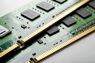
Memory ICs

A memory IC is a semiconductor device that is responsible for recording data in a processor-based system.

Memory ICs can be broadly classified into ROM and RAM. ROM (read only memory) is memory that is limited to reading data written at the time of manufacture. However, ROM also includes devices such as EEPROM and flash memory, which allow data to be rewritten.

RAM (random access memory) is a memory that can write/read data at a high speed. RAM is limited to temporary data storage applications because the recorded data disappears when the power supply that drives the memory device is turned off.

There are two types of memory structures: SRAM (Static Random Access Memory) and DRAM (Dynamic Random Access Memory), which allows a higher level of integration.

Uses of Memory ICs

Memory ICs are used in combination with processors to store program data and retain data during arithmetic operations. Memory ICs are installed in all processor-equipped devices and computers, from cell phones, tablet terminals, and personal computers to mainframes.

Generally, ROM stores program data, and the processor performs various processes according to that program data. At that time, data and information to be temporarily stored are written in RAM. Since RAM data is frequently rewritten, it is important for RAM to operate at high speed.

EEPROM, which is classified as a part of ROM, is also used to write adjustment data and other data, especially in electronic devices. Flash memory is used as a storage element in memory cards and SSDs (Solid State Drives), taking advantage of its characteristics as a ROM that can achieve a large memory capacity and can be rewritten.

Principle of Memory ICs

Memory ICs are equipped with a recording area in which many memory elements are arranged in an orderly fashion, address lines for specifying the data of individual memory elements, signal output lines for communicating the data of the memory elements to the outside world, and signal input lines for inputting data from the outside.

The processor used in combination with the Memory IC is also responsible for managing the data recording area of the Memory IC, so that when necessary data is read out, the data of that memory element is output to the signal output line by manipulating the address line. For data to be recorded in the memory, the address line is manipulated to specify the recording element, and the data is transferred to the signal input line.

The above is the flow of reading and writing signals to Memory IC. However, the internal circuit configuration and driving method of Memory ICs are completely different depending on the type.

Types of Memory ICs

Memory ICs can be broadly classified into ROM and RAM, each of which has several types.

1. ROM

Mask ROM
In mask ROM, a dedicated mask is fabricated according to the data to be written, and the data is written using this mask in the device manufacturing process. Therefore, the written data cannot be changed.

PROM (Programmable Read Only Memory)
A PROM is a write/erasable ROM that retains its memory contents even when the power is turned off.

EPROMs consist of an array of MOSFETs with floating gates, and data is written to them using a dedicated writing tool. However, these devices are rarely used today because they require ultraviolet irradiation when erasing data.

EEPROM (Electrically Erasable PROM) and flash memory are used instead. Both can be written or erased by receiving a control signal from a controller, but flash memory has become widely used in memory cards and other devices because of its structure that can achieve particularly large storage capacity.

The data is set to 0 or 1 depending on the presence or absence of a charge injected into the floating gate of the MOSFET. Since the injection and erasure of the charge is done using the tunneling effect, a high-voltage power supply circuit is built into the IC.

2. RAM

SRAM
SRAM uses a flip-flop circuit or similar device as the storage element, and once recorded, the contents are retained as long as power is supplied. Because it does not require a refresh operation like DRAM (see below), it consumes less power than a DRAM of the same memory capacity and can be read/written at high speeds.

However, the complex structure of the memory elements makes it difficult to achieve high density, and the unit manufacturing cost is high. Therefore, DRAM is suitable for applications where power saving and high speed are important. For example, it is often used as high-speed cache memory in computers, where it is placed between the processor and the main memory.

DRAM
DRAM uses one transistor and one capacitor to store data. In other words, the state of the capacitor with/without charge is defined as data 0/1. The transistor acts as a switch to accumulate charge in the capacitor.

The circuit configuration is simple, which allows for a high level of integration. However, because charge gradually leaks from the capacitor even when the switch is in the OFF state, data overwriting is periodically performed to prevent data corruption due to charge leakage. This is called a refresh operation, and is a function unique to DRAM.

カテゴリー
category_usa

Counter IC

What Is a Counter IC?

A counter IC is a digital circuit with a counting function. It is primarily used to count the frequency of specific events. Counter ICs are integrated circuits designed to increment (up-counting) or decrement (down-counting) a value stored in an internal register by one, based on specific events or clock pulses. They output the counting result when a target value is reached or an external device requests it.

While there are various counter ICs, the most basic type is the binary counter, which counts in binary For example, a 4-bit binary counter expresses values from 0 to 15 in binary. There are also counter ICs with different modes of operation, such as ring counters and Johnson counters.

Uses of Counter ICs

Counter ICs are used in various applications, including digital circuit design and control systems. Timers, sequential controls, and frequency dividers are examples of specific applications.

1. Timers

Counter ICs are used in timer circuits to measure specific time intervals or events. They are commonly employed in digital clocks and stopwatches.

2. Sequential Control

Counter ICs play a crucial role in sequential control circuits. They are used in sequential logic circuits and state transition machines to control devices or systems that operate in a specific order.

3. Frequency Divider

Counter ICs can function as frequency divider circuits by dividing an input signal’s frequency. This capability allows for the creation of signals with frequencies that are integer fractions of a higher-frequency input signal. Common applications include frequency synthesis and frequency control.

4. Event Counting

Counter ICs are used to count the number of times a particular event occurs. This application is seen in scenarios such as traffic surveys, where the number of vehicles or pedestrians passing by is counted.

5. Data Communication

Counter ICs are sometimes used in data communication circuits. They are used to set the number of data in serial communication or packet transmission.

Principle of Counter ICs

A counter IC consists of the following elements:

1. 1D Flip-Flops

D flip-flops are the main logic circuits used in counter ICs. Since this logic circuit can store one bit of information, various counter ICs are constructed by combining these elements.

A D flip-flop has a clock pin (CLK), a data input pin (D), a data output pin (Q), and its inverted output, and has the function of outputting the data input to the data output pin at the rising edge of the clock.

2. Counter

The basic configuration is that the inverting output is directly connected to the input pin and the data output pin is input to the data input pin of the next stage D flip-flop. By connecting N stages vertically, a binary counter of the power of 2 to the Nth power is created.

3. Frequency Divider

By connecting a D flip-flop between the terminals as described above, the output of the data input to the D terminal can be viewed as being divided by one-half. By using this function, it is possible to make a frequency divider with a counter IC.

In the case of a 4-bit binary counter, the frequency is 2 to the fourth power (16), which means that the output frequency is 1/16 of the input clock frequency. The 8-bit binary counter is 2 to the eighth power (256), which means that the output frequency is 1/256 of the input clock frequency. The output frequency is 1/256 of the input clock frequency.

Types of Counter ICs

There are various types of counter ICs. Typical examples are listed below:

1. Binary Counter

The most basic counter IC, counting in binary, an N-bit binary counter can represent a number from 0 to (2 to the Nth power-1).

2. Ring Counter

A ring counter IC whose internal bits are shifted sequentially with each clock cycle. The input pin of each flip-flop is connected to the output pin of the previous flip-flop, and the last output is fed back to the input pin of the first flip-flop. The function is such that a bit “1” is shifted to the next flip-flop in turn.

3. Johnson Counter

The Johnson counter is a type of ring counter, except that the output of the last flip-flop is inverted and used as the input signal to the first flip-flop. It operates in such a way that a specific pattern is shifted to the neighboring flip-flop at each clock cycle. Johnson counters are used in sequential logic circuits and decoder circuits.

4. Up Counter

An up counter is a counter IC that increments in number one by one, its internal value increasing in response to a clock pulse or a specific event.

5. Down Counter

A down counter is a counter IC that decreases in number one by one, its internal value decreasing in response to clock pulses or specific events.

6. Preset Counter

A preset counter is a counter IC that starts counting from a preset value. Counting starts from a specified initial value in response to specific conditions or inputs.

7. Real-Time Counter

A real-time counter is a counter IC used for real-time measurement and timing. The internal counter value is increased or decreased based on clock pulses or external signals and is used to measure time or control the timing of events.

カテゴリー
category_usa

Hydraulic Solenoid Valve

What Is a Hydraulic Solenoid Valve?

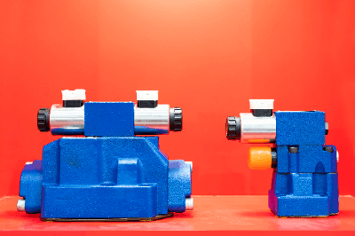
Hydraulic Solenoid Valves

A hydraulic solenoid valve is an electromechanically operated valve that controls the flow and pressure of oil in hydraulic systems. It uses electromagnetic force to open or close the valve, providing precise control over fluid dynamics in industrial and mechanical applications.

Uses of Hydraulic Solenoid Valves

These valves are integral to various industries, enabling efficient operations in:

  • Manufacturing: For controlling hydraulic presses and clamping devices in metalworking machines.
  • Construction Machinery: To operate hydraulic excavators, cranes, and lifting equipment.
  • Agriculture: In tractors and harvesters for controlling lifting arms and adjustable headers.
  • Automobiles: Within braking systems for brake pressure control and in power steering systems.

Principle of Hydraulic Solenoid Valves

The valve functions through two main components:

  • Spool: A movable cylinder inside the valve that controls oil flow by opening and closing channels.
  • Electromagnetic Coil: Generates a magnetic field to move the spool, thus controlling the flow path.

How to Select a Hydraulic Solenoid Valve

Consider the following factors for selection:

  • Supply Voltage: Match the valve’s voltage requirement with the system’s power supply.
  • Maximum Working Pressure: Ensure the valve can withstand the system’s maximum pressure to avoid damage.
  • Connection Bore: Choose a size compatible with the system’s pipes and hoses to prevent leaks.
  • Valve Type: Select between single and double solenoid valves based on the application’s needs for valve positioning and movement.
カテゴリー
category_usa

Level Staff

What Is a Level Staff?

Level Staffs

A level staff is a precision instrument in surveying and construction, designed for measuring elevation differences across various terrains. Unlike standard rulers, it features a unique scale with cubic indices for accurate reading, typically marked at 5mm intervals.

Uses of Level Staffs

Level staffs are integral to ensuring level foundations in construction and civil engineering, affecting the durability and quality of structures. They are also utilized across industries for dimensional measurements, including metalworking, quality control, education, and even DIY projects, emphasizing the importance of selecting a user-friendly level staff for specific applications.

Principle of Level Staffs

The distinctive 5mm interval memory width and cubic shape indicators are key features, allowing for accurate measurements and the ability to withstand extreme conditions. Modern level staffs are made from various materials, including wood, steel, and reinforced plastic, to suit different environments, from outdoor land surveying to chemical or heat-exposed areas.

How to Select a Level Staff

Key considerations include:

  • Measurement Accuracy and Unit Selection: Choose based on the required precision, available in millimeters or inches.
  • Measurement Range: Ensure the staff covers the necessary range, with lengths generally from 15 cm to 5 m.
  • Durability and Material: Opt for durable materials like stainless steel or aluminum, with wear-resistant markings.
  • Ease of Handling: Consider readability, ease of use, and weight for practical handling and storage.