カテゴリー
category_usa

Marking Printers

What Is a Marking Printer?

A marking printer is a printer mainly used for printing and marking in industrial applications.

They are also called label printers, tube printers, tube markers, etc. A marking printer is a printer that prints small characters to identify terminal blocks, wires, and electronic devices.

Information such as names, numbers, and symbols are printed on tubes and labels for wires, and on nameplates for terminal blocks and equipment, to enable identification. Marking printers are broadly classified into contact and non-contact, ink and laser printing methods.

Uses of Marking Printers

Marking printers are used in a wide variety of applications for marking industrial and electronic equipment, including:

  • Marking and printing of wires and tubes
  • Printing of expiration dates, lot numbers, manufacturing place symbols, barcodes, etc.
  • Marking on metal, resin, rubber products, etc.

Principles of Marking Printers

Marking printers mainly use the following principles for printing and drawing methods mainly, which consist of contact or non-contact, ink or laser marking.

1. Ink Marking

Ink-type can be broadly classified into contact-type marking method using thermal transfer ink ribbon ink and continuous or on-demand non-contact-type marking method using liquid ink.

2. Continuous Marking

A non-contact marking method is used in which ink grains continuously ejected from a nozzle are charged with a voltage corresponding to the dot position information of the print and sprayed onto the printed object with a deflecting electrode. This method is mainly used for food packages.

3. On-Demand Marking

This non-contact marking method applies pressure to the amount of ink required for marking and discharges it. Piezoelectric or instantaneous heating method is used to print by dispensing ink one drop at a time. Since it can print at high speed and at a distance, it is mainly used in manufacturing lines.

4. Laser Marking

Laser marking is an indelible marking method that uses a laser beam to dissolve, peel, oxidize, discolor, scorch, or scrape the surface of an object.

Types of Marking Printers

1. Classification by Marking

Types of marking can be broadly classified into contact-type and non-contact-type.

Contact Marking
Contact marking includes handwriting, stamping, labeling, and engraving. Handwriting is done directly by a person using a pen or similar tool. It is an inexpensive method and suitable for small-lot production.

Stamping requires an optimum amount of ink, otherwise ink dripping or, conversely, blurring of letters may occur. There are two types of stamping: hand stamping and machine stamping, which is difficult on curved or uneven surfaces.

Labels can print beautiful letters, but they require a lot of man-hours. The labels are applied to the product, but peeling can be a problem. Engraving is indelible because of the indentation on the product.

Non-contact
Non-contact marking can be done by inkjet or laser. The inkjet method prints by sending ink in a non-contact manner. It can be used on curved, soft, and fibrous surfaces. It can print on objects that are moving at high speed, making it possible to print on products that are being transported.

The laser method writes characters by scanning a laser with mirrors in the XY direction. It has major advantages such as no need for consumables such as ink, and easy maintenance. In addition, letters and dates can be easily changed.

2. Classification by Marking Printer

There are many types of marking printers in use.

Industrial Inkjet Printers
This is a typical non-contact printer. Granular ink is sprayed to print best-before dates, lot numbers, manufacturing facility symbols, etc. in dot characters. Printing is possible on paper, glass, plastic, metal, and all other materials.

Industrial Thermal Printer
Thermoelectric printers. Prints best-before dates, lot numbers, barcodes, etc. on paper boxes, cardboard boxes, plastic packaging materials, etc.

Piezo Printer
Prints product names, dates, logos, barcodes, etc. in large letters on permeable paper and cardboard boxes.

Laser Printer
Laser printers use lasers to print on PET, packaging film, printed circuit boards, DVDs, and metal caps.

Contact Rotary Printer
This printer is driven by friction between a rubber stamp and cardboard. It is inexpensive and can print semi-permanently.

Thermal Transfer Printer
Thermal transfer printer for card-shaped or roll-shaped products.

Cable ID Printer
Thermal transfer printers that print IDs on tube surfaces and name plates.

カテゴリー
category_usa

Parallel Robot

What Are Parallel Robots?

Parallel robots are industrial robots that use arms connected in parallel to perform high-speed, precise movements to a single point.

The arms are composed of parts called links and joints, and three-arm products are the most common type. Parallel robots are easy to maintain due to their simple configurations. The mechanism involves multiple motor outputs at a single point at the end of the arm, which enables high output and high precision motion.

Carbon fiber pipe/CFRP pipe is used for the arm of parallel robots. Parallel robots are utilized in pick-up operations of automated equipment.

Uses of Parallel Robots

Parallel robots are widely used in industry.

The following are examples of applications of parallel robots:

  • Stacking and arranging pallets of food products
  • Labeling cosmetics and other products
  • Picking up lightweight semiconductor parts, etc.

Because of their high speed and precision, SCARA robots are used for relatively light tasks such as sorting and picking up workpieces, including moving them. Industrial robots, other than SCARA robots, are generally expensive to install due to their high performance and often require complex maintenance work.

In many cases, they also require specialized teaching work, which requires the consideration of expensive teaching work. Parallel robots, on the other hand, have a simplified structure compared to industrial robots other than SCARA robots.

Therefore, their advantage is that they are inexpensive to install and easy to maintain and manage.

Principle of Parallel Robots

Parallel robots are simply composed of motors, bearings, and link arms. Generally, three Link-arm are connected in parallel, and each Link-arm has its own motor.

The base of the main body is fixed to the ceiling, while the tip of the arm is suspended by the link-arm. Parallel robots are characterized by their parallel link mechanism. Parallel link is a mechanism in which multiple motor outputs are concentrated at a single point at the end of the arm. Generally, articulated robots require each joint to move in turn to move the tip of the robot arm. This is the serial link mechanism.

On the other hand, in a parallel link mechanism, multiple joints are connected to the same final output destination, and each of them is operated in parallel to move the final output destination. This is called a parallel link mechanism, and it can operate at higher speeds than robots that operate with a serial link mechanism. A parallel link mechanism consists of arms, motors, and bearings. Therefore, the structure is simple and can be introduced at low-cost.

Parallel robots sold by various manufacturers are also less expensive than other articulated robots. Because they are inexpensive, they are easily accessible to those in charge of manufacturing sites. By taking advantage of their high-speed operations, operations such as pick-and-place can be automated. If multiple units are introduced in appropriate situations, it can be expected to automate multiple processes in a factory.

Other Information on Parallel Robots

Differences From SCARA Robots

SCARA robots are horizontally articulated industrial robots with three rotational axes for horizontal motion and one axis for vertical motion. Parallel robots and SCARA robots are similarly applied in transporting workpieces on a conveyor belt. The difference between these two is their horizontal operation and high speed.

SCARA robots, also known as horizontal articulated robots, are serial link robots. These robots are strong in horizontal movements relative to the ground and can perform tasks such as horizontal screw tightening and workpiece suction.

Parallel robots, on the other hand, are basically good at tasks that are vertical to the ground. In other words, it is difficult to perform tasks such as screw tightening that can be performed by SCARA robots. However, parallel robots can work faster than SCARA robots and are more efficient than SCARA robots when it comes to vertical work.

カテゴリー
category_usa

Network Scanners

What Is a Network Scanner?

A network scanner is a type of scanner that can be connected to a computer network.

Instead of connecting directly to the scanner itself, it connects to the computer via a network. This allows for easy access and operation from computers and other devices on the network.

Network scanners are used to convert paper documents into digital data. This is a great way to digitize paper documents used in daily business, such as invoices, receipts, and contracts.

This allows documents to be emailed, stored on file sharing services, or viewed on other devices.

Uses for Network Scanners

Network scanners can be used to convert paper documents into digital data. Below are some of their primary use cases:

1. Automation of Paperwork

Network scanners can dramatically streamline paperwork by automating the digitization of documents. This reduces data entry time and minimizes human error.

2. Information Sharing With Remote Locations

With a network scanner, documents and images can be digitized and immediately uploaded onto the network. This facilitates information sharing with remote team members and partners.

3. Document Backup and Archiving

Network scanners make it easy to back up and archive important documents. This reduces the risk of data loss and allows for instant retrieval of necessary information.

4. Management of Contracts and Legal Documents

Legal documents and contracts are often stored in paper form, but these can be digitized for easy retrieval and access. Some advanced network scanners also offer the ability to restrict access rights to scanned data.

5. Eco-Friendly Office

Digitizing data can significantly reduce the environmental impact associated with the creation and storage of paper-based documents.

These are only a few use cases for network scanners. With proper selection and implementation, these devices can increase productivity and efficiency in any work environment.

Principles of Network Scanners

As the name suggests, a network scanner is a scanner connected to a network, but to understand how they work, we need to consider two main elements: scanning and networking.

1. Scanning

The basic function of a scanner is to convert paper documents and images into digital data. This process typically uses a CCD (charge-coupled device) sensor to read the physical document line by line and convert that information into a digital signal. This digital signal is later reconstructed as an image that can be displayed and edited on a computer.

2. Networking

A unique element of network scanners is their ability to transmit scanned data directly to a network. This is possible when the scanner is connected directly to the network, either through an Ethernet connection or Wi-Fi.

The scanned data is sent directly to a designated network location (e.g., a server or a specific PC). It can also be uploaded directly to email or cloud storage.

Network scanners combine these two capabilities to provide the ability to digitize physical documents and instantly share that data across a network. This greatly improves the accessibility and sharing of information and increases the efficiency of the entire business process.

Other Information on Network Scanners

Network Scanner Features

The main functions of a network scanner include:

  • Digitization
    The most basic function is the conversion of physical documents and images to digital format. This allows paper-based information to be stored, edited, and shared electronically.
  • Network Connectivity
    Network scanners connect to a network via Wi-Fi or Ethernet. This allows scanned data to be sent directly to any location on the network.
  • Auto-feed and Duplex Scanning
    Many network scanners are equipped with an auto-feeder that allows them to automatically scan multiple pages at a time. Some models also have duplex scanning capability, which makes it easy to digitize documents that are printed on both sides of the page.
  • OCR (Optical Character Recognition)
    Advanced network scanners can use OCR technology to recognize text in scanned documents and convert it into editable text files. This saves significant time in creating searchable PDFs and in data entry.
  • Security
    Network scanners have security features to ensure that data is transmitted securely. These include data encryption, restricted user access, and secure network communications.
  • Cloud Integration
    Some network scanners have the ability to integrate with cloud storage services. This allows scanned data to be directly uploaded to cloud services such as Google Drive, Dropbox, and OneDrive. This not only facilitates information sharing with remote team members, but also improves data backup and accessibility.
  • Email Sending
    There is also the ability to send scanned documents directly as email. This makes sharing information faster and easier.
  • QR Code Recognition
    Some network scanners can read QR codes from scanned documents. This can help simplify automatic document categorization and data entry.

These are only some of the features offered by network scanners. Depending on your usage scenario and business requirements, you can choose a model with a variety of additional features and customization options.

A high-quality network scanner can significantly improve the accessibility and sharing of information and contribute to overall business process efficiency.

カテゴリー
category_usa

Safety Controller

What Is a Safety Controller?

Safety Controllers
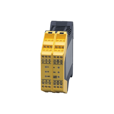
A safety controller is a device that determines whether a machine is safe to operate and controlled based on signals received from safety input devices.

It can prevent a machine from starting, or force a machine to stop if it is unsafe to do so. Safety details are obtained by the use of electronic components and software based on functional safety standards

Uses of Safety Controllers

Safety controllers are used to monitor input devices, output devices, and the safety controllers.

They receive signals from input devices while the machine is running. Examples of input devices are emergency stop pushbutton switches or light curtains. The input device outputs an ON/OFF binary signal, and depending on the state of this signal, the safety controllers send a forced stop control signal to the output device or monitor the state of the input/output device.

If a machine failure occurs, self-diagnosis detects the failure and shuts off the machine’s power by stopping the output. In the event of an abnormality, output devices can be safely stopped even if the operator is in a dangerous condition.

Principle of Safety Controllers

Hard-wired devices have been mainstream for safety reasons, but now that it is possible to configure safety circuits, electronic devices can be assured of the same quality as hard-wired devices.

The internal structure of safety controllers is designed and manufactured based on the concept of functional safety. The CPU performs mutual checks and back-checks on the input and output circuits, while the CPUs diagnose and monitor each other inside the device. Through these checks, the machine operates only when normal.

Types of Safety Controllers

Safety controllers can be classified according to whether they are programmable or not, as follows:

1. Programmable Type

Also called programmable safety controllers, these controllers allow the creation of safety control programs that are specific to the machine. Therefore, they can flexibly respond to cases in which complex logic needs to be constructed.

2. Non-programmable Type

Generally called safety relay units, these products range from those that support one pair of inputs and outputs each to those that have multiple inputs and outputs and can be used to build simple safety control circuits.

Depending on the product, safety control circuits can be easily built without programming, allowing for total and partial shutdown.

Additional Information on Safety Controllers

1. Safety Controllers Safety

To prove that a safety controller is safe, it must be based on a functional safety standard.

Functional safety standards are based on the idea that things will break, and people will fail. The measures that reduce the allowable risk are determined in relation to the scale of damage caused by failures and errors.

The level of countermeasures according to the scale of damage is called the safety integrity level. Safety Integrity Levels (SIL) are divided into four levels, with Safety Integrity Level 4 requiring the highest level of countermeasures and Safety Integrity Level 1 requiring the lowest level of countermeasures.

Based on functional safety standards, it is defined “as determining the level of countermeasures according to the magnitude of damage, and using records such as design basis and manufacturing process to explain to a third party that the countermeasures correctly reflect the level of damage.”

2. The Program Used in Safety Controllers

There are four types of safety controller programs, namely: ladder, flowchart, stepladder, and SFC (Sequential Function Chart). The ladder method is the most commonly used of the four, And it is called a ladder diagram or ladder program because its description format resembles a ladder.

A relay is an electronic component that switches ON or OFF by an external electrical signal. In a relay sequence, an input relay controlled by an external input, such as a sensor, and an output relay controlled by an external output, such as a motor, turns on or off the output relay when the conditions of a timer or counter are met.

The disadvantage of ladder programming is that it is difficult to modify the system because the programming software differs from one safety controller’s manufacturer to another.

3. Functions Required of Safety Controllers

At a minimum, the safety controller must meet functional safety standards, such as those listed below:

Investigate the Cause of a Forced Machine Shutdown
In some cases, an input device or safety controllers may determine that a machine is in danger and force it to stop, even though it is not in fact in danger. The system must be able to investigate the cause in a short period to determine if the machine was really in danger or if it was based on a malfunction.

Ease of Operation.
When a safety controller is purchased, wiring and program implementation are required. If these tasks require a lot of man-hours when starting up or reassembling a production line, production efficiency will be reduced.

カテゴリー
category_usa

Sensor Controllers

What Is a Sensor Controller?

A sensor controller is a device that applies an electric current to a sensor and outputs a control signal.

There are direct current and alternating current versions, transistor outputs and relay outputs. They receive sensor signals and output signals. Some small sensors, for example, have a built-in controller.

Since there is a wide variety of sensors themselves, it is necessary to select the controller that best suits the application. There are also panel controllers that display on a panel.

Uses of Sensor Controllers

Sensor controllers use a wide variety of sensors, such as photoelectric sensors, laser sensors, and flow sensors, each of which is connected to and controlled by a controller.

Controllers that are mutually compatible are sold as long as the standards such as current, voltage, and plug shape are matched. An increasing number of products are now available that allow multiple sensors to be controlled by a single controller. However, it should be noted that some of them may not work unless they are made by the same manufacturer as the sensors.

For example, when a sensor is used to detect the presence or absence of bottle caps in a factory, the controller receives input signals from two sensors and comprehensively determines the presence or absence, turning the output on or off.

Principle of Sensor Controllers

The controller not only supplies power to the sensors, but also has the ability to check and control the sensor values from a distance, even if the location where the sensors are installed is small.

The controller must also have a high information-processing capability to control the sensor in a short period of time and with sufficient accuracy based on the values measured by the sensor. Selection of control variables such as current, rotation speed, and position, as well as system accuracy, is important.

Sensor controllers are available with either relay or transistor contacts, and it is important to select the appropriate product for the application.

1. Relay Output

Relay output is an output method that has a mechanical contact mechanism and can be used for both DC and AC. Since the switch is turned on and off by a mechanical contact, the contact has a life span and the contact open/close response is slower than the transistor output method described below, which are disadvantages.

On the other hand, if the output unit has multiple terminals, it can handle both DC and AC, so loads with different circuit voltages, such as 200 VAC and 24 VDC, can be connected.

2. Transistor Output

Transistor output is a non-contact output type that has no mechanical contact and can handle loads from 12 VDC to 24 VDC. The disadvantage is that the current value that can be handled is 0.5A per point, which is smaller than the 2A of the relay output type. However, since there is no mechanical contact point, it has a long service life, and the contact opening/closing response is faster than the relay type.

Although only DC loads are supported, AC loads can also be driven via a relay. Basically, it compares the setting signal input from the outside with the signal sent from the sensor to control the signals so that they match and stabilize the operation.

Other Information on Sensor Controllers

1. How to Use a Sensor Controller

Sensor controllers are often used in photoelectric sensors. The greatest advantage of sensor controllers is that they can isolate the sensor portion from the output portion. Because of this feature, sensor controllers are used in the following ways:

First, it is used when the type of sensor is changed. In the past, many photoelectric sensors with 200 VAC contact switching were sold, but currently 24 VDC is the most common power supply for instrumentation. If the power supply is not available at 200 VAC when the latest model is made, the sensor controller can supply the sensor with 24 VDC voltage while sending electrical signals with 200 VAC relay contacts.

Next, it is used when increasing the number of contacts. Generally, sensors in the field have only one contact point. By using a sensor controller, multiple contact outputs can be realized while insulating the power supply between the field and the control panel. Relays can be substituted, but sensor controllers have a higher response time.

In addition, sensor controllers are often multifunctional. A timer may be installed to prevent sensor chattering, but a controller with a built-in timer can be used to save space. Some other types of sensor controllers allow the sensitivity of the sensor to be changed.

2. Sensor Controller I/O Connector

Sensor controllers may be connected to sensors with I/O connectors. Basically, the sensor has only lead wires coming out of it, which can be crimped or terminal lifted. Education and training are required to replace them, as they require the use of crimping pliers and electrical work.

By using an I/O connector for wiring to the sensor controller, the sensor can be connected with a single touch, eliminating the need for training. This not only saves time and labor in installation work, but also facilitates maintenance.

カテゴリー
category_usa

Current Generators

What Is a Current Generator?

A current generator is a device that generates a constant current for electrical measurements, such as in electronic equipment.

Many products are marketed as voltage-current generators. Since a constant current must flow continuously, the magnitude of the current is controlled by an on-board operational amplifier or reference voltage IC so that a constant current can flow even if the load resistance changes.

Some current generators can be used to measure large-scale electrical equipment by applying a large current.

Uses of Current Sensors

Current sensors are mainly used in electrical circuits. The following are examples of applications of current sensors:

1. Power Control

Current is monitored and controlled in power suppliers and power converters. In photovoltaic and wind power generation systems, current sensors monitor the amount and characteristics of the generated current to ensure a stable power supply.

They are also used to protect circuits and equipment from overcurrents. In power supply equipment and power circuits, currents exceeding the rated current can be detected by current sensors to activate protective circuits. Overcurrent protection is important to ensure safety from equipment failure due to short circuits, etc.

2. Battery Control

Used in battery management systems to monitor the charging and discharging current of batteries. By measuring the current, it is possible to evaluate the condition of the battery and estimate the remaining capacity. Battery monitoring with current sensors is important in various applications such as electric vehicles and mobile devices.

3. Motor Control

Current sensors are important devices in motor drive control. It measures the motor current and feeds it back to the control algorithm to control the torque and speed of the motor. It is widely used in drives, mainly inverters.

Principle of Current Generators

The principle of a current generator is that a negative feedback circuit using an operational amplifier and reference voltage circuit is utilized to configure a constant current generator circuit that is independent of the impedance value of the load, and the current value to be generated is determined by the reference voltage (Ref voltage) and the internal resistance value.

A circuit often used to generate a constant current is a circuit that establishes a virtual short circuit, in which 0V is generated at the input terminal of an operational amplifier in a negative feedback circuit. There are usually two types of circuits to establish a virtual short: the suction-type and the discharge-type.

1. Suction-Type

The suction-type is a method of creating a virtual short circuit by applying a current from the outside to a circuit that generates a constant current so that it is sucked into a transistor, and then using an operational amplifier and ground.

2. Discharge-Type

The discharge-type is a method of establishing a virtual short by passing current externally from the circuit of the current generator to the transistor so that it is amplified and discharged using the transistor.

In both cases, the current value is determined by the value obtained by dividing the ref voltage applied to the operational amplifier by the internal resistance, so the current value is independent of the load impedance and its value can be adjusted by the resistance.

Types of Current Sensors

Different types of current sensors exist, depending on the measurement principle. The following are examples of current sensor types.

1. Shunt Resistor Type Current Sensor

This type of current sensor measures the current value by connecting a shunt resistor in series with the circuit in which the current flows. The current flowing through the shunt resistor is calculated by the resistance value and the measured voltage drop according to Ohm’s law. The current can be measured by measuring the voltage at both ends of the shunt resistor whose resistance is known.

The shunt resistor type can measure current with high accuracy. In addition, its simple structure allows it to be manufactured at low cost. They are used on boards and in rectifier circuits for large currents.

2. Hall Effect Current Sensor

A Hall effect current sensor uses a Hall element to detect current. The Hall element is placed near a conductor through which a current flows, and a Hall voltage is generated by the magnetic field. By measuring this Hall voltage, the current is detected.

DC currents can be measured without contact. This type of sensor is used in portable clamp ammeters for DC.

3. Current Transformer Type Current Sensor

This is a current sensor that transforms and measures alternating current. It consists of a conductor that serves as the secondary winding and measures the secondary winding current, which varies according to the primary winding current. This allows the AC current to be calculated.

Because of its low cost and high measurement accuracy, it is widely used in industrial equipment. However, their heavy weight and large area for use are drawbacks.

Other Information on Current Generators

1. Current Generators and Instrumentation

Standardly used in the field of instrumentation, 4-20 mA and 1-5 V are analog signals that are widely used as output signals from sensors (transducers) or as control signals for regulators, sequencers, etc.

For example, in the case of a valve opening, the output signal from a degree of opening meter is as follows:

  • Valve opening 0%: 4mA or 1V
  • Valve opening 100%: 20mA or 5V

In other words, 4mA or 1V is output when the measured value is 0, and 20mA or 5V is output when the measured value is 100. By standardizing and unifying signals, it is possible to pass signals between instrumentation devices.

The reason for outputting 4mA when the measured value is 0 is to determine if the wire is broken. In other words, the purpose is to determine whether a 4mA current flows and indicates 0, or whether the wire is disconnected and indicates 0. The wide-angle indicator is designed to indicate 0 at 4mA and less than 0 when the wire is disconnected and no current is flowing.

2. Noise Suppression During Evaluation of Instrumentation Equipment

When signals are sent in voltage, a voltage drop occurs, causing measurement errors.

Another feature of current signals is that if the input of another instrumentation device is 1-5V, it can be easily converted to a voltage signal by inserting a 250ohm resistor. Conversely, a disadvantage is that it is easily affected by noise, which can cause errors in measurement values.

Effective noise countermeasures include the use of shielded cables, installation of noise filters, and grounding to minimize noise effects. Another point is that if a loop circuit is formed with 4-20mA signals, the entire loop will be affected if a wire is disconnected. This is because it is a series circuit. One countermeasure is to use an isolator.

カテゴリー
category_usa

Small Servo Motors

What Is a Small Servo Motor?

A small servo motor is a motor capable of high-precision positioning and speed control.

The motor has built-in speed and torque controllers, which provide feedback to the command value to achieve high-precision control. The word “servo” in servo motor is derived from the Greek word servus (slave), which includes the meaning of moving precisely in response to commands.

DC servo motors, powered by direct current, were once the primary choice, but AC servo motors, driven by alternating current, have now become the mainstream due to their superior durability and ease of maintenance. Although the term “small” is used in this article, there is no clear definition of the term.

The classification is made according to the line-up of each motor manufacturer, such as large, small, and precision.

Uses of Small Servo Motors

Small servo motors are used in production lines, measuring equipment, medical equipment, and other applications that require precise motion. Specific examples include machine tools, industrial robots, precision instruments and electronic components, liquid crystal displays, semiconductor manufacturing equipment, inspection equipment, and biological equipment.

For example, an industrial robot used in an automobile manufacturing plant can perform tasks such as picking, welding, and painting on parts repeatedly and accurately, and this is achieved through precise control by servo motors. In our daily lives, servo motors are also used in various office automation equipment and automobiles.

Principle of Small Servo Motors

Servo motors can operate accurately when combined with multiple devices. A servo motor system consists of a controller as the control tower, a driver or servo amplifier as the control unit, and a motor as the drive unit. In addition, an encoder serves as a detector to determine the actual driving status of the motor.

When a servo motor operates, the controller transmits operating conditions such as position, revolutions, torque, and speed to the driver. Based on the conditions transmitted by the driver and the motor’s rotation status transmitted by the encoder, the driver applies the optimum power to the motor for rotation, and the motor is controlled based on feedback from the encoder to achieve the target rotation conditions communicated by the controller.

In general, either a speed control system or a position control system is used when the servo controller gives commands to the driver.

Other Information on Small Servo Motors

Differences Between AC Servo Motors and DC Servo Motors

In addition to servo motors, there are various other types of motors, including DC motors, AC motors, and pulse motors. Among these, there are two types of servo motors: DC servo motors, which are DC motors, and AC servo motors, which are AC motors. AC servo motors are currently the most widely used.

AC servo motors use a permanent magnet on a rotating shaft called the rotor which is surrounded by an iron core and coils, forming a stator around the rotating shaft. The stator generates a magnetic field by passing an electric current through the stator’s coil in accordance with the timing of the frequency of the alternating current. This generates an attractive or repulsive force between the stator and the permanent magnet on the rotating shaft, causing the rotating shaft to rotate.

The rotating shaft is operated without contact with the coil, so the only frictional sliding part is the bearing. Since current flows through the stator side, it is the stator on the outside of the motor that generates heat. From the standpoint of heat dissipation, AC motors are easier to dissipate heat because the stator, which is on the outside of the motor, generates heat.

On the other hand, DC servo motors provide high torque even though they are relatively small. Another feature of DC servomotors is their controllability and low cost. However, DC motors cause brush wear because the brushes and commutator are in direct contact and conduct electricity. Maintenance is required to deal with the wear, and another disadvantage is the possibility of sparks caused by brush wear powder in some environments.

カテゴリー
category_usa

Load Switch ICs

What Is a Load Switch IC?

A load switch IC is an integrated circuit that combines the function of driving a MOSFET and FET with low on-resistance to turn the power supply on and off with the function of outputting various protection functions and abnormal conditions to the external IC.

The use of load switch ICs allows the number of components to be reduced compared to the same functionality achieved by a combination of individual electronic components, thus saving space.

Uses of Load Switch ICs

Load switch ICs are used in power supply circuits within electronic devices. Since most load switch ICs have a current rating of 0.5A to 5A, they are often used in information and communication equipment such as PCs, PC peripherals, and mobile devices rather than in industrial equipment that operates motors, solenoids, and the like.

Since they are equipped with various protection functions, they are suitable for applications that require protection of peripheral circuits and harnesses in the event of load short-circuit failure or abnormal FET heat generation, or for applications where connected devices, such as USB, can be inserted with the power on.

Principle of Load Switch ICs

1. Power Supply to Load

Load switch ICs use an internal P-channel FET or N-channel FET to turn on or off the power supply to the load. The FET drive circuit inside the load switch IC controls the gate voltage of the FET and changes the resistance between the drain and source of the FET, thereby realizing the ON/OFF function of power supply to the load.

2. Overcurrent Protection

When the current output from the load switch IC exceeds the specified value, the power supply to the load is turned off. The load switch IC can be protected when the output terminal of the load switch IC is shorted to GND or when a current flows to the load.

For example, if an overcurrent flows to the FET for load drive, the overcurrent will continue to flow to the FET if there is no overcurrent protection function. As a result, the FET may fail or the wiring may be broken. However, with overcurrent protection, the power supply to the load is turned off, so the FET will not fail or the wiring will be broken.

3. Overheat Protection

When the temperature of the semiconductor junction inside the load switch IC exceeds the specified temperature, the power supply to the load is turned off. The load switch IC can be protected when the external environment generates abnormal heat or when the load current is higher than expected.

For example, if a load fails and a larger-than-expected current flows to the FET, the FET will continue to generate heat and fail if the over-temperature protection function is not provided. On the other hand, with over-temperature protection, the power supply to the load is turned off and the FET will not fail.

4. Low-Voltage Protection

If the power supply voltage input to the load switch IC falls below a specified value, the load switch IC will be turned off. If the power supply voltage input to the load-switch IC falls below a specified level, the power supply to the load is turned off. This function prevents load malfunctions when the power supply voltage drops due to a failure of the power supply circuit.

For example, if the power supply circuit fails and the supply voltage becomes lower than the guaranteed operating voltage, the load will malfunction because the power supply to the load will continue to be ON without the low-voltage protection function. On the other hand, with the low-voltage protection function, the power supply to the load is turned off and the load will not malfunction.

Other Information on Load Switch ICs

Load-Switch IC Terminals

The typical pins of load switch IC are VCC, GND, EN, FLG, and VOUT.

  1. VCC pin
    The VCC pin is the power supply input pin of the load switch IC. The power supply line to be supplied to the load is connected to this pin, and a ceramic capacitor for bypass is connected between the VCC and GND pins. The ceramic capacitor for bypassing must be placed close to the pin to be effective.
  2. VOUT pin
    The VOUT pin is the power supply output pin and is connected to the power supply line of the load. Since the parasitic diode of the MOSFET in the load switch IC is disabled, there is no reverse current flow from VOUT to VCC.
  3. EN pin
    The EN pin is an input pin that controls the power supply output of the load-switch contact ON/OFF. Connecting the EN pin to the output port of the microcontroller allows the power supply to the load to be controlled.
    Since the logic and voltage level of the EN pin varies depending on the load switch IC, check the datasheet and connect the appropriate logic and voltage.
  4. FLG pin
    The FLG pin is an output pin that indicates the status of the load switch IC. The voltage on the FLG pin changes when the load switch IC is normal or abnormal.
    By connecting the FLG pin to the input port of the microcontroller, the state of the load switch IC can be monitored. Normally, since the FLG pin is an open drain output, connect an external pull-up resistor and leave the pin unconnected when the FLG pin is not used.
カテゴリー
category_usa

Peltier Element

What Is a Peltier Element?

Peltier Element
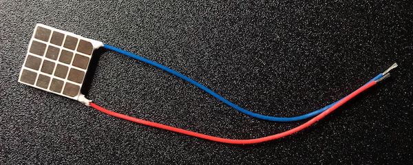
A Peltier element is a device that uses the Peltier effect, in which heat is transferred at the junction when an electric current is applied to two different metals that have been intersected.

Efficient Peltier elements currently in practical use are not made of two metals but of three different materials: an n-type semiconductor, a metal, and a p-type semiconductor. They are usually used as cooling devices by utilizing heat transfer, but can also be used as heating devices since changing the direction of the electric current also changes the direction of heat transfer.

Unlike heat pumps, the Peltier element has the advantage of generating no noise or vibration, since the cooling effect is achieved simply by applying an electric current. In addition, since no refrigerant is required and no corrosive liquid is used, the Peltier element is a cooling device with low environmental impact.

Uses of Peltier Elements

Peltier elements are used in a wide range of fields as clean cooling elements.

1. Food Industry

Peltier elements are compact, clean, and safe. They are used in food showcases, small drink cases, milk coolers, hotel pans, etc.

2. Industrial Field

Industrial equipment is vulnerable to water without exception, but measures are taken to control temperature and supply cold air with minimal condensation, or to incorporate condensation drains. Applications include operation panel cooling, surveillance camera cooling, local cooling of internal control panel components, cooling of molding dies, and constant-temperature humidity air supply systems.

3. Optical Field

Peltier elements are often used to cool devices in limited space. Specifically, they are used for direct cooling of heat-generating sources, cooling of small relay boxes, temperature control of photodetectors, temperature control of laser diodes, cooling of CCD cameras, projectors, copiers, and surveillance cameras, and cooling water for lasers, etc.

4. Consumer Field

Peltier is used in commercial refrigerators for hospitals and hotel guest rooms, taking advantage of its advantages of no vibration and noise and the small size of the cooling mechanism. Peltier refrigerators are used in small refrigerators, cooler boxes, beer servers, wine cellars, aquarium water temperature control, computer CPU cooling, dehumidifiers, air purifiers, hair dryers, negative ion generators for facial care equipment, etc.

5. Other Fields

Peltier elements are also used for cooling and heating in the fields of measurement and analysis, semiconductors, and medical and physical chemistry.

Principle of Peltier Elements

Peltier elements currently use p-type and n-type semiconductors instead of metals. For electrons to be transferred from a p-type semiconductor with a low energy level to an n-type semiconductor with a high energy level, it is necessary to take in energy from the outside, which causes heat absorption and a decrease in temperature.

If the direction of the current flow is reversed, electrons are transferred from the higher energy to the lower energy side, resulting in heat generation to release the excess energy. Therefore, Peltier elements can be used as either a cooling or a heating device, depending on the direction of the current flow.

However, heat conversion using Peltier elements is not suitable for very large-scale cooling or heating because the efficiency is not high for power consumption. For efficient cooling, it is effective to use Peltier elements in combination with heat dissipation and exhaust mechanisms using fins and fans.

Other Information on Peltier Elements

1. Advantages of Electronic Cooling

Generally, a cooling system exchanges heat by using a cooling gas called a refrigerant. Since this refrigerant is one of the greenhouse gases that affect global warming in no small measure, its environmental impact cannot be ignored.

On the other hand, electronic cooling using Peltier elements is a cooling system with a low environmental impact because it does not require a refrigerant. In addition, cooling systems that use refrigerants require compressors, which inevitably generate noise and vibration, but electronic cooling does not have these concerns.

2. Cooling Function of Bertsche Element

The cooling function can be realized by utilizing the characteristics of the Peltier elements. When a DC current is applied to Peltier elements, heat absorption occurs at the low-temperature side, and heat generation occurs at the high-temperature side. The cooling function of the Peltier elements is based on this phenomenon.

Commercially available ones are capable of cooling down to negative temperatures. They are used in cooling boxes, cooling CPUs in PCs, etc.

3. Application to Wearable Devices

Wearable devices have been developed using the properties of Peltier elements. Among the wearable devices on the market are devices that can heat or cool the neck.

This device can feel warm or cold by controlling the temperature of a panel located where it touches the neck.

カテゴリー
category_usa

Prober

What Is a Prober?

Prober
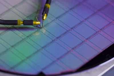
A prober is a device for fixing a probe (needle) at an arbitrary position, also called a probe station. It is a positioning device that connects the probe of the contact part of the measurement device to the correct position of the electrode of the semiconductor to measure electrical items on the semiconductor wafer in the front-end process, mainly in the semiconductor wafer manufacturing process and IC design and development.

Since the electrode area of a semiconductor is tiny, it is necessary to apply the probe of the contact part of the inspection device to the exact position. Very precise controllability is required for the prober in positioning.

In addition to semiconductor chips, this equipment is often used to evaluate the electrical characteristics of PCB substrates, various thin-film substrates, such as sensors and filters, and ceramic substrate packages, such as LTCC.

Uses of Probers

Probers are used when inspecting the electrical characteristics of semiconductors, thin-film substrates, and package substrates. When used for research and development purposes, the probers should have functions to eliminate noise and prevent signal leakage (crosstalk), be able to measure with high accuracy and be as versatile and flexible as possible in terms of measurement methods.

For mass production, the most important feature is the ability to perform fast processing accurately and in large quantities, so a wide variety of probers models should be selected to suit the application.

The probers must also be temperature tolerant to ensure correct operation at high and low temperatures during temperature characteristic evaluation. In addition, a prober that can handle high voltage and low impedance is required when used to measure semiconductors for power devices.

Principle of Probers

The most typical prober for silicon wafer applications is described below. The prober consists of a wafer chuck for fixing a silicon wafer, a stage for moving the wafer chuck in the XY direction, a contact plate to which multiple probes for inspection are attached and which moves in the Z direction concerning the stage, and a camera for positioning. The wafer is then moved in the XY direction to the stage.

In addition to these mechanisms, a transport system for moving silicon wafers is often included in probers products. The principle of operation is that when a silicon wafer is set, the silicon wafer is transported to the wafer check position and fixed.

The stage then positions the wafer in the XY direction, and with the position of the probe for measurement and the electrode of the semiconductor on the silicon wafer adjusted, the contact plate moves in the Z direction to contact the probe and the electrode. Through this process, the electrical characteristics of the semiconductor can be inspected by the inspection system.

Other Information About Probers

1. Miniaturization of Semiconductor Devices and Requirements for Probers

With the recent miniaturization of semiconductor devices, microcurrent measurement is an important indicator to evaluate the manufacturing quality of semiconductor devices. In the design and fabrication of semiconductor devices, changes in device materials, crystal growth parameters, or geometry can create unexpected current paths inside the device, which is commonly referred to as leakage current.

Increased leakage current can be caused by lattice defects, gate oxide structure, substrate selection, and other factors that can induce excessive power consumption and, in some cases, lower breakdown voltage. In recent years, the gate length of FETs and the emitter size of bipolar transistors in semiconductor devices have become very small, and while the voltage required to drive these devices is decreasing, leakage current is increasing.

Therefore, from the viewpoint of quality evaluation, highly accurate current measurements using probers are required. One measure to improve the accuracy is the development of cryogenic probes.

2. Positioning Accuracy of Probers and Positioners

The contact position accuracy of the probers directly affects the measurement accuracy. If various evaluations are performed without correct probing, it is difficult to know what is being evaluated.

For example, if you want to evaluate the characteristics of a semiconductor device, but the wafer is out of position and probed on an insulator, it is not difficult to imagine that the evaluation results will be far off from the expected results.

It is necessary to understand the accuracy required for the evaluation target and then focus on improving that accuracy. It is the component called a positioner (manipulator) that determines the positioning accuracy of the probers. Positioning accuracy varies depending on the correct selection of a positioner suited to the required specifications.

The specifications of a positioner are almost always determined by the following four factors: (1) travel distance, (2) travel resolution, (3) adjustment sensitivity, and (4) external dimensions. See below for the contents of each specification.

  1. Travel Amount
    This is the amount of movement in the XYZ direction. Usually, it is described in the order of mm.
  2. Travel Resolution
    It is defined as the amount of movement per revolution.
  3. Adjustment Sensitivity
    Defined in terms of the minimum adjustable distance. In most cases, it is defined in μm.
  4. External Dimensions
    This is the size of the positioner, the will price increase in proportion to the size.

3. High-Frequency-Compatible Probers

Probers suitable for RF evaluation are required for the evaluation of semiconductor transistors for high-frequency (RF) and device modeling.

Generally, a GSG probe (a needle with a ground (GND) on both sides of the signal pad) with a dedicated calibration board is used, but depending on the frequency to be measured, care must be taken not only with the probe but also with the RF cable to the network analyzer or various measurement devices. This is because the flexure of the cable may affect the RF measurement results.

In the millimeter wave band, which has a higher frequency than a microwave, a dedicated VNA extender is used, but the configuration of the device should be discussed in detail with the dedicated manufacturer because the probers configuration itself has a very large impact on the measurement.