カテゴリー
category_usa

Air Clamp

What Is an Air Clamp?

エアクランプ

Air Clamps are clamps that operate using compressed air.

A clamp is a device that holds an object in place by pressing down on it. It is possible to press down with more force than manual operation. Widely used in factories, it is one of the indispensable tools for processing materials such as metal products and wood.

Since they do not use electricity, they reduce the risk of fire or electric shock at the work site. However, proper maintenance is required, and regular lubrication keeps the clamps running smoothly and extends their service life. It is also important to set the air pressure appropriately, as excessive air pressure can cause damage to clamps and work pieces.

Uses of Air Clamps

Air Clamps are widely used in factories. The following are the main applications of Air Clamps:

1. Metal Processing

Air clamps are used for cutting metal plates and pipes in metal processing. They are also indispensable tools in processes such as welding and bolting. Air Clamps are capable of high torque and force, allowing work to be performed with a high degree of precision.

2. Woodworking

Air clamps are used for cutting and drilling in woodworking. They are also used for gluing wood. They can hold wood firmly, which improves the accuracy of work.

3. Automobile Maintenance

In automotive maintenance, air clamps are used to replace or adjust engine parts and change tires. The high torque of Air Clamps firmly holds heavy automotive parts.

4. Painting

Air clamps are sometimes used to secure spray guns in painting applications. Spray guns secured by Air Clamps are less likely to shake, thus ensuring a uniform coating.

Principle of Air Clamp

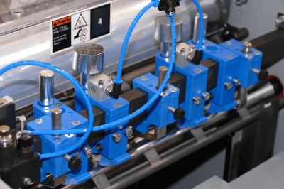
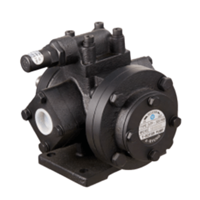
Air Clamp is a type of toggle clamp that uses compressed air as its power source to hold an object in place. The source of compressed air is generally a device such as an air compressor. The compressed air is sent to the Air Clamp through an air line.

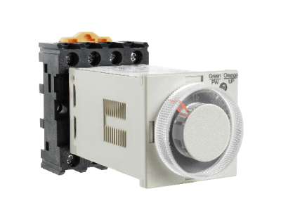
Inside the Air Clamp is a cylinder that opens and closes the clamp. The cylinder can close the clamp by pushing up the piston as compressed air flows in, and open the clamp when air is removed from the cylinder. The operation is generally controlled by a solenoid valve, which is operated by sending commands to the solenoid valve through button operation or a foot pedal.

A toggle mechanism is often used for the clamping part. The toggle mechanism is a type of link mechanism consisting of two links and a slider.

Types of Air Clamps

Air Clamps are widely used in various industries. The following are examples of Air Clamp types:

1. Integrated Air Clamp

Integrated Air Clamps are air clamps with the clamp and cylinder integrated into one unit. They feature a compact design and can be used in any installation location. Another advantage is that they are easy to install. 

2. Parallel Gripper

This clamp is made of multiple arms. The arms move in parallel with each other to firmly grip an object. This type of clamp is particularly effective when handling large items.

3. Rotary Clamp

This clamp can process an object while rotating it. Since the clamp can be rotated while holding the workpiece in place, work efficiency is greatly improved.

How to Select an Air Clamp

Air Clamps are useful tools that greatly improve work efficiency, but there are a few important points to keep in mind when selecting the right Air Clamp.

1. Intended Use

Select the appropriate size and force for your application. Larger Air Clamps with greater force are suitable for handling large parts, whereas smaller Air Clamps are better suited for handling smaller parts.

2. Shape

Various shapes are available, including straight and angled types, and mounting methods such as base mounting and flange mounting can be selected. It is important to select the appropriate shape and mounting method according to the work to be performed and the installation location.

3. Clamping Speed and Repeatability

Clamping speed and repeatability are also important factors that greatly affect work efficiency. A high clamping speed is required when performing a large number of operations in a short time. High repeatability is also important for precision work.

カテゴリー
category_usa

Analog Timer

What Is an Analog Timer?

Analog Timers

An analog timer (time relay) is a device that turns a contact on or off after a certain set time from the time it receives an input.

Analog timers offer the advantage of easily adjusting the set time using a dial. However, on the other hand, there is a risk of error associated with their analog nature. Analog Timers can not only switch ON/OFF only once, but can also turn ON/OFF periodically or change the input/output values, such as turning the output ON or OFF upon receiving an ON input.

Uses of Analog Timers

Analog Timers can be used to run a device or stop a device after a certain amount of time has elapsed. Analog Timers are classified according to several modes of operation and should be selected according to when you want to switch the output.

1. Pedestrian Push-Button Signals

After pressing the button, the traffic light switches from red to blue.

2. Automatic Doors

When a person approaches a door, a sensor triggered and the door opens. After a certain period, when the person leaves the door, the door closes.

3. Cuckoo Clock

At a predetermined time, the gimmick operates and the pigeon inside repeatedly unfolds and retracts.

4. Coin-Operated Dryer

When money is inserted, the dryer operates for a predetermined time.

Principle of Analog Timer

Analog Timer consists of four parts: a clock part, a power supply part, an input part, and an output part. In the case of the power start method, the Analog Timer is activated after voltage is applied to the power supply section.

The input part receives an input signal from the outside, the clock part measures the time, and when the set time is reached, the output part sends out an output signal to the outside. The user can set the set time as desired. When the set time is reached, it is called time-up.

There are several types of operation modes for the Analog Timer:

  • ON-delay operation
    Output turns ON with a time delay after input ON.
  • Off-delay operation
    Output turns OFF with a time delay after input OFF.
  • Flicker Operation
    Output turns ON/OFF periodically by time difference after input ON.
  • Interval Operation
    Output is turned off by time difference after input ON.
  • Star-delta operation
    For electric motors.

ON/OFF switching is performed by switching contacts. The fifth type, known as “star-delta operation,” is difficult to visualize solely from its name. Therefore, we will provide a brief introduction here. “Star” and “delta” are named after the circuit shape of an electric motor’s windings, and the timer is controlled by turning the star/delta contacts ON and OFF.

How to Select an Analog Timer

1. Display Accuracy

The degree to which a unit of measure is to be displayed on a timer should be determined according to the application. For example, if you are measuring cooking time, you do not need to measure in tenths of seconds; seconds are sufficient. On the other hand, if the timer is to be used for industrial purposes or experiments, it must be able to measure in tenths of seconds.

2. Measurement Range

The measurement range of the timer must be confirmed. If you need to measure for a long period of time, you need to select a timer that can measure for a long period of time. Depending on the timer, for example, a day may be counted after 24 hours, or 25:00, 26:00, and so on.

3. Ease of Operation

Ease of use is important, including button placement and digital display. In particular, the placement of the buttons can lead to timing discrepancies between ON and OFF. Therefore, it is necessary to try several times when selecting a timer. The displayed numbers should also be in a font that is easy to read and understand.

4. Durability

For long-term use, it is important to select a durable product. Rugged and durable timers are needed, especially for industrial applications and outdoor use. Since cold or heat may degrade the functionality of the product, check in advance “where it will be used” and how it will be affected in that location.

5. Price

Select a timer that fits your budget. It is important to select a cost-effective product that has the necessary functions but eliminates unnecessary features. Even with the same functions, there are minor differences in durability and materials, so care should be taken when comparing multiple timers.

6. Reviews and Evaluations

Before purchasing, it is a good idea to check reviews and evaluations by other users. By referring to the opinions and evaluations of people who have actually used the timer, it will be easier to find the right timer for you. It is recommended that you check the opinions of users who have purchased the product for the same purpose as you.

カテゴリー
category_usa

Trochoid Pump

What Is a Trochoid Pump?

Trochoid Pumps

A trochoid pump is an internally inscribed positive displacement pump that transports fluid by meshing an external gear with an internal gear. It is a registered trademark of Japan Oil Pump Co.

It is called a trochoid pump because the tooth profile of the external and internal gears is shaped like a trochoid curve. A trochoid curve is a curve drawn by a fixed point inside or outside a circle when the circle is rolled without sliding along a certain curve.

When an internal gear is driven, the meshing external gear also rotates in the same direction. This makes them compact, and they have features such as low-gear sliding speed, low noise, and low-pressure pulsation. Although trochoidal pumps are most commonly used for pumping oil, they can also be used for coolants, fuels, and special liquids.

Uses of Trochoid Pumps

Trochoid pumps are mainly used to supply lubricating oil in construction and industrial equipment, machine tools, food machinery, printing machinery, environmental facilities, leisure facilities, and ships. Liquids to be transported include hydraulic systems, abrasive oils, fuels, coolants, and chemicals, other than volatile oils and gasoline.

When selecting trochoid pumps, the operating pressure, speed, discharge rate, temperature, and type of liquid being conveyed should be considered.

Principle of Trochoid Pumps

Trochoid pumps consist of a circular casing with two gears whose tooth profile is a trochoid curve, a shaft, a bearing, a suction port, a discharge port, a shaft seal, a relief valve, and a suction strainer.

There are two types of gear, one that fits into the inner circular casing and the other that fits inside the outer gear. The number of teeth in the inner gear is one less than in the outer gear, and both gears are eccentric. A shaft is connected to the center of the inner gear to rotate it.

When the inner gear rotates, the outer gear, which is meshed with the inner gear, also rotates, but the outer gear rotates slower than the speed of the inner gear. The volume of the space separated by the two gears then changes. This change in volume causes the fluid to be sucked in at the suction port and discharged at the discharge port, thus functioning as a pump.

Trochoid pumps are pumps with a constant discharge rate. When the rotation speed is constant, the relationship between the discharge volume and pressure is inversely proportional, and the discharge volume is maximum when the pressure is zero. When the pressure is at maximum, the discharge volume is zero, but the drive power is at maximum, which may cause the electric motor to overload.

Other Information About Trochoid Pumps

1. Characteristics of Trochoid Pumps

Trochoid pumps have four characteristics:

  • Compactness
    Because it is an internally geared pump, it is smaller than other pumps of the same capacity. Therefore, it allows for greater freedom in equipment design.
  • Self-priming
    Because it is a positive displacement pump and self-priming, unlike other centrifugal pumps, it has the advantage of not requiring priming oil.
  • Low Noise and Low Pressure Pulsation
    The internal gears have low sliding velocity, resulting in low meshing noise and low-pressure pulsation.
  • Low Cost
    The simple structure allows the inner and outer gears to be manufactured with sintered alloys, making them relatively inexpensive.

2. Failure of Trochoid Pumps

Clogging of the suction piping or strainer can cause problems such as failure to raise the discharge pressure. The filter on the suction side should be inspected and cleaned. There is also a possibility that air cannot be suctioned and discharged due to pinholes in the line or improper tightening at the flange.

Furthermore, when the machine is restarted after a long shutdown, the viscosity of the liquid may have increased or it may be sticking. Failures that cause liquid leakage are most likely due to deterioration or damage to the sealing parts. It is important to perform preventive maintenance by deciding on a maintenance cycle, such as periodically replacing oil seals and other consumable parts.

There is also a possibility of one-sided tightening for leakage at the flange surface. When cavitation occurs in the pump, abnormal noise is generated. If cavitation is occurring, the suction pressure of the pump should be measured and the loss or resistance on the suction piping side should be lowered as much as possible.

If the liquid is near the saturation vapor pressure of the liquid due to outside temperature, it may flush. If the bearing part is damaged, the bearing must be replaced. It is important to perform maintenance to replace them periodically as consumable parts.

カテゴリー
category_usa

Earth Leakage Relay

What Is an Earth Leakage Relay?

Earth Leakage Relays
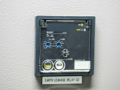
An earth leakage relay is a mechanical device used to detect the presence of leakage current in an electrical circuit.

They are also called ground fault relays. Electric circuits are generally insulated from the surrounding environment by insulating resins such as polyethylene or vinyl.

When a part of an electric circuit comes into contact with a conductive object due to damage to the insulation and electricity flows, this is called leakage current. Accidentally touching a leaky electric circuit or surrounding metal can cause an electric shock to the human body, resulting in personal injury. If electricity travels through the steel frame of a building, it can also cause a fire, so care must be taken.

The use of earth leakage relays to cut off the power supply or to issue an alarm prevents the above phenomena.

Uses of Earth Leakage Relays

Earth leakage relays are used in many electrical circuits. The following are examples of applications of earth leakage relays:

1. Ground-Fault Circuit Breakers

RCDs are devices that automatically shut off the power supply when a leakage is detected. RCDs are generally used in low-voltage circuits and are also installed inside distribution boards for home use. 

2. Inside a Cubicle

A cubicle is an enclosure for power supply and demand with a high-voltage transformer and circuit breaker built inside, and is used in supermarkets and public facilities. Inside the cubicle, leakage current fire alarms and other devices are built in to detect leakage currents at an early stage. 

3. For Controlling Gas-Insulated Switchgear (GIS) And Vacuum Circuit Breakers in Substations

Substations handle electricity at voltages higher than high voltage, so vacuum circuit breakers are used to energize and disconnect the electricity. Since these devices do not have a function to detect leakage current, they are controlled by a combination of Earth Leakage Relays.

Principle of Earth Leakage Relay

There are several principles by which earth leakage relays can detect leakage current.

1. In the Case of Direct Current

When DC voltage is the target, there is a method of detecting the voltage to ground. Generally, the middle point between the two terminals of a DC circuit is 0 V to ground, but when a leakage current occurs, the ground-faulted wiring terminal side becomes 0 V to ground. Therefore, leakage current can be detected by measuring the ground voltage at both terminals. 

2. In the Case of Alternating Current

In the case of alternating current, it can also be detected by measuring the reciprocating current. In general, the sum of the reciprocating currents in an electric circuit is equal, but when a ground fault occurs and a current flows between the two terminals, the sum of the reciprocating currents is not equal. Therefore, leakage current can be detected by measuring the round-trip current and checking if it is balanced. 

3. Zero-Phase Current

There are other methods to measure zero-phase current. Magnetic fields are always generated around cables carrying alternating current, but they are characterized by the fact that they cancel each other outward and inward.

When a ground fault occurs, one of the magnetic fields becomes stronger than the other, so they can no longer completely cancel each other out, resulting in a zero-phase current due to the magnetic field. By checking this zero-phase current, leakage current can be detected.

Types of Earth Leakage Relays

There are two main types of earth leakage relays: non-directional and directional. Both types of relays use a zero-phase current transformer to measure the zero-phase current to determine if there is a leakage current and send a leakage current signal to the circuit.

1. Non-Directional Earth Leakage Relay

This is a mechanism to detect the accident current in case of leakage current by a zero-phase current transformer. It is also called a ground relay.

Currents in a three-phase AC circuit are divided into three types: positive-phase current flowing in the positive direction on each line, reverse-phase current flowing in the reverse direction, and zero-phase current flowing in the same phase. Since zero-phase current flows in the case of leakage current, leakage current can be checked with a zero-phase current transformer.

The non-directional type only checks for ground faults, so there is a risk of malfunction if a ground fault occurs in the upper system, etc.

2. Directional Earth Leakage Relay

This system detects the fault current in the event of a ground fault by means of a zero-phase current transformer and a zero-phase voltage detector. It is also called a directional ground relay.

A zero-phase voltage detector is a device that detects zero-phase voltage by means of a capacitor inside the device. The zero-phase voltage is normally 0 V, but a voltage is generated in the event of a ground fault.

This voltage is divided by a series-connected square-phase capacitor and a detection capacitor, and the voltage across the detection capacitor is further reduced by a transformer. The earth fault direction relay detects the direction of the earth fault. Therefore, it does not malfunction when a ground fault occurs in the upper system, but only interrupts the ground fault that occurs in its own system.

カテゴリー
category_usa

Floating Connector

What Is a Floating Connector?

A floating connector is a generic term for connectors that are used to connect electronic circuit boards and are equipped with a mechanism to adjust for small relative connection errors between boards.

Uses of Floating Connectors

Floating connectors are almost always used in situations where boards are connected by robots because they allow for mounting positional errors between boards.

Floating connectors are also useful in situations where stress on the device needs to be reduced because they not only increase the degree of freedom of board connection but also allow the release of stress between boards after connection.

For example, it is often used in situations where multiple boards are connected to each other, or where both boards are rigidly installed on the baseboard and there is no two-dimensional degree of freedom.

Principle of Floating Connectors

Connectors have an insulator, which is a part that can transmit electronic information by bonding to each other, on top of the base substrate.

The role of the connector is to join two boards through this insulator.

Now, the size of these connectors has been getting smaller year by year with the advancement of technology, and now there are multiple insulators in a row with a high density of about 0.5mm pitch between adjacent boards. When joining these insulators, it is necessary to design the misalignment between each insulator to be less than the tolerance, but this requires very high technology.

Therefore, to express the degree of freedom in the three-dimensional mounting tolerance of insulators, floating connectors use springs to make the insulators look as if they are floating in midair.

As a result, even when strain exists at the time of connection between boards, the spring part can move to absorb the error caused by its misalignment.

Even if there is no misalignment at the time of connection, the misalignment will be caused by the tolerance of the screw holes when the boards are subsequently screwed together for installation on the main board.

Floating connectors can absorb the stress-strain caused by this indirect misalignment due to their structure.

カテゴリー
category_usa

Area Sensor

What Is an Area Sensor?

Area SensorsAn area sensor is a sensor that detects people or objects within a predefined area.

It detects objects by emitting light or sound waves and detecting their reflection or transmission. Safety light curtains are one type of area sensor.

In recent years, sensors that detect not only two-dimensional surfaces but also three-dimensional spaces have become available.

Uses of Area Sensors

Area sensors are used for industrial or security purposes. The following are examples of applications of area sensors:

1. Intrusion Detection in Factory Equipment

Industrial equipment includes many facilities that operate under pressure and torque that can easily destroy the human body. Presses for industrial waste disposal and conveyor belts for transporting coal fuel are examples. If workers or passersby inadvertently come into proximity to such equipment, there is a risk of personal injury.

It is common practice to surround these facilities with perforated metal or handrails to prevent easy contact, but it is inconvenient to cover areas completely where people frequently enter and leave the facility or where periodic maintenance is required. In such locations, area sensors are installed so that equipment will be shut down when a person enters. Area sensors used for such safety purposes are also called safety light curtains. 

2. For Object Detection in Unmanned Vehicles

In factories and automated warehouses, AGVs (Automated Guided Vehicles) are used to transport goods automatically in order to save labor and reduce costs, and area sensors are often used to detect objects in the direction the AGV is traveling and in the surrounding area. area sensors, such as those used in AGVs are also called Safety Light Scanners. 

3. Human Detection

Sensors are sometimes used to detect people in order to open and close automatic doors or to turn on gate lights. Sensors that detect people are specifically called human detection sensors.

They may also be used to detect unauthorized intruders at night for security purposes. Attached to a security camera, it zooms in or triggers an alarm when it detects a person. Often sold as a security sensor light in combination with lighting fixtures.

Principle of Area Sensors

Area sensors use infrared, ultrasonic, or visible light as the detection medium.

1. Infrared Light

Infrared light is light with a longer wavelength than visible light. Since it is invisible and does not damage the landscape, it is a widely used detection medium in applications ranging from general security equipment to industrial applications. Generally, detection is performed using light with wavelengths of 1 to 1,000 μm.

Infrared rays have the characteristic of being emitted spontaneously from objects that are warmer than the outside air. This characteristic makes it ideal for detecting human bodies with body heat, and it is used for gate lights and security lighting. In addition, a detection method based on the difference in sensed temperature may be used to open and close faucets, and a mechanism that converts the temperature difference into an electrical signal after detecting the temperature difference within the detection area is used.

2. Ultrasonic Waves

Sound waves with wavelengths shorter than the human audible range are called ultrasonic waves. Ultrasonic waves are sometimes used in area sensors because they are inaudible to the human ear and can detect surrounding objects by their reflected velocity. A sensor that uses ultrasonic waves to detect objects is also called an ultrasonic sensor.

After measuring the time it takes for sound to be reflected back, it is converted into an electrical signal to detect the distance to the object.

3. Visible Light

Sensors that detect objects by visible light are called photoelectric sensors. Area sensors using the same principle as photoelectric sensors are also available. They consist of a light emitting part and a light receiving part. The light receiving part detects when the light emitted is intercepted or reflected, thereby detecting an object.

Types of Area Sensors

The following types of area sensors exist due to differences in the above-mentioned principles. 

1. Light Curtains and Safety Light Curtains

Products that use multiple photoelectric sensors side-by-side to detect flat surfaces are called light curtains, while products that are specifically designed for safety measures are called safety light curtains. In general, this type of product is often referred to as an Area Sensor. 

2. Infrared Sensor / Human Detection Sensor

These sensors detect infrared rays and are often used to detect people. They are intended for crime prevention and safety.

3. Laser Scanner

A laser scanner is a sensor that detects surrounding objects by transmitting light rays in a fan shape. A wide area centered on the sensor can be detected in three dimensions. Laser scanners used especially for safety applications are called safety laser scanners.

In recent years, due to its wide detection range, it has been actively developed as an in-vehicle sensor.

Extruder

What is an Extruder?

An extruder is a piece of equipment that produces molded products such as tubes and sheets by heating the input material to soften it and extruding it with the screw of a cylinder.

From pellets or minced raw materials, they are processed into various shapes, such as round or square pipes, tubes, ducts, and sheets, depending on the shape of the die. Since raw materials are fed sequentially from the hopper, continuous production is possible. This is useful for mass production.

In extrusion molding, the shape is given by the die and then hardened by cooling processes such as water cooling and air cooling to maintain the shape. When the material is sufficiently hardened, it is taken back and cut to make the product. Extrusion has a long history and has a wide range of applications, from food processing to metal and plastic molding.

Uses of Extruders

Extruders are used to process metals, such as aluminum and copper, and thermoplastic materials into molded products by heating and melting them and then giving them shape through a die. Taking the production of synthetic fibers from plastic as an example, strands of plastic are obtained by drawing the molten plastic obtained from the extruder’s outlet as it is cooled and stretched.

Extruders can also be used for continuous production of foams. The molten plastic is melted by pressurizing a foaming agent into the molten plastic. As the foaming agent is pushed out of the die outlet to normal pressure, the pressure difference causes the foaming agent to be released, resulting in a foam body.

Besides the industrial field, another application of extruders is the processing of food products such as sausages, pasta and beef noodles, and pet food. Extruders can add steam to heat the food, reducing microorganisms in the food and simultaneously sizing the starch.

Principle of Extruders

The role of extruders appears to be a simple one: to give shape to dissolved raw materials. However, to produce a stable product, it is important to optimize the conditions at each location according to the raw material and target shape.

First, the raw material fed into the hopper is adjusted to a constant speed using a weight feeder or other means to prevent clogging, and then the cylinder is filled with the raw material. A heater in the cylinder heats the material to soften it, and the speed of the screw is adjusted to extrude the material while applying the appropriate pressure to obtain the desired shape, such as a tube or bar shape.

The extrudate is cooled enough to retain its shape in a cooling unit before being taken back and cut. The key is temperature control at each stage of the process. If the temperature of the extruded material is too high, the shape given at the die exit may not be retained because of the high viscosity and the time required for cooling.

Also, if the cooling process is too fast, the molded product will be distorted, which may cause rupture. In addition to heating from the heater, extruder heating also generates frictional heat between the screw and the material or between materials.

Therefore, temperature oscillation (hunting) will occur even when the machine monitors the set and actual temperatures and adjusts them automatically.

Types of Extruders

Extruders are classified by the extruders’ construction, die configuration, and post-processing methods. Extruders can also be classified by the number of screws into single-screw and multi-screw.

When multiple raw materials are used, not only melting but also uniform mixing is required, so multi-axis extruders with high mixing performance are often used. The configuration and direction of the rotation of the screw must be determined according to the raw material.

The shape of the molded product of the raw material is largely determined by the shape of the mouthpiece, called the die, of the extruders. Therefore, the types of extrusion molding are often called according to the shape of this die and the subsequent process. Typical moldings include tubular, bar, and sheet shapes.

In addition to standard shapes, complex shapes, and multi-layered moldings can also be obtained. Extruded foam products can also be produced by adding a blowing agent.

カテゴリー
category_usa

Soldering Robot

What is a Soldering Robot?

A soldering robot is a device in which a soldering iron is attached to a robot for automatic soldering.

As it uses a robot arm, etc., a soldering robot can solder in a narrower space than conventional soldering automation devices such as mounting mounters and soldering machines. In the past, soldering in tight spaces could only be done manually by humans.

Uses for Soldering Robots

Soldering robots are used for soldering, but they are better suited for manufacturing small quantities of a wide variety of products rather than mass-produced items. They are also good at soldering to parts with localized solder or low heat resistance temperatures, and other detailed and precise work that is conventionally done manually by human operators. However, this makes the process more time-consuming than other automated soldering equipment.

For example, the soldering of the amplifier board of the Smart Fiber Sensor is done by the slide soldering method with the introduction of soldering robots. The robot is in charge of soldering in precise areas with a land width of 0.5 mm and a pitch of 1 mm, thereby improving work efficiency.

Principle of Soldering Robots

Soldering robots consist of a robot with an arm, a soldering iron, a controller, and a teaching pendant that sets the conditions. Some robots are equipped with a nitrogen gas generator to prevent oxidation of the soldering iron tip and solder surface.

Robot types include small tabletop robots, as well as SCARA and Cartesian robots, depending on the style of the robot arm. They can be used by inputting soldering conditions from a teaching pendant and having them perform the prescribed soldering.

Types of Soldering Robots

Soldering robots include tabletop robots, SCARA robots, and Cartesian Coordinate Robots. In addition, they are classified according to the soldering method. The most common soldering methods are the soldering iron method and the laser method. The soldering iron method is still widely used today.

1. Soldering Iron Method

In the soldering iron method, the soldering iron is heated to nearly 350°C, and solder is poured from the tip of the iron to join the metal. Compared to the reflow soldering method, in which cream solder is applied and then heated to melt the solder, the iron method does not apply heat directly to the electronic components. Therefore, it is possible to perform high-quality soldering with minimal thermal damage.

2. Laser Soldering Method

In the laser process, the solder is melted by a laser beam. This method uses the fact that a laser beam can be focused by a lens or mirror to form a high-density beam that heats an object to a high temperature. Components and solder are placed in the area where the laser beam hits the object, and the solder is soldered. This laser method is suitable for narrow and fine processing because of its non-contact soldering.

Other information about Soldering Robots

1. Advantages of using Soldering Robots

The advantages of using soldering robots are the increased automation, speed, and accuracy of the soldering process. Good soldering depends on the temperature of the soldering iron, contact time to the board, contact area, and other factors.

If these factors are not properly controlled, the soldering iron may be too low in temperature or too short of contact time, which can cause the solder to flake. Solder flux will result in a weak and brittle bond. The same is true for burnt solder, which is caused by insufficient heat conduction. This situation is especially likely to occur at work sites where there are many inexperienced novice workers, which increases the defective product rate and lowers production efficiency.

In such cases, it is effective to introduce soldering robots to the shop floor and have them perform the same tasks as experienced workers. Most soldering robots are capable of positioning control in 0.1 mm increments and have high positional repeatability (work accuracy). In addition, motor-driven robots can operate at high speeds, which means they can work faster than humans and avoid human error due to fatigue.

2. Systemization of Soldering Robots

Most soldering robots can be systemized relatively easily. Normally, complex programming work is required to integrate a robot into a production line. For example, a vertically articulated robot needs to be programmed with a specific robot language and input the “work to be performed by the robot.”

However, if the work to be performed by the robot has already been determined, as is the case with soldering robots, the programming has been done by the robot developer in many cases. Therefore, after installation, the user only needs to set parameters such as soldering position information and heating time, and the robot can be integrated into the production line.

カテゴリー
category_usa

Coater

What Is a Coater?

Figure 1. Types of coaters

Figure 1. Types of Coaters

A coater is a device used to apply chemicals or other materials to a product or material.

General coater methods vary depending on the shape of the object to be coated, the chemical to be applied, and the purpose of the application. Therefore, roll coaters, spin coaters, dip coaters, and slit coaters are used for various applications.

In recent years, coaters have evolved dramatically along with improvements in coating technology, as precision coating accuracy is required in the fields of semiconductor manufacturing, flat panel display (FPD) manufacturing, solar cell and rechargeable battery manufacturing.

Uses of Coaters

In the semiconductor and flat panel display (FPD) manufacturing fields, where thin, high-functionality, and high-density products are required, such as PCs, LCD TVs, smartphones, and tablets, spin coaters, and slit coaters are used to apply photoresist in the photolithography process.

Roll coaters and other coaters for thin film coating are also used for functional films and sheet products used in rechargeable batteries, solar cells, automotive parts, housing construction materials, textiles, medical care, and other applications.

Principle of Coaters

Figure 2. Characteristics by the coater type

Figure 2. Characteristics by the Coater type

There are many types of coaters, but the basic principle is to apply shear force to the coating liquid to make it thinner. The way the shearing force is applied differs depending on the type of coaters.

The coaters can be classified into two types: the pre-measuring method, which applies a pre-measured amount of coating liquid, and the post-measuring method, which reduces the amount of coating liquid to a predetermined level after coating.

1. Roll Coaters

Roll coaters are generally used for coating relatively thin and flat materials such as films and sheets. Various coating methods are used depending on the nature and viscosity of the chemical to be coated, and the film thickness to be applied, such as gravure coaters and reverse coaters, which use the rotation of rollers in contact with the liquid pool of the chemical to be coated and the winding rotation of the film or sheet material to apply the coating.

The roll-to-roll coating is possible and is the most suitable for high-speed coating. The characteristic feature of these methods is that a bead is formed between the coating liquid and the object to be coated, and the object to be coated or both the object to be coated and the roll are moved or rotated to apply a shear force to the coating liquid and apply a thin coating. Stabilizing this bead is essential for high-quality coating.

2. Spin Coaters

Spin coaters generally consist of a rotating table and a mechanism for applying chemicals. After the chemical is discharged onto the product or other material, a centrifugal force from the table’s rotation spreads the chemical throughout the product or other material, forming a chemical film. This is the thinnest coating method, but it is not suitable for mass production because it cannot apply multiple coats and continuous production is not possible.

3. Dip Coaters

This is called the dip coater-dip method and is used for coating by dipping and pulling up in the dip coating solution. Regardless of the shape of the object, it is characterized by its ability to form a uniform thin film with minimal loss of coating liquid.

4. Slit Coaters

The slit coaters are coaters that discharge the coating liquid through a nozzle with a slit. It is also called die coaters or slot die. The object to be coated is placed on a table, and a chemical film is formed by scanning the product or other material while discharging the chemical from the chemical nozzle.

Sometimes used for roll-to-roll coating, the slit coaters dispense a constant amount of coating solution onto a film or sheet being conveyed. Since the coating fluid does not come in contact with air, it is ideal for the highest quality coatings and for complex coatings such as stripes.

Other Information about Coaters

Coating Defects

Figure 3. Typical example of coating defects

Figure 3. Typical example of Coating defects

No matter how sophisticated the coater is, depending on the coating liquid and coating conditions, it may not be possible to obtain a clean coated surface. This section briefly describes the types of coating defects and their remedies.

1. Those caused by Coating

Type of defect Cause Remedy
Air entrainment Air cannot escape when the coating liquid is applied to the coated object. Reduces the coating speed.
Livestock Livestock is subjected to a reverse pressure gradient in the coating section in the direction of the coating. Reduction in viscosity of the coating liquid and coating speed.
Holes caused by air bubbles Bubbles exist in the coating liquid. Take measures to eliminate bubbles.
Unevenness in the shape of a horizontal dam,  mainly due to the reverse gravure method.  Suppress vibration of the coated object or change the rotational speed of the gravure.
Unevenness Coating liquid flows in the coating film. Improve the coating liquid.
Foreign matter Coating liquid agglomerates or becomes gelatinous. Introduce a filter.
Flickering The surface tension of the coating liquid is too high. Add a surfactant, etc.

2. Defects caused by Drying

Type of defect Cause Remedy
Orange-peel skin

(The coated surface becomes uneven like orange peel.)
This is due to an excessively fast drying rate. Reduce the drying speed or add a surfactant.
Wind pattern Hot air drying Reduce the speed of hot air.
Cracking Shrinkage of coated film Avoid thick coating.

Coating is a technique that is accomplished through the proper selection of coaters, dryers, and coating liquid, respectively. It is important to select the appropriate coaters, taking into consideration the conditions of the coating liquid to be used and the specifications of the drying oven.

カテゴリー
category_usa

Air Handler

What Is an Air Handler?

Air Handlers
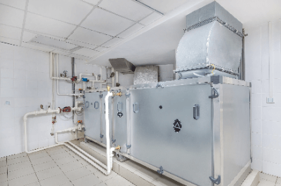
An Air handler is air conditioning equipment installed in certain large facilities, such as large commercial buildings, offices, and schools. The function of the equipment is similar to that of air conditioners used in ordinary homes. However, they differ from ordinary air conditioners in that they are centrally controlled by a central management system.

Unlike air conditioners, air handlers do not require the installation of an indoor unit in each room, and thus have the advantage of requiring only the air handler to be maintained. If an air handler breaks down, there is a risk that the entire facility will be without air conditioning, so it is necessary to take measures to distribute the units and provide backups.

Uses of Air Handlers

Air handlers are installed in the following types of facilities that have an area used for a specific purpose. 

  • 3,000 square meters or more: offices, department stores,  research facilities, etc.
  • 8,000 square meters or more: school facilities, training centers, hotels, etc.

In such specified buildings the indoor environment of “temperature,” “relative humidity,” “carbon monoxide content,” “carbon dioxide content,” “suspended dust,” “formaldehyde content,” and “airflow” must be controlled under certain standards.

In addition, explosion-proof air handlers are used in industrial facilities that handle highly flammable substances or volatile gases.

How to choose Air Handlers

When considering the installation of an air handler, it is necessary to compare the required environment with the Building Sanitation Law and sanitation management standards.

The required equipment and the environment to be maintained differ between the air quality standards when air conditioning equipment is installed and the air quality standards when mechanical ventilation equipment is installed.

Air conditioning equipment refers to “equipment” and “all ancillary equipment” that can regulate and supply “temperature,” “humidity,” and “flow rate” by purifying air taken in from outside using “air filters” and “electrostatic precipitators, etc.”. In other words, it refers to equipment equipped with the four functions of “purification,” “temperature,” “humidity,” and “flow rate control.

Mechanical ventilation equipment refers to “equipment that purifies air, etc. taken in from outside and supplies it by adjusting its flow rate.” In other words, it is equipment that lacks the functions of “temperature control” and “humidity control” among the functions of air conditioning equipment.

When considering the installation of air handlers, it is necessary to take into account which of the above categories they belong to. If it falls under the category of air handlers, necessary sanitary measures must be taken to prevent air contamination by pathogens. Examples of applicable items include “equipment cleaning of cooling towers and cooling water” and “inspection and cleaning of humidification equipment.

Principle of Air Handlers

Air handlers consist of a “filter,” “blower,” “heat exchanger,” “heating unit,” or “cooling water coil.”

These parts are housed in a metal case and installed in a dedicated machine room.

Unlike ordinary air conditioners, water, not gas, is used as the refrigerant. Air handlers keep indoor air fresh by drawing in outside air along with the ring air from each room. The outside air is also taken in together to reduce the temperature difference between indoor and outdoor air to avoid unnecessary energy use. After that, the captured air is purified through filters. This cycle is repeated as the purified air is supplied to each room after its temperature is adjusted by a cold water coil for cooling and a hot water coil for heating.

Since the air handlers itself perform heat exchange in this way, there is no need to install outdoor units in each room if the system is installed in a basement or other location. This makes it possible to make effective use of the limited space in the building.

Since the range of functions and sanitary control standards required for each facility where air handlers are installed differs, options such as air purification and humidification functions are ordered from the manufacturer in the form of build-to-order production.