カテゴリー
category_usa

Rotation Sensor

What Is a Rotation Sensor?

Rotation Sensors are sensors that obtain information about the rotational motion of a machine.

Specifically, it detects the rotation angle, rotation speed, and amount of rotation based on changes in physical quantities associated with the rotation of a machine. Rotation Sensors are not used by themselves, but are connected to a PC or meter.

There are four main types of Rotation Sensors: the mechanical type recognizes the angle of rotation, the optical type detects the passage of light, and the magnetic or electromagnetic induction type is related to changes in magnetic fields. Each is used according to the physical quantity to be detected.

Uses of Rotation Sensors

Rotation Sensors are used in a wide variety of machines to detect the state of rotational motion of a machine. Examples include automobiles, motorcycles, agricultural machinery, ships, and other vehicles driven by engines or motors. In the case of automobiles, Rotation Sensors are used to detect the crank angle and cam angle of the engine, the number of revolutions of the crankshaft of the engine and the output shaft of the transmission, as well as in ABS (anti-lock braking system).

Rotation Sensors are also used to detect the rotational position of machines other than those in continuous rotational motion. As potentiometers, Rotation Sensors are also useful for detecting the angle of rotation of a machine.

Principle of Rotation Sensor

Rotation Sensors are available using several principles, depending on their purpose. Here we describe four typical types. 

1. Mechanical (Contact Type)

Mechanical Rotation Sensors use a variable resistance to detect the rotational position by sensing the electrical resistance corresponding to the angle of rotation. Mechanical Rotation Sensors are used not only for continuous rotational motion, but also as potentiometers, gear position meters, etc., to detect the position during circular motion.

2. Optical Type

Optical Rotation Sensors consist of a disk mounted on a rotating shaft with a series of small holes, called slits, through which an optical sensor detects the blinking speed of light passing through the slits as pulses. The optical sensor converts the light pulses into electrical signals. The optical type features high detection accuracy and resolution depending on the shape of the slit.

3. Magnetic Type

Magnetic Rotation Sensors detect changes in the magnetic field distribution by means of a magnetic sensor with a permanent magnet attached to the rotating shaft. Magnetic sensors use a semiconductor material called a Hall element. It is capable of detecting the rotational position and rotational speed of the motor shaft.

4. Magnetic Induction Type

Rotation Sensors of the magnetic induction type have an induction coil (excitation coil) and a fixed coil (detection coil) mounted alternately on the rotating shaft to read changes in the magnetic field caused by rotational motion. Magnetic Induction Rotation Sensors are also called Resolvers. They can be used over a wider temperature range than other sensors and have excellent environmental resistance.

5. MR (Magnetoresistive Element) Sensor

The MR Sensor detects rotational speed from the strength of the magnetic field generated as the gear passes by a permanent magnet placed near the tip of the gear teeth mounted on the rotating shaft. The magnetic field works in the direction that the distance between the gear tooth tip and the sensor becomes shorter.

MR sensors are used in various parts of automobiles.

Other Information on Rotation Sensors

Example of Use in ABS

Among the products we use in our daily lives, many Rotation Sensors are used in automobiles, including ABS devices. This system prevents the tires from locking up when emergency braking is applied.

If the tires lock up, the car cannot change its direction of travel even when the steering wheel is operated. Therefore, ABS prevents the tires from locking and enables the driver to avoid collision with an obstacle by steering wheel operation. The ABS system is activated when the Rotation Sensor detects a sudden drop in tire speed.
カテゴリー
category_usa

Capacitive Proximity Sensor

What Is a Capacitive Proximity Sensor?

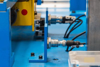
Capacitive Proximity SensorCapacitive Proximity Sensors are a type of non-contact sensor that detect the presence or absence of an object. They can detect an object by the change in capacitance when the object enters the electric field.

Various substances can be detected, including metal, water, oil, glass, plastic, and paper. It can also detect the contents of non-metallic containers from the outside.

However, it should be noted that detection sensitivity and distance vary depending on the object’s object size, thickness, and non-dielectric constant, as well as its susceptibility to water and moisture.

Uses of Capacitive Proximity Sensors

Capacitive Proximity Sensors are used for detecting the contents of a container from the outside and for non-contact switching.

1. Detection of Contents From Outside the Container

Capacitive Proximity Sensors are capable of detecting liquids, paper, glass, and wood behind walls, inside tanks, inside containers, and behind covers. They are mainly used for inspection and confirmation of contents.

2. Non-Contact Switches

They are used as push-button switches in elevators, switches through various panels, etc., and non-contact switches for lights, etc. They are also applied to switches for lighting and dimming room lamps in cars.

Principle of Capacitive Proximity Sensors

The principle of capacitive proximity sensors is that an object can be detected by the change in capacitance when the object enters an electric field.

When voltage is applied to an electrode and the ground, an electric field is formed between the electrode and the ground. When an object enters the electric field formed by the electrodes, the object is charged by electrostatic induction and the electrode’s capacitance changes.

1. Detection Circuit

Capacitive Proximity Sensors have a sensing electrode. When a dielectric detector enters the electric field formed by the sensing electrode, the electrode forms a capacitor with the object. The capacitance is determined by the distance to the object.

An oscillation circuit is commonly used for the detection circuit. The oscillation amplitude changes as the capacitance of the sensing electrode changes. An object is detected by comparing the amplitude changes that the oscillation circuit starts and stops. In capacitive proximity sensors, the sensing electrode is the element and oscillates.

2. Oscillation Circuit

An oscillation circuit is an electric circuit that generates electrical repetitive oscillations. An RC circuit consisting of a capacitor (C) and a resistor (R) is used to generate oscillations with frequencies ranging from 1/1,000 to several MHz.

3. CR Oscillation

CR oscillation is an oscillation circuit called a feedback type. A portion of the output of the amplifier circuit is fed back to the input to produce regular voltage fluctuations. The CR oscillation circuit rotates the phase of the amplifier output 180 degrees and returns it to the input.

Other Information on Capacitive Proximity Sensors

1. Mutual Interference

The use of a high-frequency oscillation circuits may cause mutual interference when proximity sensors are nearby. When multiple sensors are installed, they should be installed at a distance greater than the specified distance. 

2. Change in Capacitance

Changes in capacitance are related to the size, thickness, and non-dielectric constant of the object. The larger each of these values is, the larger the capacitance will be.

Dielectric constant is an inherent electrical constant possessed by each material. The value of the dielectric constant is determined by how the electrons in each material respond to an external electric field. The non dielectric constant is expressed as the ratio of the dielectric constant of the material to the dielectric constant of a vacuum.

Because of its susceptibility to water and moisture, selection and installation considerations are important.

3. Metric Tolerance

When a standard sensing element is brought close to the sensing surface, the distance from the sensing surface to the sensing element when the switch of the capacitive proximity sensor operates is called the sensing distance. When the detector is moved away from the sensor switch during the detection operation, the switch returns to its original position. At this time, the distance between the sensing surface and the detector is called the return distance.

Hysteresis is the ratio of the difference between the return distance and the detection distance, and is one of the indicators of detection characteristics of capacitive proximity sensors. The hysteresis is approximately 1 to 15% of the sensing distance.

カテゴリー
category_usa

Safety Limit Switch

What Is a Safety Limit Switch?

Safety Limit Switch

Safety Limit Switches are limit switches that have a direct open circuit operating mechanism and are used when reliability is required to ensure machine safety.

They are mainly used as sensors for interlocking devices in production equipment. Unlike ordinary limit switches, they do not lose their function as limit switches even if the contact points in the switch are welded due to a short circuit or high voltage application.

This makes it possible to realize safer interlock devices.

Applications of Safety Limit Switches

Safety Limit Switches are mainly used in the interlocking devices of machines that require a high level of reliability. Typical examples of interlocking devices are safety guards and doors that can be opened and closed. When the mechanism is closed, the switch is pressed to open the contacts, which are then verified by the control system to command the actuator to allow operation.

If the mechanism is open, for example during inspection, the switch is not depressed and the contacts are closed, so that the actuator will not start operation even if it is operated accidentally.

Principle of Safety Limit Switches

1. Direct Circuit Actuation Mechanism

Ordinary limit switches use springs to close and open the contacts when the switch is physically pressed, so that if the contacts are welded for some reason, the switch will not return and the hazardous condition cannot be communicated to the system.

Safety Limit Switches, on the other hand, use a direct opening mechanism that opens the contacts when the switch is depressed. This means that even if the contacts are welded, the welding can be released by the force of depressing the switch.

2. Fail-Safe Design

Even in the unlikely event that the welding is too strong to be released, the safety guard and door cannot be completely closed if the interlock device is designed with high accuracy. The device can be designed to be fail-safe such that it recognizes it as a dangerous condition and does not start operation.

This action of opening the contacts directly by an external actuator, such as opening or closing a door or rotating a cam, is called positive action. It is recommended that switches with this action be used as stand-alone interlocking devices.

Other Information on Safety Limit Switches

1. Mechanism to Prevent Contact Welding

A direct-circuit actuation mechanism is a switch mechanism that uses the force acting on the actuator to pull the contacts apart when the NC (normally closed) contacts of a safety switch are welded together. With direct circuit actuation, only NC contacts are available.

The contacts, also called NO (normally open) contacts, are represented by an arrow mark near the switch contacts in direct circuit actuation mechanisms. In contrast, safety relays use a technique called forced guiding.

This is a relay mechanism that prevents the NO and NC contacts from turning ON simultaneously when the safety relay contacts are welded together. The advantage is that by monitoring one contact, it is possible to diagnose whether the other contact is normal. However, the contacts cannot be pulled apart as in a direct circuit operating mechanism.

2. Interlock Device

Interlock is the concept of a safety device or safety mechanism to protect the safety of operators and users. It refers to a mechanism that prevents other operations unless certain conditions are met. It is applied to ensure worker safety in factories where robots, equipment, and various machines are in operation.

It is important to take measures to stop the equipment in an emergency if the worker approaches the equipment so closely that he/she unintentionally comes in contact with a part of the equipment. In addition, inspection work requires workers to be even closer to the equipment than normal work, so it must be performed after further ensuring the safety of the workers. Since equipment malfunctions can lead directly to accidents, it is necessary to ensure that interlocks are implemented as a preventive measure.

カテゴリー
category_usa

Cement Resistor

What Is a Cement Resistor?

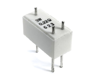
Cement ResistorA cement resistor is an electronic circuit component that acts as a resistance to the current flowing in a circuit.

There are various types of resistors, of which cement resistor is classified as wire-wound resistors. This is because many of them use wire-wound resistive elements to block the flow of electricity. Some cement resistors use resistance elements other than wire-wound resistors.

Wire-wound resistors are classified according to the material of the case covering the outside. Besides cement resistors, there are wire-wound resistors, metal-clad resistors, and enamel resistors.

Uses of Cement Resistors

Cement resistors are resistors in electronic circuits that impede the flow of current. They are used to limit current, divide voltage, or detect current, depending on the purpose.

In many cases where cement resistors are used, the temperature of the resistor is high or the humidity is high enough to cause severe deterioration of the resistor. Resistors are also classified according to the power they can use, but cement resistors fall into the medium capacity class (10 W or less) for power circuits.

Cement resistors have excellent heat, moisture, and vibration resistance because the resistors are surrounded by cement. Therefore, most of them are mounted on electronic circuit boards used in outdoor high-power equipment.

Principle of Cement Resistors

Cement resistors are resistance in an electronic circuit, which is expressed as resistance in Ohm’s law. Ohm’s law is expressed by the following equation

V (voltage) = R (resistance) x I (current)

The unit of resistance is the ohm (Ω), which can be found in cement resistor catalogs. In cement resistors, a resistive element, which provides electrical resistance, is encapsulated in cement. When an electric current flows through the resistive element, it generates heat, and its role is to dissipate the heat little by little so that the heat is not easily transferred to the surroundings.

Most resistive elements are wire-wound resistors, but metal oxide film resistors are sometimes used for large resistance values (100 Ω or more). Because of their excellent environmental resistance, they are used outdoors in adverse environments such as high temperatures, high humidity, and intense vibrations.

Most cement resistors are wire-wound type resistors, and their structure is the same as that of a coil. Therefore, they have an inductance component. Because of this effect in the high-frequency band, it is safer to avoid using them in circuits that operate at high speeds, such as high-speed switching, because they may generate unexpected noise.

Other Information on Cement Resistors

1. Advantages of Cement Resistors

The cement used for the casing of cement resistors is non-flammable. Since it does not ignite even at high temperatures, its advantage is that it can be mounted directly on a circuit board. Cement resistors are suitable for use as stable power circuits in harsh environmental conditions.

2. Disadvantages of Cement Resistors

Most cement resistors use wire windings for the resistive elements, which create inductance. When used in high-frequency AC circuits, this results in an increase in impedance. The disadvantage is that these phenomena may cause unexpected noise in circuits operating at high speeds, such as high-speed switching.

Inductance is a phenomenon in which an increase in the current flowing through a coil causes the coil itself to work to reduce the flow of current, and conversely, a decrease in the current causes an increase in the current flowing through it.

Impedance is the ratio of voltage to current in an AC circuit, and it works to impede the flow of current. It expresses the difficulty of current flow and is equivalent to resistance in a DC circuit.

カテゴリー
category_usa

Low Temperature Thermostat

What Is a Low Temperature Thermostat?

Low Temperature ThermostatsA Low Temperature Thermostat is an environmental testing device that allows the temperature inside the incubator to be set between low and high temperatures (approximately 0°C to 60°C or approximately -10°C to 50°C).
There are large models that can be programmed to change the temperature at a set time, as well as small models that can be used on a tabletop.

Uses of Low Temperature Thermostats

Low Temperature Thermostats are a type of environmental testing equipment used for testing in fields where changes in samples at low temperatures are important. The main applications include storage and storage-related tests in the food industry, low-temperature environment tests for animals and plants, and low-temperature experiments in the biochemistry field.

Low-temperature constant-temperature conditions are also essential for some applications, and are useful for microorganism culture and preservation tests, as well as for plant and animal tissue culture and preservation tests. In addition, they is also used for durability and deterioration tests of various parts and devices.

Major applications include endurance and degradation tests in which temperature and time are programmed to reproduce temperature changes over a 24-hour period, endurance and degradation tests in which temperatures are varied to extremes of low and high temperatures, and accelerated tests of these tests. For this reason, they are installed in educational, testing, and research institutions around the world.

Principle of Low Temperature Thermostats

Low Temperature Thermostats are devices that maintain the temperature inside a chamber at a relatively low temperature. The chamber in which samples are placed has an outer wall with a heat-insulating structure that prevents the internal temperature from being affected by the external environment.

Therefore, this structure minimizes the influence of external temperature changes and keeps the internal temperature constant.

Low temperature thermostats are broadly classified into two types according to the method used to control the temperature inside the chamber: the air circulation method and the air jacket method. They are explained in the following order:

1. Air Circulation Method

In the air circulation method, a fan is used to agitate the air in the chamber to equalize the temperature. In this method, there is a device that produces temperature-controlled air outside the chamber where the sample is placed.

This air is then fed into the chamber, and a fan is used to expand and circulate the air inside the chamber to equalize the humidity distribution inside the chamber.

This system is used in relatively large low temperature thermostats. 

2. Air Jacket Low Temperature Thermostat

The air jacket method does not have a fan. It has a layer of circulating air called an air jacket on the outside of the chamber. This layer generates airflow to control the temperature by heating and cooling.

Natural convection maintains a uniform temperature inside the chamber surrounded by the air jacket. In this method, there is not much dry air or excessive airflow in the chamber where the specimens are stored, which reduces damage to the specimens.

Other Information on Low Temperature Thermostats

1. Low Temperature Thermostats with Peltier Element

Some low temperature thermostats are relatively small and use a Peltier device to heat and cool the chamber. Peltier devices are semiconductors that transfer heat from a heat-absorbing surface to a heat-generating surface when electricity is applied. In such low temperature thermostats, the Peltier device is in direct contact with the outer wall of the chamber in which the sample is placed to heat and cool the interior.

Low Temperature Thermostats using Peltier elements are very compact and can be used on a tabletop. For example, some are suitable for the incubation and storage of small quantities of microtubes, vials (1-10 mL), centrifuge tubes, and petri dishes.

These small low temperature thermostats do not have the inconvenience of unstable temperatures caused by opening and closing the door, which can be a problem with larger capacity incubators. 

2. Difference Between Low Temperature Thermostats and Incubators

Incubators also include devices used to protect living organisms, such as incubators for newborns. The critical difference between the two is that incubators sold for incubator use, for example, can be set at temperatures ranging from about 20°C to 40°C, which is a narrower temperature range than that of low temperature thermostats.

Some incubators also have an egg-turning function, which is necessary to return the eggs, and a humidity control function, which is necessary to create an incubation environment, and cannot be used as a replacement for low temperature thermostats.

Whether a device labeled as an incubator is a low temperature thermostat or an incubator can be determined by the temperature setting range. For example, an incubator that can be controlled from -10°C to 60°C is a low temperature thermostat, while one limited to a temperature range near body temperature of 30°C ± 10°C is an incubator.

カテゴリー
category_usa

Fiber Amplifier

What Is a Fiber Amplifier?

Fiber Amplifiers

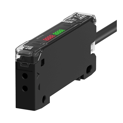
A Fiber Amplifier is an amplifier used to amplify optical signals.

When optical signals are propagated in an optical fiber, they are attenuated by transmission or distribution, and the amplifier compensates for this. Conventionally, optical signals are amplified electrically by a semiconductor IC, etc., then reconverted to light and re-transmitted.

Fiber Amplifiers, on the other hand, can amplify optical signals directly in optical fibers, and are widely used in the field of optical communications.

Applications of Fiber Amplifiers

Fiber Amplifiers (Optical Fiber Amplifiers) are widely used in the field of optical communication using optical fibers, especially for long-distance optical communication applications where attenuation of light during propagation inside the fiber is an issue.

Amplification of optical signals using rare-earth element-doped fiber, which is the mainstream, has high output power. It can also amplify optical signals with high modulation frequencies and wavelength multiplexing, which cannot be handled by electrical amplification using semiconductors, and thus can handle optical signals with large amounts of information.

Taking advantage of these characteristics, fiber amplifiers are used in long-distance relay systems, optical multi-distribution systems, and optical frequency multiplexing systems in optical communications.

Principle of Fiber Amplifier

Fiber Amplifiers (optical fiber amplifiers) are mainly composed of rare-earth doped fibers and pump laser diodes (pump LDs) and amplify optical signals by utilizing the physical phenomenon of induced emission.

When rare earth ions are excited by the pump LD, the input signal light is triggered and amplified as an optical signal without conversion to an electrical signal by induced emission. Other components include a WDM coupler to combine the input signal light and pump light, and an optical isolator to prevent the amplified light from oscillating.

Rare earth ions can be used for amplification in the 1.3μm band for Pr ions, the 1.5μm and 0.85μm bands for Er ions, the 1.4μm and 2μm bands for Tm ions, and the 1.0μm band for Yb ions, corresponding to their energy levels, especially in the 1.3μm, 1.4μm and 0.85μm bands. Fluoride fibers are used for amplification instead of quartz fibers.

Types of Fiber Amplifiers

1. Erbium-Doped Fiber Amplifier (EDFA)

Since quartz optical fibers for long-haul optical communications have a minimum loss at a wavelength of 1.55μm, long-haul optical communication transmission networks have been constructed using semiconductor lasers with wavelengths in this range as light sources. Long-haul optical communication transmission networks extend over several hundred kilometers in some cases, so the loss used to be converted from light to electrical signals, electrically amplified, and then converted back to light and injected into the optical fiber.

With the advent of erbium-doped Fiber Amplifiers (EDFAs), optical signals in the 1.55-μm band can be amplified as they are when used in combination with incident light from 0.98-μm and 1.48-μm pump laser diodes, and this has become the dominant technology in current long-distance optical communication systems.

2. Fiber Raman Amplifier (FRA)

In addition to erbium-doped optical fiber amplifiers, fiber Raman amplifiers (Fiber Amplifiers) are another type of fiber amplifier that has recently been attracting attention.

This technology is expected to be applied to wavelength-division multiplexed optical fiber communications (WDM) because it is a physical phenomenon with freely settable wavelengths and relatively broadband gain. However, the need for high-power excitation light is an issue. Manufacturers are working hard to develop the technology, including the technology to develop the laser light.

Other Information on Fiber Amplifiers

1. Development for Fiber Sensors

Products called Fiber Sensors, which consist of a Fiber Unit photoelectric sensor, and a Fiber Amplifier for detection in confined spaces, are also widely used mainly in industrial applications. Fiber sensors generally use pulse-modulated light and are capable of non-destructive inspection applications in confined spaces and color discrimination, and have high-speed response.

They can be used in sensor applications suitable for checking workpieces and emissions in high-temperature environments.

2. Fiber Amplifier for the Next Generation

In addition to the conventional 1.55μm (C-Band: 1.53 to 1.565μm) long-wavelength light source Fiber Amplifiers, the shorter wavelength O-band (1.26 to 1.36μm) and S-band (1.46 to 1.53μm) Fiber Amplifiers have recently attracted attention in order to meet the strong demand for optical communication applications.

Some manufacturers are producing their own Fiber Amplifiers optimized for these bands by developing special materials.

カテゴリー
category_usa

MEMS Oscillator

What Is a MEMS Oscillator?

A MEMS oscillator is an oscillator that generates a clock signal source essential to electronic devices using a MEMS-structured resonator.

While quartz crystal devices have been commonly used for oscillators in the past and are still used in many cases today, MEMS oscillators utilize a thin-film microfabrication process technology called MEMS (micro-electro-mechanical systems) structure for resonance points.

A MEMS oscillator is characterized by its ability to be used in small timing devices, excellent resistance to shock and vibration, and high reliability. MEMS oscillators are highly regarded compared to conventional timing devices.

Uses of MEMS Oscillators

MEMS oscillators are used in various electronic devices that require timing and clock signals. Specific applications include a wide variety of electronic devices such as cell phones, PCs, wearable devices, automotive-connected devices, and medical equipment.

With the introduction of 5G in recent years, which has led to higher line speeds and the rise of IoT, the market for automatic driving and VR devices is also expected to expand, and shipments are expected to grow markedly in the future.

The Principle of MEMS Oscillators

The principle of MEMS oscillators is that the resonator of the oscillator is made of MEMS, a thin-film microfabrication technology, and the resonator is made of single-crystal silicon with tensile strength 14 times greater than that of titanium.

Unlike quartz devices, which use the piezoelectric effect for a piezoelectric drive, the MEMS resonator is driven by electrostatic excitation forces, and the MEMS oscillation circuit and the MEMS resonator are electrically connected, and a total oscillation maintenance circuit is activated to keep the MEMS resonator mechanically fixed at a certain frequency. The MEMS resonator can be made to oscillate at a fixed frequency.

Compared to crystal oscillators, MEMS oscillators can be set to any frequency using a phase-locked loop (PLL). On the other hand, there are some drawbacks, such as increased power consumption due to more complex circuit configurations, and noise characteristics that are easily degraded due to frequency jumps.

Other Information on MEMS Oscillators

1. Comparison of Temperature Characteristics With Crystal Oscillators

The basic structure of a crystal oscillator is a combination of a crystal unit and an ASIC oscillator circuit. In this case, the temperature sensor used to correct the temperature characteristics of the oscillator is built into the ASIC.

Therefore, compared to a MEMS temperature sensor that can be formed on the same chip, the change in oscillation frequency concerning temperature change may be larger.

MEMS oscillators not only have the advantage of small changes in oscillation frequency with temperature change but also have the advantage of small mass and small characteristic fluctuation due to vibration.

2. Noise Characteristics

Noise characteristics of oscillators are a very important factor in ensuring good application characteristics. In particular, crystal oscillators have the advantage over MEMS oscillators in that the crystal structure itself is very simple, making it easy to obtain low noise characteristics.

However, compared to MEMS oscillators, crystal oscillators are more prone to jitter during vibration due to their larger mass. Therefore, depending on the application environment, MEMS oscillators may be more suitable in terms of noise characteristics.

3. Frequency Deviation

While MEMS oscillators are less cost-effective than competing ceramic oscillators and other types of oscillators, they can ensure excellent oscillation frequency stability. The frequency deviation of general ceramic oscillators is as large as about 1%, which limits the applicable applications, while MEMS oscillators can achieve frequency deviation as low as on the order of ppm.

カテゴリー
category_usa

Power Monitoring

What Is Power Monitoring?

Power Monitoring is the process of measuring and monitoring the amount of electricity or power used.

Electricity is an energy that cannot be visually monitored for usage, but must be purchased from the power company if you do not have a power generation facility. Therefore, in order to ensure that the electricity bill is reasonable, it must be monitored using a watt-hour meter or a power monitoring system.

Traditionally, the purpose of power monitoring has been to reduce the cost of electricity. In recent years, it is not only for that purpose, but also as part of environmental protection activities such as CO2 reduction.

Electricity is an energy source that tends to account for a large proportion of business activities. Therefore, power monitoring is one of the most important items in energy management.

Uses of Power Monitoring

Power Monitoring is an activity that is widely implemented in commercial and industrial settings. It may also be implemented in homes.

The following are some examples of power monitoring:

  • Power monitoring in large facilities
  • Electricity generation monitoring in commercial facilities with solar panels
  • Daily power monitoring for households

Companies and organizations with large facilities often install power monitoring systems. These systems often allow the user to see not only the power consumption of the entire facility, but also the usage by facility and sector. Detailed analysis of energy consumption status is possible, allowing for efficient energy conservation studies and power management.

Facilities with solar panels or generators may also provide power monitoring of power generation. In recent years, power usage at home can also be managed through the development of applications by electric power companies.

Principle of Power Monitoring

Power Monitoring is done mainly by measuring current, voltage, and power factor. Electricity is obtained by multiplying current and voltage. However, as the current and voltage shift out of phase, no power is effectively consumed.

Power can be calculated not only by multiplying the RMS values of current and voltage, but also by the power factor, which is the ratio of phase matching.

Current transformers (CTs) are commonly used to measure current, and voltage transformers (VTs) are commonly used to measure voltage; the current and voltage measured by CTs and VTs are calculated by wattmeters and converted to electric power while calculating the power factor. In the case of watt-hour meters, the power measured by these devices is integrated over time and output as electric energy.

The power generated by out-of-phase currents and voltages is called reactive power. When reactive power is generated, current that is not consumed by the load travels back and forth across the transmission line, putting pressure on the transmission facility capacity, which is disadvantageous to the power company. Therefore, when concluding a power contract for high-voltage or higher, a discount item for maintaining a high power factor is often included.

Structure of Power Monitoring

Electricity contracts for residential use are generally ampere contracts. Although the upper limit of the current is fixed by the ampere contract, if more load devices are connected, the current will exceed the contracted amount. However, under an ampere contract, if the number of load devices increases, the breaker will shut off the power supply when the current exceeds the contracted current.

On the other hand, facilities that receive power under high-voltage or special high-voltage contracts are uneconomical because of the time and effort required to restore power if power is interrupted. In public facilities such as hospitals, human lives may be at stake. Therefore, electric power companies often conclude power contracts on a demand charge basis, rather than shutting off power when the maximum limit is exceeded.

The demand charge system is a system in which the contracted power is based on the upper limit of the expected 30-minute average power; both the customer and the power company monitor the 30-minute average power value, and if the contracted power is about to be exceeded, the customer responds by limiting the power used. If the contracted power is exceeded, the power company will charge a penalty or review the contracted power.

Management of the 30-minute power forecast under the demand charge system is called demand monitoring. For consumers with high-voltage or higher, power monitoring is performed by installing a power monitoring system capable of monitoring the 30-minute average expected power consumption value on a minute-by-minute basis and limiting the power consumption.

カテゴリー
category_usa

Environmental Sensor

What Is an Environmental Sensor?

Environmental Sensors

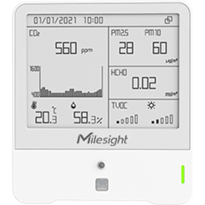
An Environmental Sensor is a sensor used to detect and quantitatively measure environmental information in the surrounding environment.

Environmental Sensors are used to measure various environmental parameters such as temperature, humidity, light intensity, CO2 concentration, atmospheric pressure, noise, etc., as well as to detect the human body.

Recently, there are products that incorporate multiple environmental sensors in a small USB-type package to improve the convenience of evaluation.

Uses of Environmental Sensors

Environmental Sensors are sometimes used by themselves to display information, but more often they are used to detect external environmental information to control other devices or equipment.

Examples of specific uses include devices that require temperature and humidity control, automatic doors and lighting that are activated by approaching humans, automobiles, aircraft, and detection of exhaust gases and occupants.

In automobiles, the purpose is to measure outside air, interior temperature and humidity, and solar radiation to determine the temperature and airflow rate of air conditioners.

In aircraft, they are also used for the purpose of controlling the attitude of the aircraft.

Principle of Environmental Sensors

The principle of environmental sensor is to convert information to be detected, such as temperature and humidity of the environment, into electrical signals by utilizing various physical phenomena, and to grasp them as quantitative values.

Environmental sensors generally target external inputs (weather information, light, obstructions, sound, etc.), and many sensors have the ability to amplify and output weak signals or convert measurement units.

A typical environmental sensor, the highly versatile temperature/humidity sensor, is often integrated as a device, but temperature and humidity are measured separately, and temperature is generally detected by a thermocouple or thermistor. Thermocouples utilize the potential difference between two different metal wires. Thermistors can detect temperature with a resistive element composed of a metal wire and a metal oxide semiconductor.

Among them, NTC thermistors are widely used because they have a negative correlation in which the mobility of electrons increases and resistance decreases as temperature rises, making the relationship between temperature and resistance easy to understand.

Humidity sensors measure the amount of water vapor in the air and convert it to humidity as a ratio to the maximum amount of water vapor that can exist in the air.

There are two types: one that measures changes in semiconductor capacitance and the other that measures changes in semiconductor resistance. Resistance detection is less expensive, but it should be noted that the measurement accuracy is inferior to that of the capacitance type.

Other types of environmental sensors include optical and illuminance sensors that detect light such as infrared and ultraviolet rays. These sensors use photodiodes that utilize the photoelectric effect and photoresistors compatible with various wavelengths to detect light intensity. Most of these sensors also detect infrared light emitted from the human body.

Other Information on Environmental Sensors

1. Environmental Sensor as an Indicator of Arousal

CO2 sensors, one type of environmental sensor, are sometimes used as an indicator of arousal in a room. CO2 sensors mainly measure the concentration of carbon dioxide generated by human respiration, and can be used in places where many people gather, such as conference rooms and hospital waiting rooms.

In places where many people gather, such as classrooms, if the concentration of carbon dioxide is too high, it is said to affect the ability of people to concentrate, which is expected to improve work efficiency.

2. Miniaturization of Environmental Sensors

Environmental Sensors are also becoming smaller and smaller. Some of the smallest environmental sensors are less than 1 cm in size, and can be used in various fields such as medicine, agriculture, and manufacturing.

There are also USB-type environmental sensors. They are smaller than ordinary USB memory sticks and can be powered by USB for constant operation, and can be connected to a network via USB or Bluetooth for transmission of measurement data.

However, when connected to a PC’s USB port, the temperature sensor may not be able to measure temperatures correctly due to the heat of the PC itself, so it is recommended to use an extension cable.

カテゴリー
category_usa

Conductive Paste

What Is a Conductive Paste?

A conductive paste is a mixture of metal particles (filler), organic materials (various resins), surfactants, and polymers (binders).

A conductive paste is applied to the part to be made conductive and heat-treated to make it conductive at the same time as it is bonded. Other methods of adding conductivity include soldering and bonding with conductive tape, but the elements expected of conductive paste include lead-free, low temperature, heat resistance, and low weight.

In recent years, in particular, there has been a remarkable innovation in low-temperature technology, and its application in the semiconductor field is flourishing. In contrast to the melting temperature of solder, which is approximately 360°F (425°F for lead-free solder), materials with a processing temperature of less than 212°F are now in practical use for conductive paste. Another feature of conductive paste is that it is more flexible than solder adhesion.

Because of its advantage of being easily used at low temperatures, conductive paste is widely used in scientific experiments as well as in applied settings. For example, in scanning tunneling microscopes (STM) and other applications where there is a need for conductivity between the specimen base and the specimen, a conductive paste can be applied to the specimen without applying excessive heat to it.

Uses of Conductive Pastes

Conductive pastes are mainly used as a conductive adhesive for electronic devices used in smartphones and PCs. It is also often used in scientific experiments.

As electronic devices continue to become smaller and lighter, lower temperatures for conductive adhesion have become an essential issue for the semiconductor industry. In addition to the fact that conductive pastes are lead-free, this background is another reason why low-temperature bonding with conductive pastes is gaining prominence.

Conductive pastes are also used for in-vehicle modules such as drive recorders, where the excellent heat resistance of conductive pastes is expected to prevent deterioration of product quality even when the vehicle is hot during the day.

Principle of Conductive Pastes

Conductive pastes are made by dispersing metal nanoparticles with high conductivity in organic material and hardening the resin to give conductivity between joined objects. Ag (silver), which has high thermal conductivity, is the most commonly used metal particle mixed in conductive pastes.

Conductive pastes with silver particles are called silver pastes. Other metals include Ni (nickel), Au (gold), Cu (copper), and C (carbon).

On the other hand, there is a wide variety of organic materials and polymers that can be mixed into conductive pastes, depending on the application and the manufacturer. For example, epoxy resins, phenolic resins, acrylic resins, urethane resins, and silicone resins are used.

Although metallic nanoparticles and organic materials are mixed to prevent agglomeration, the stability, heat resistance, and other properties of conductive pastes vary depending on the combination of organic materials and polymers to be mixed.

How to Select Conductive Paste

Conductive pastes cannot be used in places where it is heated to high temperatures because of their low processing temperature. However, some products have high-temperature resistance and low degas, so it is important to select the type of conductive pastes that best suits the application.

Another feature of conductive pastes is that if it is not heat-treated, it is coated with an organic material and is not conductive. Some types can be used simply by drying without heat treatment, which hardens the resin. Note that workability, long-term storage stability, curing conditions, adhesive strength, and resistance to moisture and heat vary depending on the type of binder used.

It is recommended to use conductive pastes with a binder that is appropriate for the place to be made conductive. Since some require refrigeration for storage and some may harden and become unusable if stored for a long period, it is necessary to check the instruction manual for the conductive pastes being used.