カテゴリー
category_usa

FPGA Board

What Is an FPGA Board?

An FPGA board, also known as an FPGA evaluation board or FPGA development board, is a board equipped with an FPGA (Field Programmable Gate Array) and peripheral components. It is primarily used in the initial stages of FPGA development or for educational purposes related to FPGA development.

FPGAs are typically mounted on dedicated boards tailored to specific product specifications. However, since these dedicated boards take time to develop, FPGA boards are often used for early-stage evaluation of FPGAs in product development. These boards usually come pre-installed with various interfaces necessary for FPGA development.

Uses of FPGA Boards

FPGA boards facilitate the evaluation and validation of product development, both in terms of the IC circuitry (hardware) related to the FPGA and the software needed to operate the FPGA. They offer versatility during the product development stage, allowing designers to verify the operation of the IC during the development process, even if the evaluation board with dedicated peripheral circuit components is still under development.

Principle of FPGA Boards

To operate an FPGA, essential components include the FPGA IC, a board connecting the IC to various power supplies and bias wiring, and embedded software on a PC for sending digital control signals. FPGA boards package and integrate these components, enabling the evaluation and verification of FPGA’s electrical circuit system operation.

FPGA boards often come with a variety of interfaces and function libraries from different manufacturers. However, more sophisticated models can be very expensive.

Other Information on FPGA Boards

1. Use of FPGA Boards

FPGA boards are used for preliminary evaluation and development of FPGA-based products, operation verification of embedded application software, IC evaluation and verification of digital circuits, and as introductory tools for FPGA-related design. They are available in a range of functionalities and complexities, from high-performance specialized boards to beginner-friendly ones. It’s important to select an FPGA board that suits the specific goals and requirements of the project.

2. Advantages of FPGAs Over ASICs

FPGAs have a built-in wiring system called Gate Array, allowing designers to programmably implement a variety of functions. While the performance of FPGAs may not match that of specially designed and optimized ASICs in terms of response speed and power consumption, they offer the flexibility of realizing desired functions immediately without incurring mask development costs. In the context of today’s advanced CMOS technology, where IC mask development can be both costly and time-consuming, FPGA boards are valuable tools for designers and developers, particularly when dedicated ASIC development is not feasible due to cost and volume considerations.

カテゴリー
category_usa

ERP Package

What Is an ERP Package?

ERP PackagesAn ERP (Enterprise Resource Planning) Package is a system that integrates and manages the various operations of a company.

ERP packages provide functions such as accounting management, sales management, logistics management, production management, and human resource and payroll management on a single system platform, enabling the centralization of information within a company. This facilitates information sharing and business collaboration between departments, improving operational efficiency and speed.

In addition, ERP packages standardize business processes, reducing the number and variation of employees, and contributing to improvements in quality and costs. Furthermore, management can make accurate decisions because they can monitor the status of each department and company-wide performance in real time.

Because ERP packages can be operated on a company-wide scale, they can also optimize facilities and human resources, making ERP packages an indispensable system for improving a company’s competitiveness.

Uses of ERP Packages

ERP Packages are used to streamline operations such as accounting, production, sales, logistics and human resources. Because the information required by each department and the methods of handling information differ greatly, the core business operations of a company have been managed by individual systems introduced for each department, and information has been processed in independent databases for each department.

However, when considered through the entire flow company operations, all of this separate business information from different departments is all related, as the information must ultimately be integrated into the accounting operations.

In the past, it took time, effort, and cost to cross over the databases of each separate department to reflect payroll information from human resource management or purchase sales information from sales management in the accounting process.

By implementing an ERP package, business management for each separate department can be linked and operated efficiently.

Principle of ERP Packages

Core systems refer to the various systems that support a company’s main business operations. They are called business systems or back-office systems, and are generally independent systems for each individual business.

However, separate mission-critical systems, which were created by different departments for their own convenience, had great difficulty in integrating necessary data, and could only handle each other’s data in a partial and fragmented manner. In today’s business world, where real-time, rapid, and accurate analysis of management data is critical, this problem can lead to significant losses.

In contrast, ERP packages do not require any linkage processing because multiple mission-critical systems are integrated in advance, and the databases and master data are handled in a single integrated manner from the beginning. Real-time, centralized data analysis is possible.

ERP Packages not only eliminate the time and cost of exchanging data across different departments, but also provide the information necessary to understand the company’s business situation in real time, quickly and accurately. This enables corporate management to make the best decisions necessary to improve management more accurately and more quickly than ever before.

Types of ERP Packages

1. On-Premise ERP Packages

A server is installed in the company where the ERP package is installed, the system is built, and is operated in-house. This type of system allows flexibility in the development of additional functions tailored to the company’s needs, and it is highly secure because it utilizes the company’s internal network.

On the other hand, the company must pay all initial costs such as the purchase of servers and maintenance costs such as personnel expenses for maintenance, and costs tend to increase.

2. Cloud-Based ERP Packages

This type of ERP package can be used over the Internet without installing a server in the company. It can be operated anytime and anywhere as long as there is an Internet connection. Since a server is not required, the introduction period is shortened and initial and operating costs are reduced.

On the other hand, since an Internet environment is always required, it may not be available in the event of a network failure. Furthermore, since all information is managed over the Internet, the possibility of information leakage must be considered.

3. Hybrid ERP Packages

There is also a hybrid type that utilizes the advantages of both on-premise and cloud computing, in which functions that contain important confidential information are operated on-premise, and data that is safe to have on the network is used in the cloud computing type.

Other Information on ERP Packages

ERP Package Market Trends

Recent trends in the ERP package market show that sales of package licenses are on the rise. Some analysts believe that DX (transformation of operations and business through the use of digital technology) has driven the expansion of the market, and ERP is being used more and more.

In addition, the use of cloud-based ERP packages has rapidly increased as teleworking and non-face-to-face business operations have been encouraged in recent years.

カテゴリー
category_usa

DPSS Laser

What Is a DPSS Laser?

DPSS Lasers

A DPSS (Diode Pumped Solid State) laser is a solid-state laser that utilizes a high-power semiconductor laser, known as a Laser Diode (LD), as its pump light source. LDs are advantageous because they can emit light at a single wavelength, are efficient at pumping, generate minimal heat, and have a long lifespan, resulting in a compact, lightweight, and durable laser system.

Uses of DPSS Lasers

DPSS lasers are employed in various fields due to their high-resolution capabilities. In biotechnology, they are used as light sources for confocal microscopes and DNA sequencing. In measurement applications, they serve as light sources for fluorescence spectrometers and Raman spectrometers, as well as in high-speed flow velocity particle measurement. They are also used for UV Raman spectroscopy and fluorescence imaging, especially the models with deep-ultraviolet single longitudinal mode output. Beyond measurement, DPSS lasers are utilized in laser processing, offering high output power and a compact oscillator.

Principle of DPSS Lasers

DPSS lasers typically comprise several key components: an LD as the excitation light source, a lens system for focusing LD light onto a laser crystal, a laser crystal for oscillation (commonly Nd: YVO4 or Yb: YAG), a nonlinear crystal (like KTP or BBP) for wavelength conversion, mirrors for resonance between the laser and nonlinear crystals, and a lens to collimate the output beam.

For instance, using Nd: YVO4 as the laser crystal, it can be excited by an 808 nm LD to emit 1064 nm infrared light. This infrared light can be converted into 532 nm green laser light by KTP. Furthermore, using BBP as another nonlinear crystal, the 532nm light can be transformed into 266nm UV laser light. This allows DPSS lasers to produce UV and visible light at various wavelengths through wavelength conversion.

カテゴリー
category_usa

DLC Coating

What Is a DLC Coating?

DLC CoatingsDLC coating, standing for Diamond-like Carbon, is a surface treatment technology known for its high hardness, wear resistance, low friction, and resistance to adhesion.

Uses of DLC Coating

DLC coatings are primarily applied to metals to enhance wear resistance, prevent seizure, and improve durability. Key applications include:

  1. Coating of automobile engines for durability
  2. Anti-wear coating for cutting tools
  3. Enhancing the durability of industrial robots
  4. Protective coatings for shafts and bearings in processing machines

Principle of DLC Coating

DLC is synthesized from diamond and carbon components. The process involves injecting acetylene gas and generating plasma under high frequency and voltage to break it down into carbon and hydrogen, with hydrogen being discharged. The ionized carbon then adheres to the negatively charged product, forming diamond-like non-crystalline structures on the surface. This coating effectively reduces the coefficient of friction for many materials, contributing to lower CO2 emissions.

Other Information on DLC Coating

1. Deposition Method of DLC Coating

DLC coating characteristics vary based on the deposition method:

CVD Method:
This method is faster than PVD, suitable for complex shapes, and can deposit thick films with hydrogen.
PVD Method:
Allows for hydrogen-free, high-hardness deposition with strong adhesion to base materials. Thicker films are more challenging to achieve.
Plasma Ion Implantation Method:
Enables room temperature deposition, applicable to materials like rubber, resin, and ceramics.

2. Demerits of DLC Coating

Drawbacks of DLC coating include:

  1. Risk of chipping, with the potential for fragments to mix in
  2. Poor adhesion to fabric
  3. Limited to coatings up to 2 microns thick
  4. Reduced hardness with increased hydrogen content

3. DLC Coating on Aluminum

DLC coating on aluminum provides wear resistance and low friction, reducing the weight of machine parts. However, the low affinity between carbon and aluminum can lead to adhesion issues. It’s commonly used for engine parts, with an intermediate layer required to match the boundary surface between the DLC film and the base material.

4 DLC Coating and Molybdenum-Based High Lubricity Lubricants

Wear issues have been reported with DLC coatings when used with molybdenum dialkyl dithiocarbamate oils. While DLC exhibits low friction in dry environments, it doesn’t perform as well as a boundary lubricant. The use of molybdenum disulfide increases durability against friction but is limited in wear resistance.

5. Peeling of DLC Coating

DLC coatings on materials like aluminum and brass may peel off under high load. Ensuring the substrate has high hardness can prevent this, allowing ions to penetrate the surface and create a strong bond with the coating.

カテゴリー
category_usa

DFB Laser

What Is a DFB Laser?

DFB Lasers

A Distributed Feedback (DFB) laser is a type of laser diode that produces a stable output wavelength. This stability is achieved by incorporating diffraction gratings at the boundaries of the diode layers, which amplify and emit only the light wavelength that matches twice the distance between the gratings. Unlike standard laser diodes, DFB lasers maintain a consistent wavelength regardless of current changes, operating environment, or modulation.

Uses of DFB Lasers

DFB lasers are primarily used in high-capacity, long-distance optical communications due to their ability to maintain stable output at a constant wavelength under various conditions. They are also employed in medical endoscopy, Raman spectroscopy, wavelength conversion, and gas testing. When selecting DFB lasers, factors such as allowable current, output wavelength, connection terminals, operating environment, and size should be considered.

Principle of DFB Lasers

DFB lasers consist of a p-type cladding layer, an n-type cladding layer, and an active layer sandwiched between them. During operation, forward voltage applied through the electrodes causes electron and hole recombination in the active layer, emitting light. This light is selectively amplified by the diffraction grating to produce a single wavelength output.

Temperature Characteristics of DFB Lasers

DFB lasers exhibit stable wavelengths with minimal temperature variation. Generally, the wavelength gradient is approximately 0.1 nm/℃. The oscillation wavelength is controlled by the grating period and temperature gradient. Efforts are underway to develop cost-effective, low-current DFB lasers that do not require external temperature control, using new materials and packaging methods.

1550 NM Wavelength, a Typical DFB Laser

In long-distance optical communications, wavelengths like 1550 nm are chosen for their low loss in optical fibers. This wavelength is particularly favored for long-wavelength DFB lasers. Other 1550 nm lasers include λ/4 phase-shifted grating DFB lasers and DBR lasers with gratings positioned away from the active layer.

Comparison With FP Lasers

Fabry-Perot (FP) lasers, another type of semiconductor laser, are often compared with DFB lasers. The main difference is FP lasers’ difficulty in achieving single-mode oscillation. FP lasers are used in CD/DVD optical pickups, laser printers, and similar applications.

カテゴリー
category_usa

CV Cable

What Is a CV Cable?

CV Cables
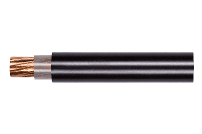
A CV cable, officially known as a “cross-linked polyethylene insulated vinyl sheath cable,” is commonly used in industrial power transmission. It employs cross-linked polyethylene for insulation and vinyl for the sheath layer.

Uses of CV Cables

Primarily, CV cables facilitate power transmission. In urban areas, these cables are often seen suspended from utility poles as supports. Distinguished by their core wire covered with vinyl sheath or polyethylene, CV cables are designed to withstand outdoor elements like wind, rain, and sunlight. Unlike vinyl-sheathed cables used in household power distribution, CV cables are not typically found inside homes.

Principle of CV Cables

High-voltage CV cables typically consist of multiple layers: a core wire (usually copper or aluminum), a semiconducting layer, cross-linked polyethylene insulation, a copper tape layer, and a vinyl sheath. The core wire acts as the electrical pathway, often composed of twisted thin copper wires for flexibility.

The semi-conductive layer, made from carbon-rich polymers, surrounds the core wire, preventing voltage-related deterioration of the cross-linked polyethylene insulation. An additional semi-conductive layer is placed outside the insulation, leading up to the copper tape layer. This layer, a thin copper film, contains electromagnetic emissions from the core wire and acts as a grounding pathway in case of insulation failure. The outermost vinyl sheath, usually black, offers corrosion protection and improved weather resistance.

In multi-core cables, insulating fibers like jute are used as inclusions between the sheath and copper tape layer to fill gaps. These cables, often three-core for compatibility with 3-phase power transmission systems, may utilize a triplex construction for enhanced heat dissipation and are also referred to as CVT cables.

Other Information on CV Cables

Differences in CV Cables According to Voltage

The structure of CV cables varies depending on the voltage requirements:

1. CV Cables for Special High Voltage:
At special high voltage levels, the cross-linked polyethylene insulation is made thicker, and the copper tape layer is designed more like a flexible tube or wire rather than a tape, enhancing insulation and grounding capabilities.

2. 3.3KV CV Cables:
For 3.3kV applications, a semiconducting layer is replaced by an insulating material like PET. These cables use a single copper tape layer for grounding and have simpler end treatments compared to 6.6kV cables.

3. Low-Voltage CV Cables:
Low-voltage cables often omit the semi-conductive and copper tape layers due to lower electromagnetic emissions. The cross-linked polyethylene insulation is also thinner than that in high-voltage cables.

カテゴリー
category_usa

COD Meter

What Is a COD Meter?

A COD meter is a device used to measure chemical oxygen demand (COD) in water.

*COD: An indicator used to measure organic pollution in a water sample. The higher the COD value (indicating a higher oxygen demand of the sample), the more polluted the water is.

Similar to COD, biochemical oxygen demand (BOD) is also used as an indicator of water quality.

*BOD: An indicator of the amount of oxygen required by microorganisms to decompose organic matter in water and is used as a reference item for rivers.

Uses of COD Meters

COD measures the amount of oxygen consumed when organic matter is decomposed by an oxidizing agent (often using potassium permanganate). The more organic matter there is, the more oxygen is required when the oxidizer is added, and thus the higher the COD.

Standard and target values for COD are generally set by government environmental agencies and serve as criteria for environmental assessment and wastewater treatment. These standard values vary depending on the type of water body and the intended use of the water, such as for seaweed cultivation and industrial water. COD is expressed in mg/L, but it is important to note that the value varies depending on the measurement method.

Principle of COD Meters

The following methods are used as measurement methods for COD meters.

1. Automatic COD Analyzers (Acidic and Alkaline Methods)

The acidic method accounts for the largest share of automatic COD analyzers.
This method automates the entire process from adding reagents to the sample to heating and potassium permanganate measurement.

The following methods are employed in simple COD meters. It can be easily measured in the field or on-site.

2. Coulometry (Electrolytic Measurement) Method

An electrode is placed in the sample and electrolyzed to produce an oxidant for titration. The COD concentration is determined based on the amount of electricity used in the titration.

3. Colorimetric Method

The residual amount of potassium permanganate, an oxidant, is determined by irradiating the sample with a certain wavelength and determining the absorbance. Based on this, COD is calculated. Note that the absorbance measurement may be affected by the turbidity of the reagent or suspended matter in the sample. A simpler method, the colorimetric method using a pack test, also exists.

Other methods of measurement by manual analysis are also available but will be omitted from this article to focus on COD meters.

カテゴリー
category_usa

CG Software

What Is CG Software?

Ball Grid Array (BGA) SocketsCG software, standing for Computer Graphics software, is used for creating and editing digital images on a computer. Users of this software are commonly referred to as CG creators.

Uses of CG Software

CG software is utilized in various fields, both commercially and for personal entertainment. Applications include television animation, comic and painting creation, video game development, website material creation, graphic design, digital photo editing, and architectural drafting.

Types of CG Software

CG software is primarily categorized into 2DCG and 3DCG software. The cost range varies, and there has been a rise in free software options.

  • 2DCG Software: Used for creating two-dimensional graphics, with popular software like Photoshop and Illustrator.
  • 3DCG Software: Used for creating three-dimensional graphics, mainly for 3D models in games and animation. CAD is a type of 3DCG software.

Principle of CG Software

2DCG software is divided into raster and vector formats, while 3DCG software can be categorized into polygonal and sculptural modeling.

  • Raster Format: CG is created by arranging pixel dots, with software like Adobe Photoshop commonly used. This format allows for complex images but has limitations in scaling.
  • Vector Format: Stores relationships between points as numerical data, suitable for easily deformable designs like logos. Adobe Illustrator is a key example.
  • Polygon Modeling: Defines polygons by connecting vertices and is widely used in 3DCG. It can be supplemented by sculptural modeling for complex expressions.
  • Sculptural Modeling: Intuitive modeling method, akin to sculpting, which is useful for complex models but results in large data sizes.

Other Information on CG Software

1. Functions of CG Software

CG software encompasses various features such as modeling, retopology, and animation functions to enhance efficiency and realism in CG creations.

2. Integrated and Specialized Types of CG Software

CG software is classified into integrated types, offering a complete suite of CG creation tools, and specialized types, focused on specific processes like modeling or sculpting. Integrated software is feature-rich but complex, while specialized software is suitable for beginners or specific complex tasks.

カテゴリー
category_usa

CCLINK Cable

What Is a CC-Link Cable?

Ball Grid Array (BGA) SocketsA CC-Link cable is designed for use with the CC-Link (Control & Communication Link) network, an FA (Factory Automation) network developed by Mitsubishi Electric Corporation. It enables high-speed data transmission up to 10 Mbps and supports long-distance communication up to 1,200 meters at 156 kbps. Typically, shielded 3-core twisted pair cables are used, with various model numbers indicating their specific applications and outer jacket colors.

Uses of CC-Link Cables

CC-Link cables are predominantly used in industrial settings, offering a cost-effective and space-saving solution for connecting multiple devices in production lines. They replace the need for laying numerous multi-core cables with just a single 3-core shielded cable connected in series. The network can be extended with repeaters or optical repeater units.

Principle of CC-Link Cables

CC-Link cables typically consist of shielded 3-core twisted pair wires. They often feature soft materials like vinyl for the sheath, while black polyethylene is used for outdoor applications to enhance weather resistance. The cables use thin conductors, usually about 0.5 mm2, as they are meant for communication rather than power transmission.

Other Information on CC-Link Cables

1. How to Wire CC-Link Cables

Wiring CC-Link cables involves several steps, including stripping the sheath, processing the shield, removing the signal line sheath, attaching crimp terminals, connecting to a terminal block, and grounding the shield wire. Grounding and terminating the network correctly with 110Ω resistors are crucial for effective communication.

2. About CC-Link Ie Field Cable (LAN)

CC-Link IE Field, developed in 2007, is a Gigabit Ethernet-based open network system. Unlike the master-slave serial communication of traditional CC-Link, CC-Link IE Field uses LAN cables, specifically STP (Shielded Twisted Pair) cables, which offer noise resistance.

カテゴリー
category_usa

AE Sensor

What Is an AE Sensor?

An AE Sensor is a type of vibration sensor that detects a specific vibration (AE wave).

AE stands for Acoustic Emission, a phenomenon in which acoustic waves are emitted as elastic waves when a part of an object is deformed or damaged, or when a shock is applied.

AE Sensors are used to detect this phenomenon, which is caused by minute degradation that occurs long before the object is completely damaged.

AE Sensors are used for predictive maintenance of industrial facilities and quality control of products.

Applications of AE Sensor

AE Sensors are used in a variety of applications, including product quality control and safety control. There are two types of AE sensors: a narrow-band type that reacts strongly in a specific narrow frequency band and a wide-band type that reacts in a wide frequency band, which can be used for different purposes.

1. Narrow-Band Type AE Sensor

Narrow-band AE Sensors are used in applications such as predictive maintenance of motor deterioration and detection of defects in metal welding such as pipes. Narrow-band AE Sensors do not react to vibrations from normally operating motors or welding, but can detect AE waves that are generated only when an abnormality occurs.

2. Wide-Band AE Sensor

The wide-band AE Sensor is used to detect foreign objects inside products and to detect signs of landslides in the ground. By using the broadband AE Sensor, it is possible to detect minute fragments of solder falling from a unit board inside a product or minute vibrations that may be a precursor to a landslide in the ground.

Principle of AE Sensor

AE Sensor detects AE waves by using a special piezoelectric element. Materials commonly used as piezoelectric elements are lithium niobate, lead niobate, and lead zirconate titanate (PZT). These elements are characterized by the fact that an electric charge is generated when pressure is applied. Therefore, by bringing these piezoelectric elements into contact with a vibrating object, they can receive a voltage from the piezoelectric element and function as a sensor.

In addition, these piezoelectric elements output a strong voltage when subjected to pressure from vibrations in the ultra-high frequency range (10 kHz to several MHz), such as AE waves, making it possible to detect only vibrations in a specific frequency band.

Other Information on AE Sensor

1. Difference Between AE Sensor and Vibration Sensor

Both sensors use piezoelectric elements to convert mechanical vibration into electricity. However, they differ in the frequency range for which they are suitable. Vibration acceleration sensors are suitable for detection in a relatively low frequency range, such as 5 to 20 kHz.

AE Sensors, on the other hand, detect higher frequency vibrations than vibration sensors. By detecting higher frequencies, early defects can be detected at an early stage.

In some cases, AE sensors have been applied to low-speed rotating bearings, which are difficult to diagnose with vibration sensors. This is because AE Sensor captures acoustic emissions, which are energy waves generated by micro-level breakdown.

Acoustic emissions are like ripples on the surface of water. When metal-to-metal contact occurs, acoustic emissions propagate through the metal of the equipment surface and are detected by the AE Sensor. Since acoustic emissions are generated even from small scratches and friction, it is possible to detect problems at an early stage.

2. Installation of AE Sensor

When installing AE Sensor, the mounting position is important. If the AE sensor can be mounted directly on the object to be detected, it has the best detection sensitivity and is not a problem.

On the other hand, if it is not possible to mount the AE sensor directly on the target, it is important to mount it as close as possible to the target. An acoustic path must be formed between the target and the AE Sensor, and when installing the AE Sensor, silicone grease or similar material should be applied to the surface of the target to make it adhere to the AE Sensor, so that the acoustic emissions generated by the AE Sensor can be detected.

Acoustic emissions have a high frequency and are difficult to propagate in air. Therefore, when mounting the AE Sensor, it is important to adhere it closely to the object to be detected. Furthermore, it is also important to install the sensor after thorough verification using a prototype.