カテゴリー
category_usa

Belt Tension Meters

What Is a Belt Tension Meter?

Belt tension meters are devices used to measure the strength of belt tension.

In general, belt tension meters are used to measure the strength of tension by pushing the belt on the pulleys with a tester and measuring the amount of deflection and repulsive force. Although anyone can easily measure the tension by simply pushing the belt with a tension meter, there is a disadvantage in that the measurement depends largely on the intuition of the person measuring the tension, and the results may vary from person to person.

Recently, belt tension meters using sound waves are also used as a more quantitative method of measuring tension.

Applications of Belt Tension Meters

There are many machines with rotating mechanisms that use belts and pulleys to transmit rotational power. Adjustment of belt tension is essential to maintain the performance of such machines. Therefore, belt tension meters are used in the maintenance of all kinds of machinery, from household cars to industrial equipment.

It is important to adjust the belt tension properly, because too low a belt tension will reduce the efficiency of power transmission, and too high a belt tension will cause belt and pulley malfunctions and damage.

Principles of Belt Tension Meters

Belt tension meters can be broadly classified into two types: those that use sound waves for measurement and those that measure the amount of deflection.

  • Measuring by Sound Waves
    This method uses a microphone to read the sound waves generated by bouncing a finger or other object off a stationary belt. Belt tension meters automatically calculate the belt tension based on the sound waves detected, thus minimizing individual differences in measurement results, as is the case with analog belt tension meters.
    In addition, some of them can transmit measured data to a PC via USB, making data management easier.
    On the other hand, there is a risk of situations with too much ambient noise, because the microphone will be noisy.
  • Measurement by the Amount of Belt Deflection
    Belt tension meters are used to measure belt tension by directly pressing the belt stretched on the pulleys.
    The distance between the pulleys is called the span length, and the belt tension meters are pressed at the center of the span length. A constant load is applied to the belt at this position, and the belt tension is calculated from the amount of deflection at that time.
    The disadvantage of this method is that even though it does not require a power supply and can be used in noisy environments, the results tend to vary depending on the person taking the measurement.
カテゴリー
category_usa

Nanotube

What is a Nanotube?

A nanotube is a microscopic material characterized by its tubular structure.

They are called nanotubes because their size is on the nanometer scale. In general, it refers to carbon nanotubes, which are composed of carbon.

A carbon nanotube consists of a cylindrically rounded sheet of benzene rings that are laid without gaps between them. It is possible to insert even thinner tubes in this cylinder, single-walled nanotubes (SWNTs) for one layer, and multi-walled nanotubes (MWNT: multi-walled carbon nanotube).

Uses of Nanotubes

Carbon nanotubes are frequently utilized in nanotechnology. Due to their high conductivity and aspect ratio, they can form networks of conductive tubes.

Their strong chemical bonding also allows them to increase mechanical strength when used with polymers, making them very good heat conductive materials. Taking advantage of its electronic and mechanical properties, it is expected to be used in a wide range of fields as a fundamental material for nanotechnology. Examples of products in which nanotubes have already been applied include tennis rackets, bicycle frames, speakers, headphones, and electric wires.

Principle of Nanotubes

Carbon nanotubes are chemically stable and extremely light, with a density about half that of aluminum. Nevertheless, they are 20 times stronger than steel, 1,000 times more current density resistant than copper, and have higher thermal conductivity than copper.

1. Single-Walled Carbon Nanotubes (SWNTs)

Nanotubes_ナノチューブ-1

Single-walled carbon nanotubes (SWNTs) comprise seamless cylindrical materials formed from a single layer of graphene. The electrical conductivity of SWNTs shows metallic or semiconducting behavior as the bandgap changes depending on the winding method and diameter of the graphene sheet that forms the tube.

2. Double-Walled Carbon Nanotubes (DWNTs)

Nanotubes_ナノチューブ-2

DWNTs (double-walled carbon nanotubes) have a band gap suitable for field-effect transistors. However, their electrical behavior is very complex, limiting their use to fields such as thin-film electronics. In addition, selective functionalization of the outer layer enables the application of contrast agents and therapeutic agents in biological systems.

3. Multi-Walled Carbon Nanotubes (MWNTs)

Multi-walled carbon nanotubes (MWNTs) are easier to mass-produce and less expensive per unit than their single-walled counterparts (SWNTs). While functionalization usually results in the cleavage of carbon double bonds and changes in properties, multi-walled carbon nanotubes can retain their original properties because only the outer layers are modified.

To introduce new properties for specific applications, it is necessary to modify the surface of carbon nanotubes to make them soluble in various solvents, enhance their functionality, give them dispersibility, compatibility, and so on. This is possible by causing an oxidation reaction using acid, ozone, plasma, etc. For example, when a hydroxyl group or a carboxyl group is generated, polarity is created, solubility can be obtained and affinity with various polymers can be increased.

Other Information on Nanotubes

1. Practical Application of Nanotubes

Nanotubes can be synthesized by laser ablation, arc discharge, and chemical vapor deposition (CVD). Among these approaches, the CVD method is the most feasible for industrial mass production.

Nanotubes_ナノチューブ-3.

The super growth method is an extremely innovative synthesis method in which an extremely small amount of water (on the order of ppm) is added to the synthesis atmosphere of the CVD method, resulting in a catalyst lifetime of tens of minutes instead of the usual several seconds. SWCNTs can be synthesized from very small amounts of catalyst.

Specifically compared to conventional CNTs, CNTs obtained by the super growth method are characterized by high aspect ratio, high purity, and large surface area, and are expected to be applied to new functional materials with new functions and features. Specifically, it is expected to be applied to innovative materials such as high-performance rubber materials and high thermal conductivity materials, and demand for these materials is expected to grow.

2. Disadvantages of Nanotubes

Carbon nanotubes have been pointed out to have carcinogenic and other risks when inhaled by the human body.

Another issue is that carbon nanotubes are more expensive than other materials. It is hoped that the establishment of mass production technology will lead to lower prices in the future.

カテゴリー
category_usa

Nanofiber

What Is a Nanofiber?

Nanofibers

Nanofiber is a fibrous material in which each strand has a diameter of 1 to several hundred nm and a length 100 times greater than its diameter.

It is a representative of nanotechnology and one of the materials attracting attention for future application development. It has a high specific surface area and porosity, and is highly absorbent, permeable, and lightweight.

There are a wide variety of types of nanofibers, including polymeric nanofibers, plant-derived cellulose nanofibers, and carbon nanofibers with high electrical conductivity and strength.

Uses of Nanofibers

Nanofibers are still in the process of being researched and developed for use. Compared to conventional fibers, nanofibers have superior properties such as high strength, light weight, flexibility, water absorption, heat resistance, electrical conductivity, and biocompatibility.

Each material has different properties and is used in various applications.

1. Cellulose Nanofiber

Cellulose nanofibers are used in construction materials, automotive parts, and sporting goods because of their light weight and high strength. Cellulose nanofibers are also used in sanitary and medical products due to their high-water absorbency.

2. Carbon Nanofiber

Carbon nanofibers are used in the aerospace industry, automotive industry, and sporting goods because of their extremely high strength and light weight. Carbon nanofibers are also used in electronic devices and fuel cells due to their high thermal conductivity.

3. Polymeric Nanofiber

Polymeric nanofibers have a wide range of applications because their properties can be adjusted depending on the polymer used as a material. For example, they are used in filters with improved water absorbency and strength, and in electronic devices with improved thermal and electrical conductivity. Their range of applications is extremely wide, including tissue regeneration in the medical field and water purification filters in the environmental field.

Principles of Nanofibers

There are three main methods of manufacturing Nanofiber: electrospinning, composite melt spinning, and melt blowing.

1. Electrospinning Method

Nanofiber is prepared by applying high voltage to a polymer solution in a spinning nozzle. Since the applied voltage is only 10 to 40 kV, energy-saving production is possible. This method can produce nanofibers down to a few nm in diameter and can be called the current mainstream production method, but mass production requires a large number of nozzles. 

2. Composite Melt Spinning Method

Nanofiber is prepared by extruding molten polymer through a special nozzle to produce fibers with a sea-island structure, and then dissolving and removing only the sea component. This method has the disadvantage of only producing nanofibers with diameters of up to 20 nm.

3. Melt-Blow Method

Molten polymer is extruded through a nozzle and simultaneously blown with hot air to produce this material. This method is also used to produce non-woven fabrics such as masks. However, since the lower limit is about 0.5 μm in diameter, the range of use is limited.

Types of Nanofibers

There are various types of nanofibers, depending on the manufacturing method and materials used.

1. Cellulose Nanofiber

Cellulose is a component of plants such as trees and grass, and is one of the most abundant organic substances in nature. Cellulose nanofibers are made from this cellulose, which is finely divided down to the nano-level and have both lightness and strength. It is also a plant-derived material, so it has a low environmental impact and can be recycled.

2. Carbon Nanofiber

Carbon nanofiber is a nanofiber composed mainly of carbon and has extremely high strength and lightness. It also conducts electricity well.

3. Polymeric Nanofiber

Polymeric Nanofibers are made from synthesized polymer compounds. Polypropylene, polyethylene, polyester, etc. can be used depending on the required properties.

Their properties vary depending on the type of polymer used, but in general they are characterized by light weight, high strength, and chemical stability.

カテゴリー
category_usa

Drum Filter

What Is a Drum Filter?

A drum filter is a rotating drum-shaped filtration device designed to remove particulate matter and other targets from various substances. Filters can remove particles ranging from 5 to 1,000 micrometers, utilizing materials from polyester and other synthetic fibers to stainless steel. The rotation helps prevent clogging and facilitates easy maintenance through cleaning and filter replacement.

Uses of Drum Filters

Drum filters are deployed across numerous sectors, including chemical, food, metal, water treatment, and sewage management. Their adaptability is enhanced by changing the pore size of the filter, catering to a broad spectrum of filtration needs. These filters are preferred for their cost-effectiveness, low maintenance requirements, and compact design, contributing to space efficiency and ease of cleaning.

Features of Drum Filters

Known for their simplicity, efficiency, and maintenance ease, drum filters are straightforward to install. While filters may clog over time, necessitating regular cleaning and occasional replacement, many models automate the cleaning process, with manual replacement remaining relatively simple.

How to Select a Drum Filter

  • Purpose of Use: Clarify the filtration goal, such as purifying liquids, separating solids, or treating wastewater, to choose a filter that meets all necessary criteria.
  • Processing Material and Particle Size: Account for the liquid’s viscosity and chemical properties, selecting a filter that can handle corrosive substances or high temperatures and matches the particle size required for effective separation.
  • Drum Filter Size, Shape, Rotation Speed, and Filter Cell Arrangement: Consider how these factors influence throughput and efficiency, ensuring the chosen filter matches process requirements and maintenance needs.
  • Performance and Cost: Evaluate options to find the best balance between budget and performance, considering regulatory and safety requirements for the specific application.

Other Information on Drum Filters

Cake Layer Removal Method

The accumulated material, or cake layer, in drum filters can be removed in several ways, depending on its consistency:

  • Scraper Discharge Method: Uses compressed air and a scraper to remove non-sticky materials from the filter.
  • Roller Discharge Method: Employs a roller for sticky materials, with a scraper to remove the material adsorbed by the roller.
  • Precoat Cutting Method: Involves scraping off the cake layer under vacuum conditions, suitable for uniformly sized particles, preventing filtrate backflow, but not applicable for varying particle sizes.
カテゴリー
category_usa

Gate Driver IC

What Is a Gate Driver IC?

A gate driver IC is an integrated circuit (IC) that combines circuits for driving and controlling liquid crystal displays, motors, and other devices.

Designing such control circuits with discrete components is problematic because the overall circuit design, including the control circuits and their surroundings, is complex and prone to overcurrent and overheating. Therefore, by integrating a control circuit with the same functions into the driver IC, it is possible to simplify the overall circuit design, reduce the size of the entire circuit, and save power.

In addition to avoiding the risk of overcurrent and overheating, the advantage of reducing the power consumption of the entire circuit is that the usable time of battery-driven products can be extended. Also, assuming that the area that can be used for the control circuit is about the same, using an IC can realize a larger-scale and more complicated circuit.

In particular, LCD gate driver ICs have advanced along with the miniaturization of electronic devices (miniaturization of individual circuit elements), and with the high resolution and power saving requirements of displays.

Uses of Gate Driver ICs

Gate driver ICs are used as control circuits in a wide range of fields, including home appliances, communications equipment, transportation equipment, and industrial equipment.

The following is a list of major gate driver ICs and their applications.

1. LCD Drivers

LCD gate driver ICs, called LCD drivers, are used to control the displays of PCs, smartphones, and other devices (LCD: Liquid Crystal Display). is the development of advanced functions for the entire device, such as the incorporation of memory to store the display information.

2. Motor Drivers

Motor gate driver ICs are widely used to control motors in products such as home appliances, vending machines, robot arms, etc. PWM (Pulse Width Modulation) control enables higher efficiency.

3. LED Drivers

LED light gate driver ICs are used to control the light emission of products that use LEDs, such as automotive LEDs, lighting LEDs, and LED displays. Compared to conventional products, it has the great advantage of being able to reduce power consumption. By using PWM control, it is possible to achieve a dimming function without changing the color of the LED lighting equipment.

4. Gate Driver

Gate driver ICs are used in industrial robots, power tools, electric bikes, cooling fans, and drones. In recent years, products that integrate a microcontroller for control and a gate driver on a single chip have emerged. These are called “smart gate drivers,” and they enable miniaturization of the entire circuit and higher functionality.

Technologies for miniaturization, power saving, and higher efficiency are being recognized as major issues in the overall development of electrical devices.

Principle of Gate Driver ICs

In some cases, it is possible to design control circuits with discrete components without using gate driver ICs.

For example, if a motor driver is not used, the circuit configuration becomes more complex because four MOS-FETs are used. On the other hand, since the motor driver IC incorporates MOS-FETs for control, it is possible to simplify the overall circuit configuration, including the motor and control circuit.

LCDs have signal lines and scanning lines wired in a matrix. Pixels exist at the intersections of the two lines, and color coding is performed by finely adjusting the voltage values applied to the pixels. Both signal lines and scanning lines require control circuits, but designing with discrete components is impractical due to space constraints and the need for increasingly complex and large-scale control circuits to accommodate higher LCD resolutions.

Therefore, actual products use LCD driver LSIs (an advanced type of driver IC) as control circuits.

カテゴリー
category_usa

Total Station

What Is a Total Station?

A total station is an electronic device used for surveying and civil engineering that measures distances and angles simultaneously. Combining electronic distance measurement, angular measurement, and data processing in one tool, total stations are crucial for professionals like land surveyors and construction engineers. They automate the calculation and recording of a point’s coordinates based on the device’s location.

Uses of Total Stations

Total stations are versatile, used in:

  • Land surveying for topographic mapping, boundary surveys, and land parceling.
  • Construction for site layout, foundation placement, and ensuring adherence to blueprints.
  • Mining for site mapping, volume measurements, and stability monitoring.
  • Archaeology for recording excavation sites and creating detailed maps.
  • Environmental monitoring to observe changes in landscapes or ecosystems.

Principle of Total Stations

Total stations measure points by emitting light pulses and calculating the time for the light to return, using trigonometric functions to determine distances and angles. They measure:

  • Horizontal angles: The angle between the device and the point of interest.
  • Vertical angles: The elevation angle from the device to the point, aiding in elevation calculations.

These measurements allow for precise calculation of a point’s coordinates, which can be stored in the device’s memory or transferred to external devices for further analysis.

Types of Total Stations

Total stations vary by functionality and control methods, including:

  • Basic models for simple on/off control.
  • PID control types for precise temperature adjustments.
  • Programmable models for setting different temperatures for specific times.
  • Wi-Fi/Smart models for remote monitoring and adjustments.
  • Learning models that adapt to user patterns for optimal settings.

How to Choose a Total Station

Selecting a total station involves considering:

  • The specific purpose and requirements of your project.
  • The material and design that suit your operational environment.
  • The nature of the material being surveyed, including size, type, and concentration.
  • Environmental conditions, durability, and maintenance needs.
  • The flow rate of the fluid or gas and the system’s capacity.
  • Maintenance requirements and cost efficiency for long-term operation.
  • Relevant certification standards for safety and quality compliance.

Understanding these factors ensures the selection of a total station that meets the specific needs of your surveying or construction project.

カテゴリー
category_usa

Torque Checker

What Is a Torque Checker?

A torque checker is a device used to verify the torque setting of an electric screwdriver. It is used to ensure that the tightening torque of the driver is set correctly, preventing product damage due to incorrect torque and product function deterioration due to insufficient torque.

Uses of Torque Checkers

Torque testers are primarily used in factories and other mass production sites.

Torque checkers are used to control the torque required for product assembly, as the appropriate torque varies based on the screw type and other factors. Failure to manage torque can lead to variations in tightening force among workers, potentially resulting in “damage due to over-tightening” or “product function deterioration due to insufficient torque.” Conversely, by using a torque checker at the beginning of work and tightening to the correct set value, stable quality can be maintained, regardless of the operator.

Typically, checking the set value with torque checkers is not performed with every tightening operation but only at the start of the day’s work. Some products have instructions specifying that the check should be performed after a predetermined number of assemblies in a day. In such cases, the check should be repeated according to the provided instructions.

Principle of Torque Checkers

Torque checkers generally consist of an adapter component called a “factor,” which includes a threaded shaft a spring, and a measuring instrument that digitally displays the torque. To measure torque, attach the adaptor to the tip of the electric screwdriver and set it on the measuring instrument. The adaptor has a specified measurable range, so it must be used correctly depending on the desired torque value.

The actual torque value measurement process is as follows:

  • Attach a factor capable of measuring the desired setting value to the electric driver being measured.
  • Set it on the measuring instrument and drive the electric driver until it comes to a natural stop.
  • The torque value when stopped is displayed on the measuring instrument.

Since there is a possibility of measurement error, multiple measurements are often taken, and the average value is used for torque management. After completing measurements in steps ① to ③, if additional measurements are needed, the electric driver must be reversed, and the load on the adapter must be removed.

カテゴリー
category_usa

Transfer Pipette

What Is a Transfer Pipette?

Transfer Pipettes

Transfer Pipette is a tool used to transfer liquids.

It is a disposable, one-piece product made primarily of polyethylene, and is also called a polyethylene syringe. The air is expelled by pressing the valve (the inflated part), the tip is dipped into the liquid, and then the valve is returned to create negative pressure inside the dropper, which sucks up the liquid.

After aspirating, the valve can be pushed to dispense a fixed volume (i.e., the volume of the valve) by pushing the valve to expel the liquid inside.

Uses of Transfer Pipettes

Transfer Pipettes are used in a wide variety of fields, including research and development, medicine, nursing care, hygiene, production, construction, agriculture, and the food and beverage industry, because they are disposable tools that can be used to measure or transfer liquids easily.

  • Weighing and dispensing clinical specimens (blood, serum, urine, etc.)
  • Transferring lubricants and paints at work sites
  • Weighing pesticides and liquid fertilizers
  • Dispensing small volumes of reagents
  • Bacteria counting, tissue cell culture, clinical research, microbiology
  • Tissue cell culture, clinical research, microbiological experiments
  • Small portioning and refilling of liquid products and test samples
  • Filling work during experiments and production

Principle of Transfer Pipettes

The valve of the Transfer Pipette is dipped into the liquid in the tube or bottle by pressing it with a finger, and then the liquid is sucked up when the finger is released. The liquid can be dispensed by pressing again, and this series of operations is used for transferring and measuring.

Metering is dependent on the volume of liquid discharged when the valve is pressed (the same as the volume aspirated). The valve is designed so that it can be dispensed and aspirated with a certain degree of reproducibility when naturally pressed, and the volume that can be aspirated after the valve is pressed once is the aspirated volume.

How to Select a Transfer Pipette

1. Aspiration Volume

When selecting a product, the aspiration volume should be taken into consideration depending on the work to be performed. Because of the finger-press design, the maximum aspiration volume is 3 mL. The minimum is about 20 μL. 

2. Dimensions and Shape

Depending on the work to be performed (especially the point of insertion), the length and thickness of the stem, and whether it has a tapered tip or not, should be selected. The length can vary from 51mm to 239mm.

After aspirating, a small amount of the aspirated sample can be dropped onto the valve by lightly pressing the valve, and the amount of a drop that falls is mainly determined by the tip shape (thinness). In this respect, it is preferable to select a suitable product in consideration of the work to be performed. 

3.Sterilization

After sterilization by gamma or gas (EOG), individually packaged products can be used in experiments that require aseptic manipulation, since the risk of bacterial contamination is eliminated.

Other Information on Transfer Pipettes

1. Material

Low-density polyethylene used as raw material is non-toxic with few leached components. The material is resistant to cell and protein adsorption and loss. The low affinity surface prevents loss of cells and valuable proteins through binding.

Thermoplasticity and heat sealing of the pipette tip allows for direct freezing and storage. 

2. Shape

The long, flexible stem portion is soft and bends well, allowing the pipette to be inserted into thin, small-volume tubing and used to aspirate liquids.

3. Precautions for Use

Since most products are made of polyethylene, precautions are listed below in this regard.

Limited Chemical Resistance
The product is resistant to alkali, hydrochloric acid, sulfurous acid, and hypochlorous acid, but weak against strong oxidizing acids such as nitric acid and chromic acid. Generally weak against organic solvents, but can handle isopropyl alcohol.

Low Heat Resistance
The product can withstand temperatures of up to 70-90°C. Cannot be autoclaved, and must be sterilized with gamma rays or EOG gas.

Not Resistant to Very Low Temperatures
The low-temperature resistance of low-density polyethylene is limited to -60°C. Even if aspirated samples are sealed and stored frozen, ultra-low temperatures (such as -80°C) should be avoided. Liquid nitrogen freezing should also be avoided.

カテゴリー
category_usa

Depth Filter

What Is a Depth Filter?

Depth Filters

Depth filters capture and remove particles not just at the surface but throughout their internal structure. Designed with progressively smaller pore sizes from top to bottom, they trap particles within, unlike screen filters which block particles at the surface. This structure allows depth filters to maintain high filtration rates without clogging as easily as screen filters do.

Uses of Depth Filters

Depth filters are utilized across the chemical, food, and pharmaceutical industries for purification, concentration, and removal of bacteria and particulate matter. They are ideal for pretreatment in industrial processes and home water purification systems, employing multi-stage filtration with varying pore sizes to minimize clogging effectively.

Features of Depth Filters

Depth filters may not remove all particles completely, depending on the filter material, which can include glass or cellulose fiber. The key advantage of depth filters is their ability to prevent clogging and sustain high filtration efficiency, enhancing production and reducing maintenance costs. However, they are generally single-use, especially in applications requiring stringent cleanliness, such as in pharmaceutical manufacturing, due to challenges in cleaning and reusing them.

How to Select a Depth Filter

  • Purpose of Use: Determine the filter’s application, whether for liquid purification, air purification, or other uses, and consider the specific requirements of your process.
  • Filter Material: Choose a filter material—such as paper, fiber, metal, activated carbon, or ceramic—that suits the environment and the substance being filtered. Material choice affects the removal efficiency and durability of the filter.
  • Nature of the Target Material: Select a filter based on the size, type, and concentration of the particles or substances to be filtered, ensuring the pore size and filter fineness match the application needs.
  • Environmental Conditions and Durability: Opt for materials and designs that can withstand the operating conditions, considering temperature, pressure, and chemical resistance to ensure longevity and reduce replacement frequency.
  • Flow Rate Requirements: Base the selection on the required flow rate, choosing filters with the capacity to handle the volume efficiently without compromising performance.
  • Maintenance Requirements/Cost Efficiency: Factor in maintenance ease and cost-effectiveness, balancing performance with budget constraints to find the most suitable option.
  • Certification Standards: For industries with specific safety and quality standards, select filters that meet these certifications to ensure compliance.
カテゴリー
category_usa

Digital Anemometer

What Is a Digital Anemometer?

デジタル風速計

A digital anemometer is, as the name implies, an anemometer with a digital display.

As a feature, anyone can easily measure wind speed, and many are lightweight and compact, making them easy to carry around. Recent digital anemometers can measure not only wind speed, but also temperature and humidity at the same time, especially with hot-wire anemometers.

They also offer a wide range of functions such as data hold, unit switching, remaining battery indication, and data recording. Since it can display maximum, minimum, and average values, it is used in a variety of situations.

Uses of Digital Anemometers

Digital anemometers are used in a wide range of fields, from outdoor events and sports to construction sites, agriculture, and fishing. In recent years, digital anemometers have come in handy when flying drones.

Since drones are affected by the wind speed in the flight area, they are also used to measure the wind speed in the flight area. Digital anemometers are compact, easy to use, and can be used both indoors and outdoors.

1. For Indoor Use

  • Maintenance and inspection of air conditioning equipment
  • Confirmation of the effectiveness of smoke separation
  • Measurement of air velocity of ventilation fans
  • Measurement of exhaust air from air conditioning equipment
  • Measurement of indoor convection currents
  • Clean room air quality survey
  • Indoor environment survey at manufacturing sites

2. Outdoors

  • Safety control and wind velocity control in outdoor and high places
  • Fixed to crane or outdoor site for measurement
  • Weather observation
  • Confirmation of drone flight conditions

Principle of Digital Anemometers

2682_Digital-Anemometers_デジタル風速計-1.png

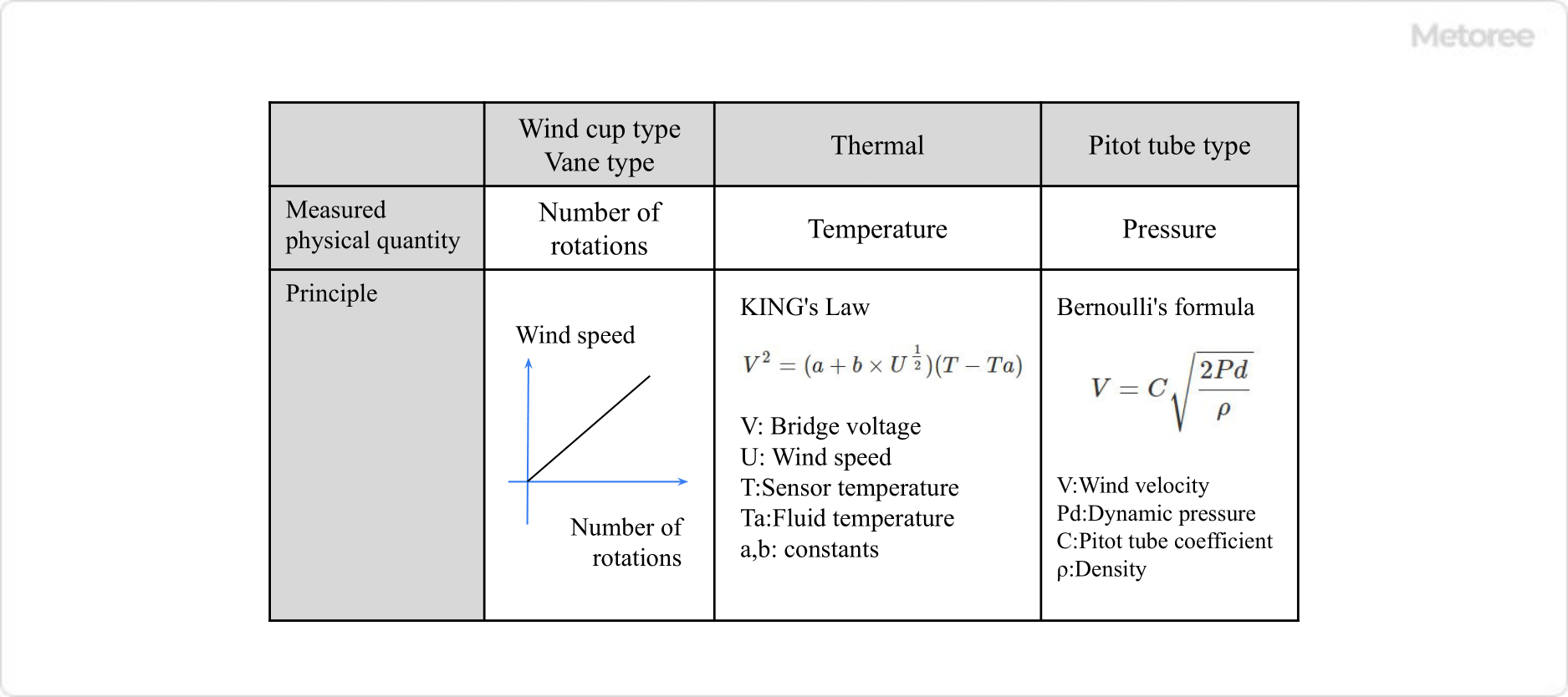
Figure 1. Principle of digital anemometer

There are several types of anemometers, but the most common types of small, portable digital anemometers are the hot-wire and vane (wing-wheel) anemometers. In addition, pitot tube and wind cup anemometers are also available.
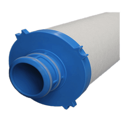
1. Hot-Wire Type

This is the most common type for indoor use. A resistive element whose resistance changes with heat is installed at the tip of the sensor, and when it receives wind, the sensor is cooled and the temperature of the hot wire decreases.

The faster the flow is, the faster the cooling is. Therefore, the resistive wind velocity is measured by utilizing the relationship between the flow velocity and the amount of cooling heat. This relationship is called the KING’s relationship. Accurate measurement is not possible outdoors because the temperature changes due to the heat of the sun and other factors.

This is a compact measuring instrument with a simple structure. It can also measure other characteristics such as wind temperature and humidity at the same time.

2. Vane Type

The measuring principle of the vane type wind sensor is to calculate the speed by measuring the number of rotations of the vane (impeller) rotating with the fluid. The principle is based on the principle that the number of rotations is proportional to the speed.

The rotational speed is largely independent of the density, pressure, and temperature of the fluid. The number of vane rotations is counted by a proximity switch or photocoupler.

Compared to the hot-wire type, it can be used outdoors because it is not affected by heat. However, it is not suitable for use when wind speed changes in small increments due to its lower accuracy in the low wind range and slower response speed.

2682_Digital-Anemometers_デジタル風速計-2.png

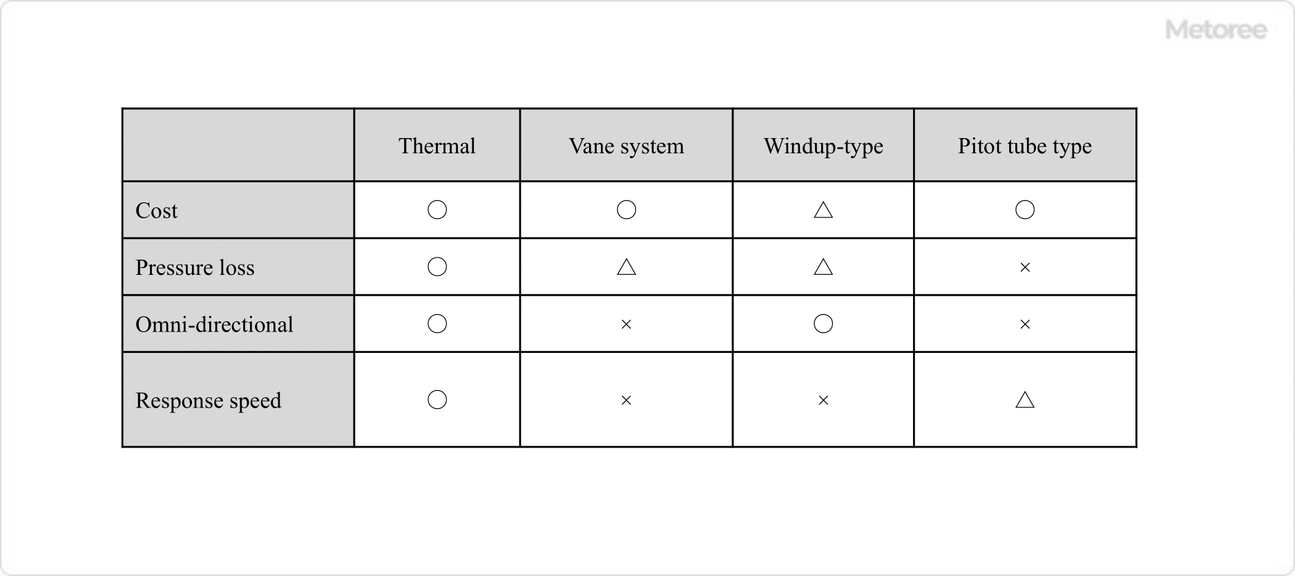
Figure 2. Types of digital anemometers

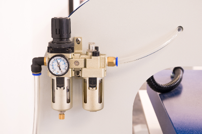
3. Pitot Tube Anemometer

Pitot tube anemometers are often used in industrial applications. Pitot tube anemometers measure wind speed from Bernoulli’s theorem by measuring the pressure difference between small holes in front of and to the side of the air flow. Accurate velocities cannot be obtained unless they are oriented perpendicular to the air flow, but they are often inexpensive because of their simple principle.

4. Wind Cup Wind Velocity Sensor

The wind cup, which is shaped like a cup, rotates using the fact that the wind pressure on its front side and back side differs depending on the strength of the wind. Wind speed is measured by measuring the number of rotations. Because of the rotating motion, the response to changes in wind speed is slow, and it is not suitable for measurements in the low wind speed range.

Because of these differences in principle and characteristics, it is necessary to select the appropriate type of anemometer according to the purpose and application.

Other Information on Digital Anemometers

Advantages of Digital Anemometer

2682_Digital-Anemometers_デジタル風速計-3.png

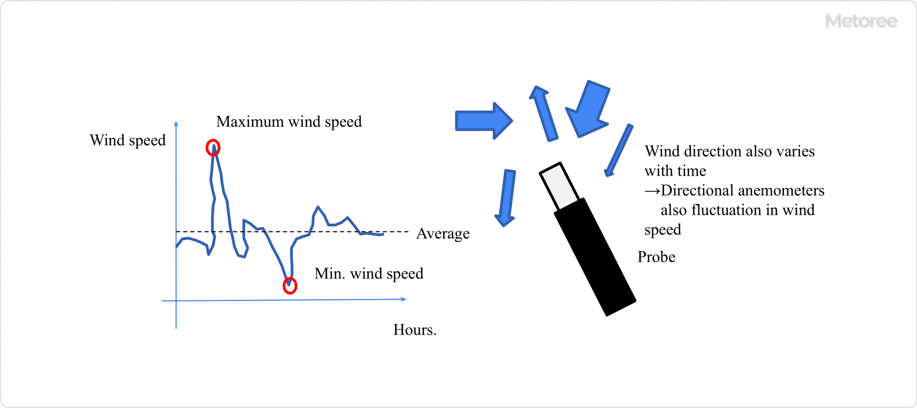
Figure 3. Temporal variation of wind speed and direction

The advantage of using a digital anemometer is that it automates the measurement of average, maximum, and minimum wind speeds. Normally, wind speed fluctuates greatly with time. Furthermore, since wind speed often varies with direction, even the direction of the anemometer probe can affect the accuracy, and hand vibration can change the value.

Even when average wind speed is desired, if the value fluctuates, it is difficult to obtain accurate data that does not involve subjectivity. The display unit of a digital anemometer is equipped with functions to calculate the average wind speed during these 00 seconds and to display the maximum and minimum wind speeds during these 00 seconds, etc., so that fair data can be obtained no matter who handles it.