カテゴリー
category_usa

Laser Rangefinders

What Is a Laser Rangefinder?

Laser Rangefinders

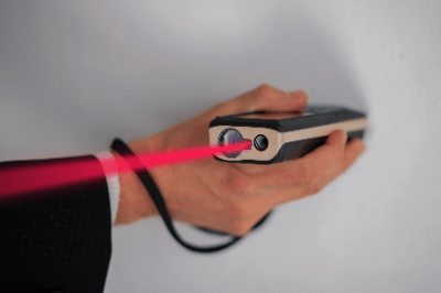
A laser rangefinder is a device that measures distance using laser light. These handheld tools are widely used in various fields such as construction, civil engineering, fishing, and forestry.

Laser rangefinders are prized for their high accuracy and contactless measurement capability. Some models offer precision up to ±1.0 mm. However, measurement accuracy can be affected by strong ambient light or surfaces with rough textures.

Uses of Laser Distance Meters

Laser distance meters have diverse applications:

1. Sports

These devices are integral in sports like athletics, cricket, and golf for measuring distances. In golf, for instance, they help golfers measure distances to fairways and greens for better club selection and shot strategy.

2. Civil Engineering and Construction

In construction and real estate, laser rangefinders accurately measure building dimensions and land areas. They are also vital in civil engineering for surveying terrain, and calculating elevations, and slope angles.

3. Fishing and Hunting

In fishing, they assist in measuring distances to shore for berthing and tide level assessment. Hunters use them to gauge distances to prey, adjusting shooting distance and trajectory accordingly.

Principle of Laser Rangefinders

Laser rangefinders measure distance by emitting a laser beam toward an object and detecting the reflected light. A photodetector inside the device captures the reflected light, measuring the time difference between emission and reception. This time difference, combined with the known speed of light, is used to calculate the distance to the object.

Types of Laser Distance Meters

Laser distance meters generally use the pulse method or the phase detection method:

1. Pulse Method

This method involves emitting a short light pulse and measuring the time taken for the light to reflect from the object. Suitable for long distances, it can measure several hundred meters to kilometers but becomes less accurate over longer distances.

2. Phase Detection Method

This method uses continuous wave light to measure distance by detecting phase differences. It provides high accuracy for shorter distances, typically tens to hundreds of meters, and is ideal for real-time measurements and tracking moving objects.

カテゴリー
category_usa

Laser Welding Machines

What Is a Laser Welding Machine?

A laser welding machine is a device that uses laser beams to weld two objects together. They are mainly used for bonding resins, utilizing the heat generated by their laser beam. Other welding methods include those using a heat plate and ultrasonic waves, all of which use the generated heat to melt the object and bond it when it cools. When the melted parts dissipate heat, they connect the boundary parts and cool and solidify. This is a clean device that can bond even the smallest of parts and does not generate any dust during the bonding process.

Applications of Laser Welding Machines

Laser welding machines are used for products that require a clean appearance and high-water resistance.

An example is car tail lamps. Tail lamps need to emit a beautiful light in an easy-to-see color. However, if plastic parts are joined together using screws or adhesives, the lamps will not look good. This is where laser welding machines can be used to create a beautiful finish without the use of adhesives.

Laser welding machines are also used for bonding products that require high waterproof performance, such as medical tanks. Since no screws or adhesives are used, the products are highly waterproof and less likely to deteriorate over time.

Principles of Laser Welding Machines

Laser welding machines bond objects together by melting the resin with a laser beam. First, a resin that transmits laser light and a resin that absorbs laser light are prepared. Next, the transmissive resin is placed on top and the absorbent resin is placed on the bottom, and the laser beam is applied from above. The light penetrates the transmissive resin and is continuously irradiated onto the surface of the absorptive resin, causing the interface between the two to generate heat. This heating causes the resin to melt, resulting in welding. Once melted, the resin cools and hardens when the laser is stopped, and the two resins are bonded together.

However, this method cannot be used for all types of resins, as both permeable and absorbent resins must be prepared. If both resins are permeable or absorbent, laser welding machines will be difficult to use. Basically, resins with high transmittance are white or transparent, and resins with high absorption are almost black.

The solution is to apply a laser absorbing agent to the underlying resin when the resins are white or transparent to each other. The absorbent will prevent the laser light from passing through the underlying resin, so the welding can be done in the same way as the normal method. In the case of black-on-black resin, the upper resin is welded using a permeable resin that is similar to black.

カテゴリー
category_usa

Ring Blowers

What Is a Ring Blower?

A ring blower is a type of blower, which is a compact device designed to generate high air pressure.

It is particularly well-suited for industrial applications requiring relatively low flow rates of 10 m3 or less. Due to its compact size, it is commonly integrated into industrial machinery and equipment.

The term “Ring Blower” is a registered trademark of Teral Corporation and was previously manufactured by Fuji Electric Co. Although they are often referred to as vortex blowers, the widely distributed ring blowers have become a household name. Another well-known name for this type of blower is the vortex blower (Hitachi Industrial Equipment Systems), which operates on a nearly identical mechanism.

Uses of Ring Blowers

Blowers come in a wide range of types, each with unique characteristics such as air volume and air pressure, depending on their operational principles and mechanisms. Ring Blowers are known for their ability to maintain high air pressure even at lower air volumes.

Given these characteristics, ring blowers find applications in various industries, including but not limited to the following:

  • Air supply and exhaust
  • Blowing off water droplets and adherent materials
  • Pneumatic conveying of powders and granules through suction or pressure feed
  • Paper feeding and material conveyance through adsorption, such as in paper handling

Principles of Ring Blowers

Ring blowers consist of a casing housing numerous impellers, and from the outside, they resemble a ring-shaped casing attached to a motor. The gap between the casing and the impeller is relatively small, and intake and exhaust ports are located near the casing’s periphery.

While turbo blowers and axial fans direct air uniformly in the flow direction, ring blowers create a more complex airflow pattern.

Centrifugal force propels air out of the impeller, causing it to strike the casing, rebound, enter the next impeller, and form a series of whirlpools. During this process, air pressure continues to rise. This repeated increase in pressure earns it the nickname “regenerative blower.”

Additionally, turbulence occurs due to the movement of numerous impellers within the narrow casing, further increasing pressure through momentum transfer. The combination of these effects allows ring blowers to achieve high air pressure in a compact design.

However, the small blade size and narrow flow path make ring blowers less suitable for handling large volumes of air. For applications requiring high flow rates at relatively low pressures, roots type blowers and turbo blowers are more appropriate choices. Equipment selection should align with the intended purpose, making ring blowers better suited for pressure-assisted conveying and handling tasks rather than simple air conveying.

カテゴリー
category_usa

Pipe Bending


What Is Pipe Bending?

Pipe Bendings

Pipe bending is a processing method that uses a processing machine called a “bender” to process parts by bending metal pipes.

Various metals such as copper, aluminum, iron, and stainless steel can be processed depending on the application. It is mainly used to process parts for automobiles and piping components.

Since “benders” are now available at home centers, more and more people are purchasing them for their personal use and performing pipe bending.

Uses of Pipe Bending

Metal pipe parts used in familiar items such as piping for various types of equipment, automobile mufflers, and pipe chair legs are made using this processing method. Generally, most of them are made of materials such as “aluminum,” “copper,” “iron,” and “stainless steel,” but metals such as “titanium” and “brass” can also be processed.

Also, the cross-sectional shape of pipes is not limited to the often seen circular shape but can be processed in a variety of cross-sectional shapes such as square and oval. However, there are limits to the shapes that can be processed depending on the shape of the pipe and the combination of materials, so it is necessary to consider the best combination for each application.

Principle of Pipe Bending

The following are some of the important elements of pipe bending. These elements are common to all of the typical bending shapes shown below.

  1. Tensile stress
    This is stress that occurs in the direction of pulling on the outside of the bent section. This causes the outside of the pipe to decrease in thickness and in some cases to become slightly concave.
  2. Compressive stress
    Contrary to tensile stress, this stress occurs in the direction of inward crushing. This can cause wrinkles on the inside.
  3. Inside Bending R
    This is the inside bending radius when bending a pipe. If this is made smaller, the tensile stress in (1) will increase and the outside will crack, or the compressive stress in (2) may cause wrinkles on the inside. Care should be taken especially with soft materials such as aluminum, as they are prone to wrinkling.
  4. Minimum Bending R
    The smallest inner bending R value within which the pipe will not crack. If bending is attempted with a radius smaller than this value, cracking will occur. Since there are differences depending on the material, plate thickness, shape, etc., care must be taken when considering processing.
    There is a countermeasure to prevent cracking by using annealing materials.

Typical bending shapes are introduced below.

  • Acute angle bending
    Bending at an angle of less than 90°.
  • L-shape bending
    Bending at a right angle like an “L”. In this process, it is necessary to pay attention to the phenomenon called “springback,” in which the angle opens back a little more than the angle at the time of bending. Aluminum, in particular, has high elastic deformation, so it needs to be bent extra large compared to other metals.
  • Obtuse angle bending
    This is a method of bending at an angle narrower than a right angle (about 95° to 175°), like the letter “L”. It is sometimes called “V-shape bending” depending on the item.
  • U-shape bending
    This is a method of bending 180° like the letter “U”. In this process, the beginning of both sides are bent first, and then the center part is bent. This process has the advantage of preventing contact with the die and making it easier to produce symmetrical products.
  • Box-shape bending
    This is a method of bending in the shape of the letter “U”. The L-shape bending described above is performed twice, and since the L-shape bending is performed twice, it is more difficult to obtain a more accurate angle than the L-shape bending.
  • Z-shape bending
    This is a method of bending in the shape of the letter “Z”. Even if the line is not diagonal like a perfect “Z,” it is still called a Z-shape bend.

By combining the various bending processes described above and joining multiple parts that have been bent together by welding or other means, a desired shape can be achieved.
Although individual processing is possible, there are limits to individual processing for high-precision processing and extremely thick or thin pipes, so it is necessary to request a specialized manufacturer depending on the specific application.

カテゴリー
category_usa

Metal Cutting Shears

What Is Metal Cutting Shears?

Metal cutting shears is a general term for scissors and cutters used to cut metal materials. There are two types of metal cutters: manual hand scissors and air metal cutters, which are electrically operated by connecting a compressor or other power source.

Depending on the cutting application, the main body of the shears may be equipped with an optional auxiliary fixture, a two-blade metal cutter for achieving clean cutting surfaces, or a hole-punching nibbler cutter.

Inexpensive hand-scissors type cutters are available in the range starting from 1,000 yen and offer a wide variety of options. They can cut not only metal materials but also thick wool and surface tatami mats.

Uses of Metal Cutting Shears

The primary use of metal cutters is to cut steel and aluminum sheets. Electric air metal cutters can even cut very thick metal sheets, making them indispensable tools for building material processing. They produce beautifully finished cross sections on the cut surface, even with materials like galvalume corrugated sheets.

These cutters can also be used to cut not only metal and light metal sheets but also vinyl chloride sheets, carpets, and various other materials. They are also valuable as cutting tools for remodeling and hobby crafts. Furthermore, they are frequently used for three-dimensional fabrication of relatively soft metal materials such as aluminum and copper sheets.

Principles of Metal Cutting Shears

The long handles of manual type shears allow for easy application of force using the principle of leverage, making it possible to cut thin steel sheets. The fixed blade, which has a base supporting both ends of the shears, enables you to exert pressure on just one end of the handle and push the shears through thicker copper plates.

The length of the shears affects the amount of force required for cutting. Therefore, shorter blades with pedestals are more efficient for one-person work.

When working with materials of unreasonable thickness or curvature, it is recommended to use metal cutting shears with two cutting edges.

Electric metal cutting shears create two cutting lines, allowing you to cut both ends of the plate beautifully when splitting it. A notable feature of this two-blade-tip metal cutter is that it produces spiral tape dust when cutting.

Electric metal cutting shears, also known as nibbler cutters, can make holes in metal sheets by replacing the pointed end rods and can reproduce free curves in continuous cutting. Cordless hand-grip types are commercially available for complex tasks and are popular for their lightweight feel. The cutting edge is made of steel or ultra-hard alloy, and the tool is easy to maintain except for chipping.

カテゴリー
category_usa

Mini Vises

What Is a Mini Vise?

A mini vise is the smallest type of vise. “Vises” are tools used to hold workpieces in place during operations and are used in various machining operations. Mini vises are mainly used for manual processing and can be purchased at 100-yen stores. Vises themselves are made of a wide range of materials, from metal to resin, and each material has different holding power.

Uses of Mini Vises

Mini vises are used to secure objects during processes such as sanding and cutting. Although not necessary if the work can be done by hand, they are indispensable when work cannot be performed by hand, such as when working with high-speed rotating equipment. Since the vise only holds the workpiece itself, it must be firmly attached to the worktable using screws or clamps during actual use. Mini vises are the smaller of the two and are mainly used for manual processing.

Principle of Mini Vises

Both “vises” and “mini vises” consist of a mechanism that achieves linear motion by turning a screw and secures an object by clamping it from both sides. Since fixation is performed by the tightening force of the screw, care must be taken not to damage soft objects when fixing them. Generally, there are metal vises and resin vises, and the choice of “metal vises for metal processing” and “resin vises for resin processing” is often made based on the material of the vises when securing the object. Some metal vises have a “V-groove” carved on the surface to secure stick-shaped objects more effectively.

In addition, vises typically have holes or long holes for fastening, which are used to secure the object to the processing table with screws. If fastening with screws is not possible, a separate clamp may be used. This is because if the vise itself is not secured, the entire workpiece may move with the vise during operation. This is particularly crucial when working with high-speed rotating objects such as drills and routers, as there is a high risk of unexpected injury.

カテゴリー
category_usa

Pipe Rack System

What Is a Pipe Rack System?

A pipe rack system refers to a series of products that can be combined with pipes, joints, and special parts to create various products such as racks and carts.

Pipes include painted pipes, stainless steel, and aluminum, and parts such as metal joints, plastic joints, plastic conveyors, and casters.

Assembly requires no special tools or knowledge, allowing the user’s ideas to be implemented on their own.

Once created, the system can be reassembled and changed to other equipment, making it possible to accommodate changes in production lines.

Uses for Pipe Rack Systems

In addition to racks such as picking racks and file racks, a wide range of items can be created, including wagons, work tables, PC work tables, shooters, conveyors, carts, and partitions.

We can also create products for special shapes and individual purposes, such as storage and transportation of long items, boards, and in-house standard products.

We can also make large products such as in-plant greenhouses, simple booths, and event booths.

In addition to production sites, the system can be used in a wide range of fields, including transport and conveyance sites, administrative departments, and sanitation fields.

Features of Pipe Rack Systems

Pipe rack systems are a series of products that can create racks, carts, and other products according to your needs by combining pipes special parts, and joints.

Pipes include coated pipes, stainless steel, aluminum, and resin-coated pipes, and joints include metal joints and plastic joints, which can be selected according to the application.

No special tools or knowledge are required, and anyone can create these products anywhere. Repairs and modifications after assembly can be easily made.

Since they can be created according to the work content, site, and user, they reduce waste of space and movement, and reduce unreasonable and wasteful movements, thereby improving work efficiency.

A wide variety of special parts are available, including plastic conveyors and casters, and by selecting the most suitable parts, it is possible to add inclines and change the number of steps, as well as reduce man-hours and labor by using a non-powered mechanism.

In addition to improving efficiency at production sites, such as elevating work tables and overhead opening/closing carts, they can also be applied to office furniture such as partitions and file racks.

カテゴリー
category_usa

Micro Relays

What Is a Micro Relay?

A micro relay is a compact device among relays, designed to switch electric circuits on and off in response to external signals. Smaller than typical relays, they range in size from a few centimeters to just a few millimeters, making them ideal for space-constrained applications such as control systems and electronic equipment.

Notable for their high-speed switching capability, micro relays are suitable for applications requiring rapid signal processing and timing control. They are reliable in operation and have a long service life. However, due to their small size, their current capacity is limited. For large current control, larger relays should be considered.

Uses of Micro Relays

Micro relays find applications in various fields:

1. Electronic Devices

In smartphones, they control circuits and are used for functions like camera auto-focus or speaker switching. Office automation equipment, like printers, also uses micro relays for controlling paper feed and cartridge positions.

2. Automobiles

Widely used in automobiles, these relays manage window operations, switch headlights, and control bright mode settings. Automobile door lock systems also depend on Micro Relays for locking and unlocking mechanisms.

3. Medical Equipment

In medical devices like electrocardiographs, micro relays are used to acquire and process signals. They also play a role in sphygmomanometers, helping to control pressure sensors and switch display devices.

Micro Relay Principle

Comprising a coil, contacts, and springs, micro relays are enclosed in a resin or other insulating material casing for protection.

1. Coil

These relays often use electromagnetic coils made from thin conducting wires that generate a magnetic field to operate the contacts when electrified.

2. Contact Point

Contacts, made of electrically conductive metals like gold, silver, and copper, control the electrical flow.

3. Spring

Springs in micro relays apply the necessary pressure to the contacts, ensuring reliable switching between open and closed states.

How to Select a Micro Relay

When selecting a micro relay, consider the following:

1. Coil Voltage

Choose a micro relay with a coil voltage that matches your system’s operational voltage, ranging from low voltage options like 3.3 VDC or 5 VDC to higher voltage models at 12VDC or 24VDC. Select relays with built-in protection diodes to handle back EMF currents that could affect other devices.

2. Contact Current

Assess the contact current, the maximum current that the relay can handle. Due to their compact size, most micro relays have a low current rating, typically 2A or less. Exceeding this rating can cause contact welding or other malfunctions.

3. Connection Method

Micro relays can be integrated into circuits through various methods. Socket connections using pins are common, but there are also surface-mountable products.

4. Number of Poles and Contact Configuration

Consider the number of poles (number of contacts) and contact configurations, which include a-contact (normally open), b-contact (normally closed), and c-contact (a combination of the two).

カテゴリー
category_usa

Pneumatic Balancer

What Is a Pneumatic Balancer?

A Pneumatic Balancer is a device for handling heavy objects.

It is a device that assists the operator in lifting, turning, and moving heavy objects, and is sometimes called a balancer or hand crane.

Pneumatic Balancers are usually fixed to the floor or ceiling and do not operate unless external force is applied. Pneumatic Balancers can be moved within their range of motion by grasping the handle and applying light force in the desired direction.

Since the operator does not need to exert much force when lifting heavy objects, the operator can move heavy objects as if handling a lightweight object.

Uses of Pneumatic Balancers

Pneumatic Balancers are often used at workplaces where handling heavy objects is difficult with large equipment such as cranes and inverters, or when automation with robot arms or other devices would be dangerous to workers.

They are used at sites with a lot of human traffic because they do not operate when no external force is applied, and they do not perform active movements other than those intended by the worker.

There is also a type of Pneumatic Balancer that can be mounted on a ceiling rail, which is useful for transporting heavy objects over long distances while they are being lifted.

Principle of Pneumatic Balancers

Variable force, etc., can be set by air pressure for the air type and by electric power for the electric type.

In the air type, the air cylinder works to counteract the weight of the workpiece, allowing the operator to move the workpiece without being aware of its weight.

1. Pneumatic Principle

Balance is taken by the air cylinder and air control circuit. The pilot regulator adjusts the pressure in the air cylinder according to the load, no load, or vertical movement of the arm to maintain the necessary pressure for balancing.

Once balanced, the workpiece can be moved freely.

2. Automatic Weight Sensing Control

When a load is lifted, the balance is automatically switched from no-load to load by feeding back the cylinder internal pressure to the control circuit.

This makes it possible to handle loads of different weights at random.

3. Pressure Control

By setting the pressure for load and no-load in advance, the pressure can be switched and balanced.

This control is effective for continuous transfer of the same weight.

4. Interlock Control

Some models can be fitted with attachments. More advanced functions can be realized by interlocking the attachment operation with the main unit control.

Functions that enhance workability and safety can be implemented, such as automatically balancing the load when the attachment is held, or locking the attachment while the load is balanced.

Types of Pneumatic Balancers

Pneumatic Balancers are broadly classified into three categories: installation method, driving method, and degree of freedom, each of which is different from the others.

1. Installation Method

For installation, there are floor-mounted types, ceiling-fixed types, and types that are mounted on ceiling rails. The choice should be made in consideration of the installation range and the range of movement.

2. Driving Method

There are two types of drive methods: pneumatic and electric. The pneumatic type can be used simply by connecting high-pressure air, while the electric type has the advantages of support force setting and complex control.

Another advantage of the pneumatic type is that it is safe, as it does not generate motor heat or sparks.

Both drive methods are equipped with a function to hold a heavy object in the same position when the operator removes his/her hand from the supported object. There is also a drive method called hybrid barraman that combines air and electricity.

3. Degree of Freedom

There are two types of freedom: 1-axis and 2-axis types. 1-axis type has a doughnut-shaped movable area because it simply swivels around the installation position, while 2-axis type has a circular movable area because its height can be adjusted by bending its arm.

Pneumatic Balancer also offers a variety of attachments for various applications, such as those with vacuum suction, fork-shaped attachments, and attachments with a reversing mechanism.

カテゴリー
category_usa

Micro Motors

What Ia a Micro Motor?

Micro Motor

A micro motor is a very small electric motor, typically with an output of 3 watts or less. These motors can be as small as a millimeter in size, making them ideal for integration into constrained spaces and microscopic systems.

Micro motors are crucial in the design of miniature devices and modules, particularly in industries requiring advanced technology like medical precision equipment and various automotive components.

Advancements in microelectromechanical systems (MEMS) and nanotechnology are leading to smaller, more powerful micro motors, enhancing their capabilities as microscopic power sources for complex tasks.

Uses of Micro Motors

Micro motors have a broad range of applications, including:

1. Medical Equipment

Used in devices like endoscopes, surgical robots, and dental handpieces, micro motors enable precise movements. Dental handpiece motors, for example, can operate at speeds ranging from 100 to 40,000 rpm.

2. Electronic Devices

These motors are integral to smartphones (as vibration motors), fitness bands, and smartwatches, providing functionalities like notifications and vibration alerts. Most micro motors in these applications are DC motors for battery compatibility.

3. Automobiles

Micro motors automate the retraction and deployment of external mirrors in vehicles, aiding in reducing vehicle width and preventing mirror damage during parking. They are also used for adjusting the position and angle of automobile seats.

Principle of Micro Motors

Micro motors operate similarly to typical DC motors. They consist of a coil (winding of conductive wire) that forms a magnetic field when an electric current passes through it. This interaction generates the Lorentz force, causing the coil to rotate. The current direction, magnetic field direction, and generated force direction are orthogonal, allowing precise control of rotation and force in micro motors.

They have two primary components: the rotor (with the current-carrying coil) and the stator (providing a fixed magnetic field). The interaction between the rotor’s coils and the stator’s magnetic field produces rotary motion.

Types of Micro Motors

Micro motors come in various types, including brushless and permanent magnet DC motors:

1. Brushless Motor</h4

Brushless motors are DC motors without electrical brushes, known for efficiency and reliability. They typically have three or more coils, and rotation is controlled by sequentially supplying current to these coils.

Characterized by compact size, high efficiency, long lifespan, and low maintenance, brushless motors come in two types: inner rotor and outer rotor. The inner rotor type offers better controllability, while the outer rotor type provides stable rotation.

2. Permanent Magnet DC Motor

This motor type features an internal permanent magnet and uses brushes for rotation, with the brushes supplying current to the coils. Known for simplicity, cost-effectiveness, and ease of control, these motors are sometimes replaced by brushless motors due to the wear and maintenance of brushes.

Permanent magnet DC motors are further classified into surface magnet and embedded magnet types. The surface magnet type attaches magnets to the rotor’s outer circumference, whereas the embedded magnet type embeds magnets inside the rotor.