カテゴリー
category_usa

Pin Socket

What Is a Pin Socket?

A pin socket is an electrical component designed as a female terminal for connection with pins, often used in conjunction with pin headers. These sockets align with the regularly spaced pins on headers, typically with a pitch of 2.54 mm or 2.5 mm, and are manufactured to match this pitch.

Pin sockets, which can be soldered to PCBs, provide an easy way to establish terminal connections for pin headers, facilitating the connection between PCBs, sensor boards, modules, and microcontrollers.

Uses of Pin Sockets

Pin sockets are selected based on the pitch and pin count of the corresponding pin headers. As pin headers vary in PIN, pin sockets can be cut or modified to accommodate the required number of pins. This versatility makes them suitable for interconnecting PCBs, sensor boards, and modules, and linking microcontrollers to their modules. They can also be used with jumper wires of appropriate diameters and socket sizes.

Principle of Pin Sockets

Pin sockets function by providing electrical continuity when jumper wires or pin headers are inserted. However, compatibility in wire diameter and length with the socket dimensions is crucial. If the socket is too deep or shallow, it can lead to poor conductivity or loose connections, respectively.

While pin sockets allow for easy connection and disconnection of multiple contacts, it’s important to be mindful of their orientation during insertion. Incorrect orientation can lead to improper connections, so designing circuits to be orientation-independent or implementing physical orientation constraints is advisable.

Additionally, caution is necessary when soldering pin sockets for module connections. The heat from a soldering iron can be transferred to the module, potentially causing damage. Experienced soldering technicians might mitigate this risk by soldering quickly and efficiently with the pin headers inserted.

カテゴリー
category_usa

Pirani Vacuum Gauge

What Is a Pirani Vacuum Gauge?

A Pirani vacuum gauge is a sensor that measures vacuum levels using the piezoelectric effect. It is often used in various situations due to its small size, portability, and ease of operation. In this device, the current flowing to the measuring element changes according to the vacuum level, enabling the measurement of vacuum levels. Generally, a Pirani gauge consists of a controller and a measuring element, covering a range from about 0.5kPa to 2kPa.

Though Pirani gauges have limitations in accuracy at lower ranges, they can operate from atmospheric pressure to vacuum without concerns of breakage. Some models feature a separable measuring element and controller.

Uses for Pirani Vacuum Gauges

Pirani gauges are commonly used in fluid circuits where vacuum reach control is crucial, such as in chambers and quartz tubes, and in applications requiring surface cleanliness. They are particularly effective in the medium vacuum range, achievable with oil-rotary vacuum pumps. These gauges are also used in high vacuum to ultra-high vacuum pumping systems, medical instruments, analyzers, semiconductor manufacturing, and electron microscopes.

However, calibration is necessary for accurate absolute pressure measurements, as the indicated value varies with the type and composition of the gas.

Principle of the Pirani Vacuum Gauges

Pirani gauges function by measuring the thermal energy dissipation when gas impinges on a heated platinum wire. The pressure is inferred from the current value required to maintain the wire’s temperature. The platinum wire inside the gauge is heated to about 200 degrees Celsius. When air contacts the wire, it cools it down, requiring more power to maintain the temperature. Conversely, in a vacuum, less power is needed to keep the wire heated. The power change indicates the vacuum level.

Regular maintenance of the platinum wire is vital for accuracy. Over time, the wire wears out and requires more power to reach 200°C, necessitating periodic replacement and cleaning to avoid dust adhesion.

Other Information on Vacuum Gauges

Definition of Vacuum

Vacuum levels are classified into low, medium, high, and ultra-high vacuum, with Pirani gauges effectively measuring from low to medium vacuum. According to JIS standards, vacuum levels are categorized as follows:

  • Low vacuum: 105Pa to 102Pa
  • Medium vacuum: 102Pa to 10-1Pa
  • High vacuum: 10-1Pa to 10-5Pa
  • Ultra-high vacuum: 10-5Pa to 10-8Pa
  • Extremely high vacuum: 10-8Pa or less
カテゴリー
category_usa

Piezo Stage

What Is a Piezo Stage?

The piezoelectric effect is the deformation of certain crystals or ceramics when a voltage is applied. Stages that utilize this phenomenon for precise linear motion, rotation, or other positional changes are known as piezo stages.

Piezo stages are highly valued in scientific research and industrial applications for their nanometer-order fine movement, position resolution, precise position reproducibility, and the ability to integrate with encoders for accurate feedback systems.

Uses of Piezo Stages

Characterized by their fine movement, high position resolution, and precise reproducibility, piezo stages are used for:

  • Linear motion stages
  • Rotation stages
  • Scales and tipping stages
  • Precise equipment movement and positioning
  • Vibration isolation systems
  • High-speed precision shutter systems

These applications span across scientific research and industrial fields.

Principle of Piezo Stages

Piezo stages are based on the piezoelectric effect, where specific types of ceramics deform in response to applied voltage. The deformation correlates with the voltage, is reversible, and responds extremely quickly.

Piezo actuators, formed from piezo elements, are used as positioning mechanisms in these stages. Unlike conventional motor-driven stages, piezo stages offer high position resolution and repeatability, efficient load handling with low power, and rapid response, making them ideal for applications requiring precise and fast positioning.

Advantageous for their non-reliance on magnets, piezo stages are unaffected by magnetic fields and do not disrupt their surroundings. They are also suitable for vacuum environments.

However, larger movements necessitate additional mechanical support, and the heat generated by the piezo element, as well as its temperature-dependent deformation, must be considered.

カテゴリー
category_usa

Vickers Hardness Tester

What Is a Vickers Hardness Tester?

Vickers Hardness Testers A Vickers hardness tester is a hardness tester that evaluates hardness based on the indentation left by a diamond indenter. This tester measures the diagonals of the indentation after pressing the indenter into the test material with a specified load.

Unlike the Brinell hardness tester, which uses a 10 mm iron ball indenter, the Vickers tester utilizes a diamond square with a 136° angle, allowing for precise measurement of the indentation on the test surface.

Uses of Vickers Hardness Testers

Vickers hardness testing is mainly used to evaluate the hardness of metallic materials, particularly suitable for small-range hardness assessments like heat-treated layers, the depth of these layers, and thin materials.

The Vickers test is effective for shallow depth evaluations because of its small test load. For example, assessing the hardness of carburized and quenched steel materials, where a large test load could press the indenter deeper than the hardened layer, making an accurate assessment difficult.

Principle of Vickers Hardness Testers

Vickers testers are versatile, allowing for arbitrary selection of test loads for accurate evaluation regardless of the test object’s thickness. Using a diamond square indenter, the Vickers test creates a small indentation, measured using a metal microscope.

By selecting the appropriate test load, the Vickers test can evaluate the hardness of thin specimens or surface treatments without the indentation penetrating the hardened layer. Specimen requirements for Vickers testing include surface flatness, parallelism, and roughness, typically prepared by polishing to a mirror-like finish.

Other Information About Vickers Hardness Testers

1. Difference Between Vickers and Rockwell Hardness Testers

Rockwell hardness testers, like Vickers, measure hardness by indenting the material but differ in indenter shape and measurement method. Vickers testers use a square pyramid diamond, while Rockwell testers use a spherical indenter. Vickers measures diagonal width, while Rockwell measures indentation depth.

Rockwell testers are quicker and more suitable for metallic materials at production sites but require different indenters and test conditions based on hardness. Vickers testers use the same indenter for different loads and provide consistent results regardless of load variation.

Vickers and Rockwell hardness values can be converted using standard tables.

2. Automatic Mechanism of Vickers Hardness Testers

Modern Vickers testers often include automatic mechanisms for measuring hardness at multiple points, particularly useful for carburized or welded parts with varying hardness. These systems can measure across a range of points and display hardness values as a gradation map, providing detailed information for development and troubleshooting.

カテゴリー
category_usa

Power Lock

What Is a Power Lock?

Power Locks

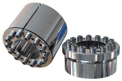
A Power Lock is a friction-type fastener mainly used to fasten a shaft and a boss.

Power Lock uses the wedge principle to obtain frictional force and is characterized by its ability to fasten two parts with non-backlash by simply tightening the bolt. Backlash refers to the play caused by the meshing of gears, while non-backlash refers to the absence of play in the gears.

Uses of Power Locks

Power Lock is used to fasten mechanical elements such as rotating shafts, pulleys, and gears in various industrial machines. They are also used in semiconductor manufacturing devices and food processing machines. The characteristics of wear-type fastening devices are mainly used in fields such as conveying, packaging, and printing machinery.

In these applications, the phase level can be adjusted with only one bolt, for example, for final positioning of powertrain components such as pulleys and sprockets. In addition, the design requires less space because the adjustment can be made from the side of the rotating parts. We also offer an environmentally resistant series to meet the needs of clean rooms.

Principles of Power Locks

The outer ring and inner ring, which are in contact with each other on the tapered surface, are spread over the inner and outer diameters by the fastening bolt, creating a frictional force between the shaft parts and housing parts.

Some hydro-hydraulic systems are based on Pascal’s principle. In the hydro-hydraulic system, a screw pressurizes and compresses the pressure medium sealed inside the sleeve to generate a frictional force between the shaft parts and housing parts.

Features of Power Lock

Frictional fasteners using wedges, such as Power Lock, are characterized by their low cost and versatility. On the other hand, they require time and labor for installation and dismounting.

Hydro-hydraulic systems are slightly more expensive than wedge mechanical systems, but they are very easy to maintain, and their ease of installation and removal, as well as their speed and precision, are also advantages of hydro-hydraulic systems. The wedge-mechanical system is relatively compact but can handle high torques.

However, because of the large number of screws used, removal takes a lot of time, and care must be taken not to forget to tighten the screws. In contrast, the hydro-hydraulic system is easier to install and remove, more accurate, and superior to the mechanical system if cost is not a factor.

Other Information about Power Locks

1. Tightening Torque of Power Locks

Power Lock transmits torque by friction with the shaft. To achieve the specified transmission torque, the tightening torque of the tightening bolt and the dimensional tolerance of the shaft must be controlled.

The tightening torque for bolts is listed in the manufacturer’s technical data and ranges from 11.1 to 18.4 Nm for a shaft diameter of 20 mm, which varies from model to model. The transmission torque at this time is 61.7 to 62.7 Nm. The recommended tolerance of the shaft dimensions is h6 for φ38 or smaller and h8 for φ40 or larger, and if the dimensions are too small, the transmission torque will be reduced. Conversely, if the dimension is too large, mounting will not be possible.

Tighten the bolts diagonally and gradually to ensure uniform tightening. Finally, set the torque wrench to the specified torque and tighten all bolts. This prevents over-tightening.

Although multiple Power Locks can be installed on a single shaft, it should be noted that the transmitted torque is not simply proportional to the quantity. According to the manufacturer’s data, the torque is 1.55 times higher with two locks and 1.85 times higher with three locks. 

2. How to Remove the Power Lock

When removing Power Lock, loosen the pressurizing bolt to release the tightening by the wedge. However, some power locks that have been tightened for a long period of time may be stuck and cannot be simply removed by loosening the bolts. In this case, screw the bolt into the extraction tap next to the pressurized bolt hole and forcibly pull off the fastener.

It must also be ensured that no load or torque is applied to the Power Lock during removal. If the Power Lock pops out or rotates during removal, it may cause a serious accident.
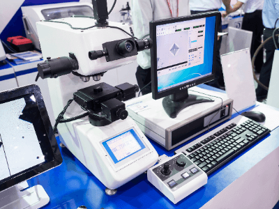
カテゴリー
category_usa

Power Conditioner

What Is a Power Conditioner?

Power Conditioners 
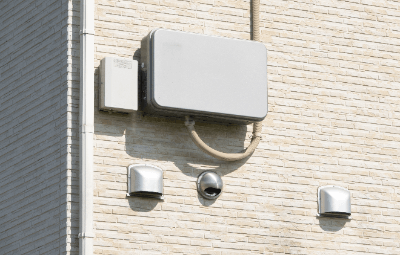
A power conditioner is an inverter that converts the power generated by solar panels into commercial AC power. It also plays a key role in the system control of solar power generation.

Key functions include:

  • Efficiency maximization in power generation
  • Grid connection and disconnection control with the power utility

This latter function helps prevent issues like spillover accidents in case of system malfunctions. The efficiency of a power conditioner is indicated by its conversion efficiency, typically around 95%.

Uses of Power Conditioners

Power conditioners are essential in solar power generation systems, used in both industrial and private roof-mounted installations. They manage the connection and disconnection to the power grid and can serve as emergency power sources when paired with batteries, operating independently during disasters or power outages.

Principle of Power Conditioners

Power conditioners transform DC power from photovoltaic sources into AC power, compatible with electric utility transmission. Their components include:

  • DC/DC Circuit: Stabilizes the power from the solar panels.
  • DC/AC Circuit: Converts the stabilized DC power into AC power by rapidly switching polarity.
  • Shutdown Circuit: Safeguards the system from spillover during abnormalities.

Post-conversion, the AC power is fed into the distribution board for use. Power conditioners also regulate current and voltage to optimize solar power utilization, adjusting to varying weather and sunlight conditions.

Other Information on Power Conditioners

1. Life Span of Power Conditioners

The lifespan of power conditioners, typically 10 to 15 years, is shorter than that of solar panels due to wear and deterioration of components like cooling fans. Regular maintenance, including filter cleaning and lubrication, can extend their service life.

2. Failure of Power Conditioners

Failures can stem from poor installation connections, aging and heat, or external environmental factors. Examples include cable faults due to poor connections, component wear, or damage from rain, animals, and insects. Preventative measures include thorough installation management and sealing against environmental intrusions.

カテゴリー
category_usa

High Power LED

What Is a High Power LED?

A high power LED, standing for “light-emitting diode,” is an LED variant characterized by a higher power output. Due to their high luminous efficiency, high power LEDs have become a prominent component in various lighting solutions.

These LEDs are composed of multiple LED elements arranged in parallel. They require a substantial current to drive but offer high luminance. Compared to standard LEDs, high power LEDs share similar internal parts but are distinguished by their heat-dissipating structures.

Uses of High Power LEDs

High power LEDs are widely used in lighting applications and as indicator lamps. Their typical uses include:

  • Automobile headlights
  • Large floodlights for outdoor stadiums
  • Ceiling lights in factories and residences
  • Fish-collecting lights on fishing boats

High power LEDs are integral to both industrial and consumer products, making them a crucial part of daily life.

Principle of High Power LEDs

High power LEDs function on the basic principle of light emission in diodes. When current flows through the diode’s P-type and N-type semiconductors, light is emitted at their junction. High power LEDs achieve higher output by connecting multiple LEDs in parallel.

Due to their large current requirements and consequent heat generation, high power LEDs are designed with efficient cooling systems. Approximately 70% of their energy is released as heat, necessitating heat sinks or heat-dissipating boards for effective cooling.

Other Information on High Power LEDs

1. Difference Between High Power LEDs and Ordinary LEDs

The primary difference between high power and ordinary LEDs lies in their output power. LEDs with an output of 1W or more are typically classified as high power LEDs. Despite having similar LED chips, high power LEDs require a specialized heat dissipation structure.

2. Driving Method of High Power LEDs

For efficient operation, high power LEDs are best driven by a constant-current circuit rather than a simple current-limiting resistor, which would increase power consumption and heat generation. Using components like FETs and operational amplifiers, a constant-current light emission can be achieved. Additionally, the board’s heat dissipation design is crucial for stable operation.

3. Package of High Power LEDs

High power LEDs are available in various packages, including:

  • Surface Mount Type: Offers design flexibility, often used when designing optical lenses.
  • COB (Chip On Board): A common high power LED package, combining the substrate and LED chips for easy installation and wiring.
  • Cannonball Shape: Designed for enhanced directivity, suitable when a focused light emission is desired.
カテゴリー
category_usa

Pallet Stage

What Is a Pallet Stage?

A pallet stage is a mezzanine-type rack system, designed as a temporary mezzanine to utilize the often underused space above warehouse areas. Unique for their installation process, these systems do not require anchoring to the building, allowing for quick assembly and disassembly.

Similar structures include stacking racks, stacking shelves, mezzanine-type stacking racks, mezzanine racks, three-dimensional racks, and plain racks. The pallet stage, in particular, employs a simple installation method by using reverse nestainers (reverse nesting racks) as supports and is installed without the need for anchors.

Uses of Pallet Stages

Pallet stages are primarily designed to maximize the use of dead space above warehouses. By creating a double-layered flat surface, they effectively double the workspace and storage capacity.

These stages are advantageous because they do not require bolts for installation. They can be easily set up with a forklift, moved, or modified as needed. When not in use, they can be disassembled and stored compactly. The design also allows for aesthetic enhancement of the space.

Rental services for pallet stages, including installation, are also available from some providers.

Features of Pallet Stages

Pallet stages can be assembled and disassembled more quickly and easily compared to other mezzanine structures, like laminated and mezzanine types, due to their no-weld, no-anchor design. They offer flexibility in expansion or contraction to match inventory needs and are space-efficient when stored.

Recently, mezzanine racks, including pallet stages, have been reclassified from simple “racks” to a category of buildings, especially in the context of earthquake resistance. This shift means that their design and construction may need to adhere to fire safety regulations and earthquake resistance standards. Moreover, additional lighting may be required under these structures to compensate for reduced illumination.

It’s important to note that the upper floors of pallet stages are not designed for occupancy. They cannot be used as office spaces but are intended solely for loading and storing cargo.

カテゴリー
category_usa

Hammer Lock

What Is a Hammer Lock?

A hammer lock is a specialized stopper device designed for carts that do not come equipped with a standard stopper. It’s an alternative to traditional caster stoppers and is often customized for specific cart models. The hammer lock mechanism can be engaged or disengaged by stepping on a lever with the foot.

Installing a hammer lock typically requires modifications to the cart’s main body, hence they are considered custom-ordered products. Different types of hammer locks are available to suit various load conditions, and their installation enhances the functionality of caster stoppers. For added durability and rust resistance, hammer locks are also available in stainless steel.

Uses of Hammer Locks

Hammer locks are particularly useful for carts and carriers lacking built-in stoppers. By attaching these external locks, they effectively function as stoppers, enabling the user to secure the cart in place. The lock is usually located near the cart’s wheels and is foot-operated.

Given the daily use of dollies and carts at work sites, the absence of a stopper can pose safety risks, especially if a loaded cart begins to move unexpectedly. Therefore, hammer locks serve as crucial safety features for carts without inherent stopper mechanisms.

Principle of Hammer Locks

The locking mechanism of hammer locks operates by lifting the wheels slightly off the ground and gripping the cart to the floor, thereby immobilizing it. Proper installation requires aligning the lock with the specified mounting height. Additionally, depending on the height of the casters, a pedestal might be needed for height adjustment under the cart bed.

When using carts with hammer locks, it’s important to consider floor level differences, as uneven surfaces may prevent the lock from functioning correctly. Therefore, selecting equipment suitable for the specific work environment is essential. It’s also important to note that hammer locks are not designed for lifting purposes and should not replace a jack. Furthermore, since they are often made of rubber, they should not be used with grounding clips or to secure work platforms or steps.

カテゴリー
category_usa

Hammer Crusher

What Is a Hammer Crusher?

Hammer Crushers
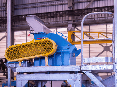
A Hammer Crusher is a crushing machine that crushes large objects using a hammer.

The object is gradually crushed by a hammer rotating at high speed, and the input object is reduced in size. They are used in diverse fields, such as ore, food materials, and chemical products. The shape of the hammer and rotation speed can be adjusted according to the object.

Although the crushing capacity is high, it is not capable of crushing finely, so other equipment must be used together as needed. Also, because of its low installation cost, it is sometimes used as a relatively simple device.

Uses of Hammer Crushers

Hammer Crushers are used in a wide variety of applications in the industrial, food, and medical industries.

In industrial uses, they are widely used for crushing and processing mineral resources such as ore, limestone, and gypsum.

They are also used for the temporary crushing of food and chemical products. For example, lumpy food products used as raw materials can be fed into hammer crushers to be crushed to a certain size before proceeding to the manufacturing process.

In the case of chemical products, crushing to a certain size may be necessary in the process of research and development or experimentation.

Although it is possible to adjust the shape of the hammer and rotation speed according to the object, it is impossible to crush it into a fine powder. Therefore, other types of crushers must be used if microscopic powder form is desired.

Because of their high crushing capacity and low installation cost, hammer crushers are widely used in rock mining, construction sites, and other situations where crushing of relatively large objects is required.

Principle of Hammer Crushers

Hammer Crushers operate on the simple principle that a high-speed rotating hammer crushes an object by striking it hard. The hammers come in various sizes and shapes, and can be installed according to the object to be crushed for efficient crushing. In addition, objects can be crushed more efficiently by bouncing off the plate or by being destroyed by the impact of being struck.

In addition, a mesh-like device called a rosle is installed at the outlet to sort crushed objects. It is also possible to crush them into specified sizes. Since the size of crushed objects can be adjusted according to the application, the system is used in a variety of fields.

Another advantage is the low cost of installation and simple structure, which reduces the possibility of breakage or malfunction. On the other hand, vibration and noise caused by high-speed rotating hammers may occur, requiring consideration of the surrounding environment.

Types of Hammer Crushers

There are two main types of hammer crushers in general use: single-rotor hammer crushers and double-rotor hammer crushers.

Some are made of wear-resistant materials, some are equipped with a cooling system, and some have a special structure for handling large objects. Depending on the application, it is necessary to select the hammer crusher to be used.

1. Single-Rotor Hammer Crusher

The single-rotor type hammer crusher has a number of hammers attached to a single rotor. Objects are fed into the rotor and crushed by the hard hitting of the hammers. It is suitable for crushing large objects, and its advantage is that it can process large quantities at a time.

2. Double-Rotor Hammer Crusher

The double-rotor type hammer crusher has hammers attached to two rotors. Objects are crushed between the two rotors. It is suitable for processing small objects at a time and provides more even crushing.