カテゴリー
category_usa

Pipe Adapter

What Is a Pipe Adapter?

Pipe Adapters

A pipe adapter is used to extend pipes, connect pipes of different diameters, and create curves and branches.

When selecting a pipe adapter, the following points should be considered: the shape of the adapter, the type of thread, the diameter of the adapter, and the material.

The type and diameter of the threads affect the tightness of the connection. Connecting different types of screws to each other is a safety factor because it can cause leakage.

The material must be carefully selected, especially when acids, bases, or organic solvents are transferred in the piping. Select an appropriate material so that the pipe adapter will not be corroded and leakage will not occur at the connection.

Uses of Pipe Adapters

When piping to transport liquids or gases, there are cases where the piping may be extended, the thickness may be changed in the middle, or curves or branches may be added. Pipe adapters are useful in such situations to adjust the pipe structure.

The following are some examples of situations in which they can be used:

  • When it becomes necessary to extend pipes due to changes in the plant layout, pipe adapters with the same inner diameter as the pipes can be used to extend the pipes.
  • When laying a water pipe along a wall, 90° curved pipe adapters are used to connect pipes in order to curve the pipe to fit the corner of the wall.
  • When transferring liquid from tank A to two tanks B1 and B2, branch the pipes coming out of tank A with a three-way adapter and connect one to tank B1 and the other to tank B2.
  • To connect pipes A and B with different diameters, one adapter should be connected to pipe A and the other to pipe B with the same inner diameter.

Features of Pipe Adapters

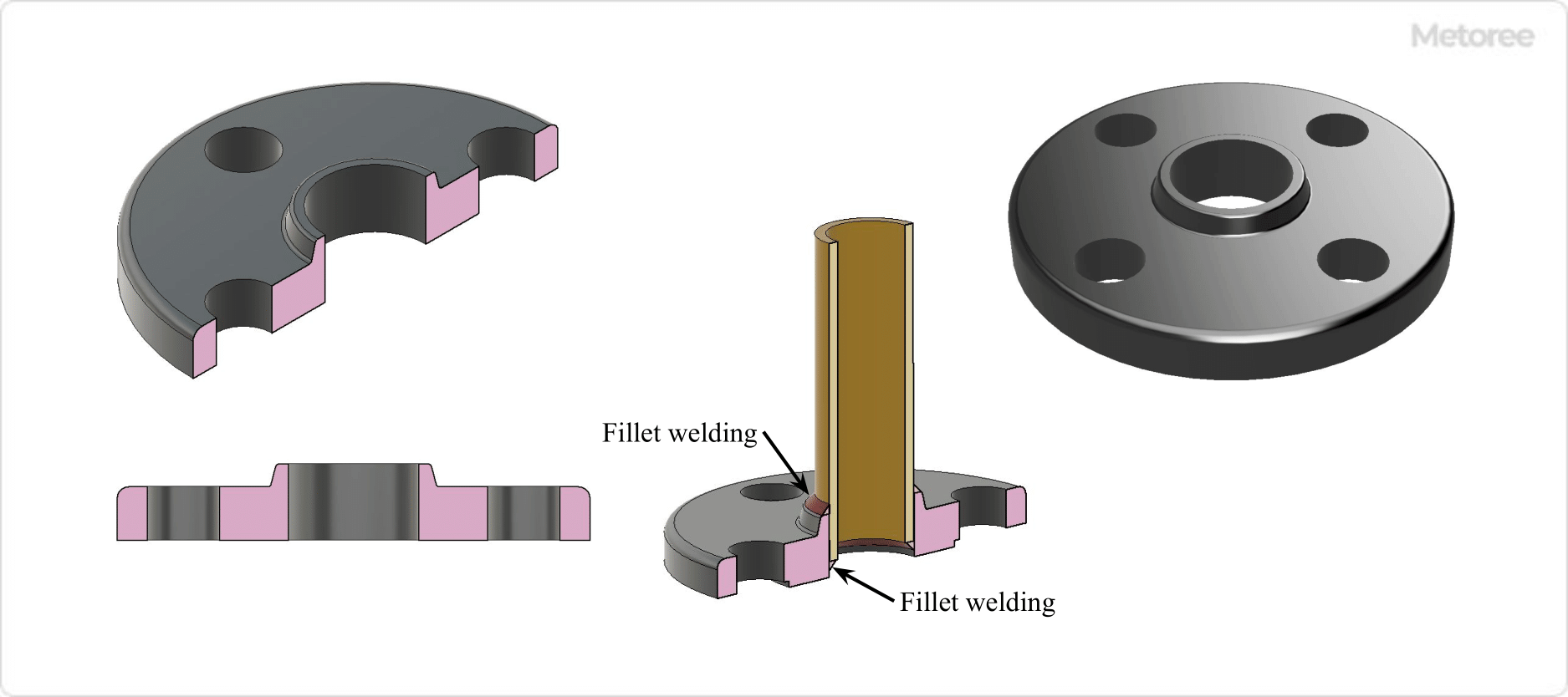
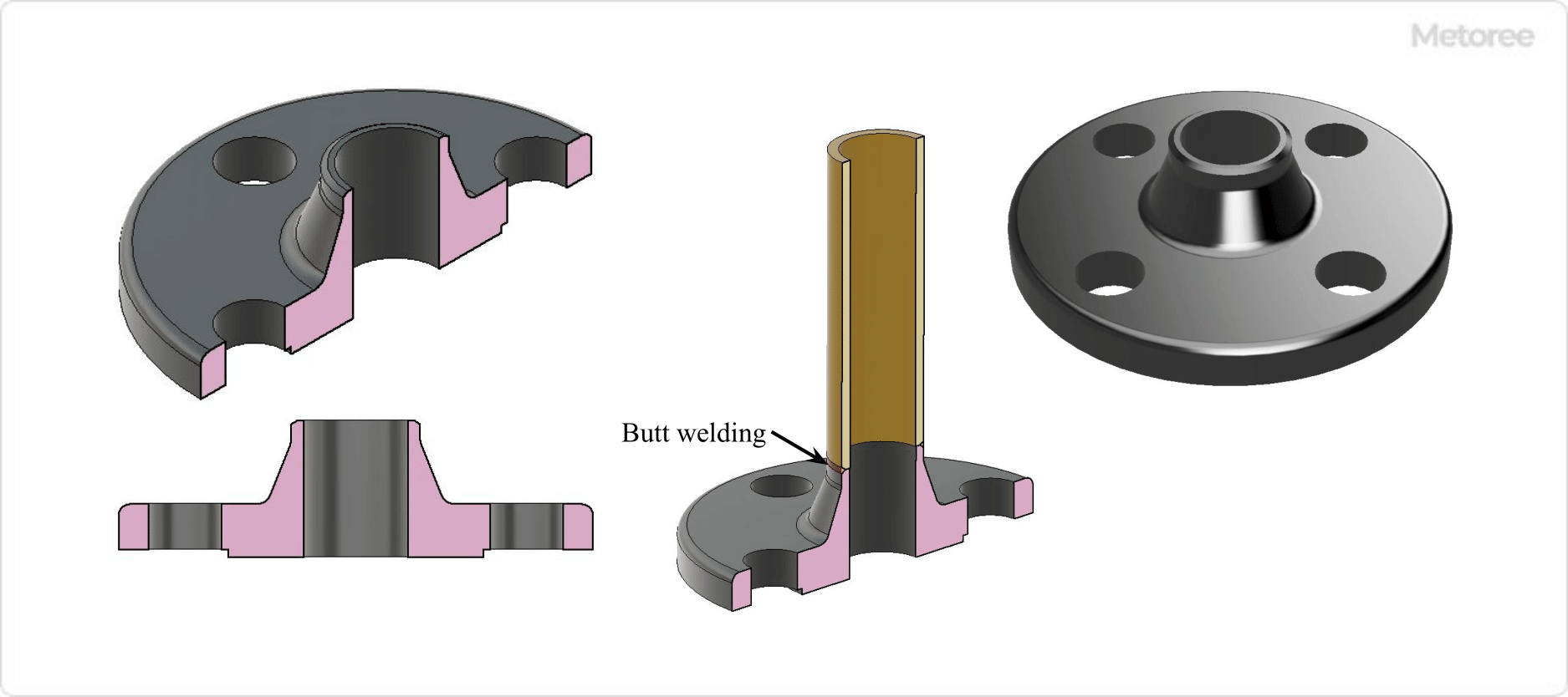
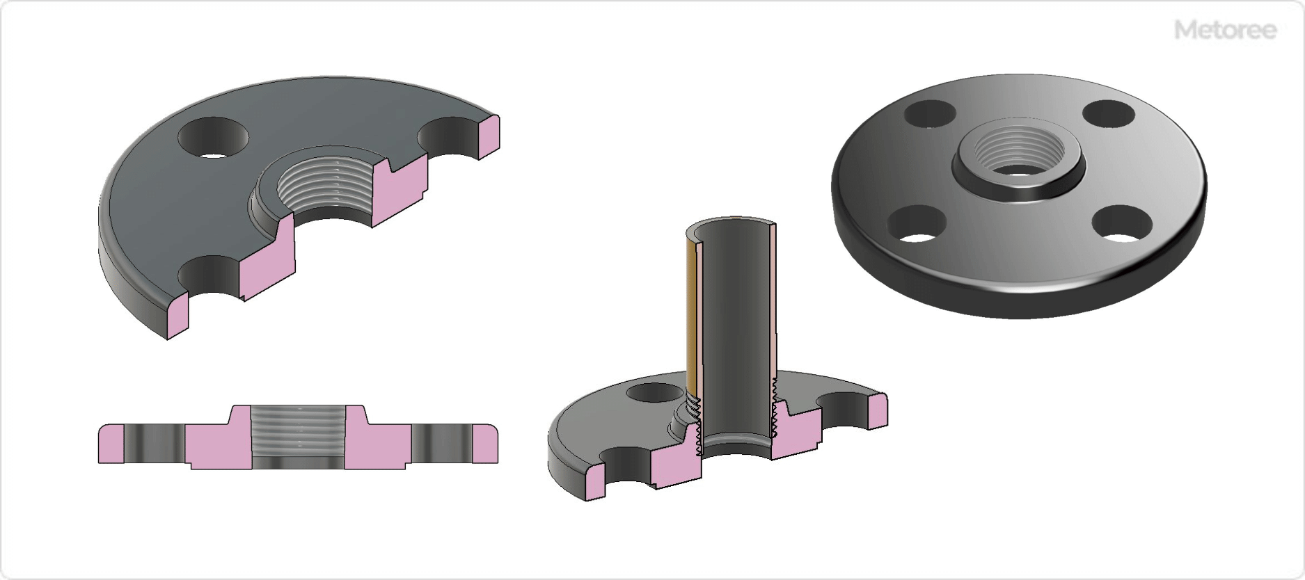
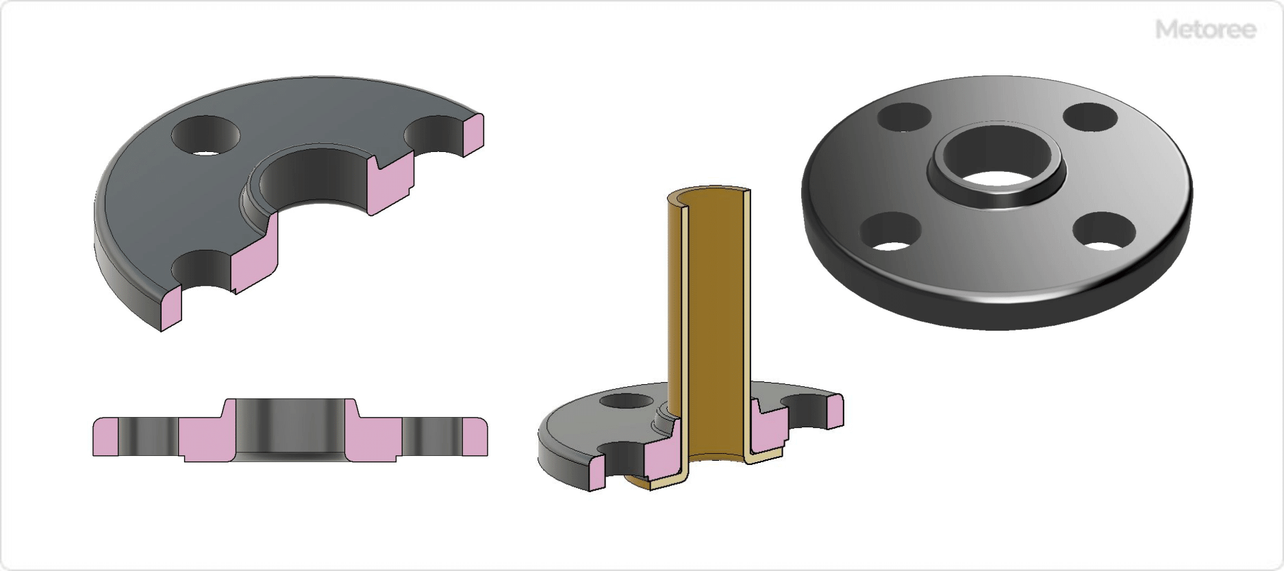
Attach a male or female thread to the piping to be connected, and attach a sealant to the male thread to prevent leakage. Then, connect and fix the pipe and the pipe adapters.

In selecting pipe adapters, the following points should be carefully checked:

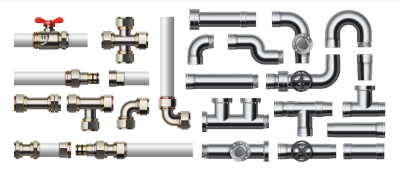
  • Shape of the adapter
    Select a straight adapter if the pipes are to be connected in a straight line, a branched adapter if the pipes are to be branched, or a curved adapter (90° is common) if the pipes are to be curved.
  • Screw type
    Check for the proper combination of male and female screws. In addition, there are standards for “tapered threads for Kan” and “parallel threads for Kan,” and connecting tapered threads for Kan with parallel threads for Kan may result in leakage. Refer to the following to select an adapter so that the type of pipe and pipe adapter threads match:
  • Tapered pipe threads are tapered toward the end and are characterized by their high liquid-tightness and airtightness; in ISO standards, male threads are indicated by “R” and female threads by “Rc”.
  • Parallel pipe threads are uniform in thickness from root to tip and are designated “G” for both male and female threads in ISO standards.
  • Adapter Diameter
    In the catalog, the diameter of the adapter’s connection is written. For example, if it says “inner diameter D (Φmm): 6”, it means that the inner diameter of the adapter connection is 6 mm in diameter. Make sure that the diameter of the adapter matches that of the pipes to be connected before making a selection.
  • Material
    SUS, aluminum, PVC, and polypropylene are used as materials for pipe adapters. When transporting acids, alkalis, organic solvents, etc. inside a pipe, it is easy to overlook the resistance of the adapter; be sure to check whether the material used can withstand the liquid to be transferred, for example, SUS is corroded by strong acids, polypropylene is soluble in some solvents, etc.
カテゴリー
category_usa

Pipe Flange

What Is a Pipe Flange?

Pipe Flanges

A pipe flange is a flat component attached to a pipe or equipment, serving as a type of pipe fitting.

Used for both pipe-to-pipe and equipment-to-pipe connections, pipe flanges are essential for various joint types. While some flanges are specifically designed for non-pipe connections, they are commonly referred to simply as “flanges.”

One key advantage of pipe flanges is their ease of disassembly for maintenance, offering high sealing performance. By loosening the bolts and nuts, the joint can be easily separated for internal cleaning and inspection, a process not feasible with welded pipe constructions without cutting.

Uses of Pipe Flanges

Figure 1. Example of pipe flange use

Figure 1: Example of Pipe Flange Use

Pipe flanges are utilized across a wide range of piping systems, transporting fluids such as air, gases, water, chemicals, food, steam, oil, and more. Their ability to be reused and ensure a high degree of sealing makes them preferable for applications in ships, railroads, and industrial settings, especially under extreme conditions like high or low temperatures, high pressure, or vacuum.

Principle of Pipe Flanges

Typically, pipe flanges connect by placing a gasket (sealing material) between two flanges and securing them with bolts and nuts. This method applies both to pipe-to-pipe and equipment-to-pipe connections, enhancing the joint’s sealing ability.

Figure 2. Joining pipe flange (Assembly)

Figure 2: Joining Pipe Flanges (Assembly)

The gasket improves the seal between flange surfaces and varies in type depending on the fluid’s temperature and pressure.

Types of Pipe Flanges

Various standards outline steel pipe flanges, classified by shape, fluid pressure, connection method, and gasket type. Selecting the appropriate flange type is crucial for the specific application.

1. Slip-Welded Flange (SOH)

Figure 3. Insertion-welded flange (SOH)

Figure 3: Slip-Welded Flange (SOH)

This common type involves inserting a pipe into the flange hole and welding it at both the top and bottom, securing the connection.

2. Socket-Welded Flange (SW)

Figure 4. Socket-welded flange (SW)

Figure 4: Socket-Welded Flange (SW)

Socket-weld flanges are attached by inserting the pipe up to the flange’s back step and welding the outside surface to the top of the flange, accommodating thermal expansion.

3. Butt-Welded Flange (WN)

Figure 5. Butt-welded flange (WN)

Figure 5: Butt-Welded Flange (WN)

Preferred for larger diameters due to their strength, butt-welded flanges offer a reliable method of joining pipes.

4. Threaded Flange (TR)

Figure 6. Threaded flange (TR)

Figure 6: Threaded Flange (TR)

Threaded flanges screw onto the end of a pipe, suitable for low-pressure and temperature applications.

5. Loose-Joint Flange (LJ)

Figure 7. Loose-joint flange (LJ)

Figure 7: Loose Joint Flange (LJ)

Loose-joint flanges, or lap-joint flanges, facilitate easy orientation and installation with moderate sealing performance.

6. Blind Flange (BL)

Figure 8. Closing flange (BL)

Figure 8: Blocking Flange (BL)

Blind flanges seal the end of a pipe or temporarily close a flange without causing fluid leakage.

7. Mounting Flange (MF)

Figure 9. Mounting flange (MF)

Figure 9: Mounting Flange (MF)

Mounting flanges combine two different seating configurations for accurate alignment.

8. Groove Flange (TG)

Figure 10. Groove flange (TG)

Figure 10: Groove Flange (TG)

Groove flanges, comprising convex and concave pairs, are known for their excellent sealing properties.

How to Select a Pipe Flange

Selection is often based on the maximum working pressure and temperature of the fluid, using the appropriate standard for stress calculations and nominal pressure ratings.

Other Information on Pipe Flanges

Gaskets vary by type, each suitable for different conditions. Standards for pipe flanges include JIS, ANSI/ASME, and others, with JIS and JPI standards predominantly used in Japan.

カテゴリー
category_usa

Pneumatic Valve

What Is a Pneumatic Valve?

Pneumatic Valves

Pneumatic valves are devices that control air pressure in systems or use air pressure to operate actuators. This article focuses on pneumatic relief valves/safety valves and pneumatic actuators/pneumatic valves. Pneumatic relief valves are designed for compressed air systems, including air compressors, to safeguard against excessive pressure by releasing air when the system’s pressure approaches a critical level.

These valves are crucial for maintaining safe pressure levels in compressed air applications. Pneumatic actuators, on the other hand, are valves that utilize pneumatic force to switch between open or closed states, providing a simple, efficient way to manage airflow with significant driving force.

Uses of Pneumatic Valves

1. Pneumatic Relief Valve

Used in compressed air systems to regulate or release excessive pressure, pneumatic relief valves prevent potential damage to the compressor and other system components by mitigating pressure spikes. These valves are compact and can be easily integrated into the system through a threaded mounting port.

2. Pneumatic Actuator

Pneumatic actuators play a vital role in fluid handling systems by controlling the start and stop of flow using high-pressure air. They are pivotal in automating valve operation for efficient fluid management.

Principle of Pneumatic Valves

1. Pneumatic Relief Valve

The construction of a pneumatic relief valve includes a nozzle for air intake, a disc acting as a seal, and a spring to maintain pressure on the disc. The spring tension can be adjusted to set the air pressure threshold for safety. When the system pressure exceeds this threshold, the air pressure forces the disc up, allowing excess air to escape and reduce the pressure.

2. Pneumatic Actuators

Pneumatic actuators use high-pressure air to move valves for fluid control. The influx of high-pressure air moves internal cylinder components, translating this motion into valve operation via rack and pinion gears.

Other Information on Pneumatic Valves

1. Common Causes of Pneumatic Relief Valve Failure

Despite their reliability, pneumatic relief valves can fail due to dirt, wear, or damage to their components. Issues such as nozzle or disc damage can lead to air leakage at non-critical pressures. A compromised spring may fail to maintain the necessary pressure on the disc, resulting in unwanted air release.

2. Common Causes of Compressed Air System Failure

A malfunctioning pressure switch, rather than the pneumatic valve, often causes unexpected pressure issues in compressed air systems. The pressure switch regulates the operational pressure range of the compressor, and its failure can lead to air leakage. A professional inspection of the entire compressed air system is recommended to identify and rectify such issues.

カテゴリー
category_usa

Spherical Plain Bearing

What Is a Spherical Plain Bearing?

A spherical plain bearing is a type of bearing that supports both radial and axial loads in both directions.

This bearing consists of a spherical outer ring and a ball-shaped inner ring with a drilled hole. It offers an alignment function that allows for misalignment between the center of rotation of the shaft and the housing.

It is utilized in parts that require oscillating and alignment movements. “Rod end” and “rod end bearing” are terms sometimes used interchangeably with spherical plain bearings.

Uses of Spherical Plain Bearings

Figure 1. Applications of spherical plain bearings

Figure 1: Applications of Spherical Plain Bearings

Spherical plain bearings are primarily used for linking parts or transmitting linear motion. They find applications in the joint motion components of construction machinery, industrial machinery, automobiles, and aircraft, supporting oscillating or alignment motions.

These bearings can withstand large radial and thrust loads in both directions. They offer high resistance to impact loads and are commonly used in cylinder clevises, hinges of construction and civil engineering machinery, and truck suspensions.

A common application for spherical plain bearings is in rod ends (or rod end bearings).

Principle of Spherical Plain Bearings

The spherical plain bearing has an outer diameter of the inner ring (sliding contact surface) that is convex and an inner diameter of the outer ring (sliding contact surface) that is concave. A small clearance between their sliding contact surfaces ensures an appropriate sliding surface while providing alignment and load-bearing capabilities.

These bearings are suitable for supporting high static and dynamic loads at relatively low rotational speeds, with the alignment function facilitating easy centering and accommodation of misalignment.

Types of Spherical Plain Bearings

1. Classification by Structure

Figure 2. Types of spherical plain bearings by structure

Figure 2: Types of Spherical Plain Bearings by Structure

Lubricated Type
In the lubricated type, both the outer and inner rings are greased through lubrication holes to maintain optimal lubrication. The rings are made of high-carbon chromium-bearing steel for high wear resistance.

Lubrication-Free Type
The lubrication-free type does not require lubrication. The sliding surface of the outer ring is made from a material with high self-lubricating properties and excellent wear resistance. The inner ring consists of steel balls with surface treatments such as hard chrome plating, offering maintenance-free operation and exceptional wear resistance.

Figure 3. Shape of spherical plain bearings due to structural differences

Figure 3: Spherical Plain Bearing Geometry with and without Seals

With and Without Seals
Bearings with seals have seals at both ends between the inner and outer rings to prevent grease leakage and the intrusion of foreign matter. Bearings without seals are available for applications where seals are not necessary.

2. Radial and Thrust Loads

Spherical plain bearings are categorized into two types: those that support both radial and thrust loads, and those that support only thrust loads.

Figure 4. Other spherical plain bearings

Figure 4: Other Spherical Plain Bearings

3. Solid Lubricant Embedded Type

This type features an inner ring made of a special copper alloy with a solid lubricant embedded in the sliding surface, and an outer ring with a lubricating coating on the sliding surface.

4. Bearing Unit

Spherical plain bearing units are pillow-type units incorporating spherical plain bearings.

Other Information on Spherical Plain Bearings

Spherical plain bearings are defined as “plain bearings with a spherical contact surface designed primarily for oscillating, tilting, and low-speed rotational motions.”

The motions supported are defined as:

Oscillating Motion
A rotational or tilting motion in which the direction of motion is repeatedly reversed.

Tilting Motion
A motion in which the angle of inclination between the inner and outer rings of the bearing, or between the shaft raceway and housing raceway, changes relative to each other.

カテゴリー
category_usa

Directional Control Valve

What Is a Directional Control Valve?

Directional Control Valves

A directional control valve is a critical component in hydraulic systems, designed to control the flow direction of hydraulic oil within a circuit. It is instrumental in directing the movement of a cylinder or motor, dictating actions such as extension and retraction in cylinders, rotation in motors, and cloud dumping in gripping-type attachments.

There are several types of directional control valves, including check valves and solenoid-operated valves. The control of these valves can be mechanical, hydraulic, or electromagnetic, with solenoid types enhancing control convenience significantly.

Uses of Directional Control Valves

Directional control valves are vital in the construction machinery industry, regulating oil flow in various equipment like hydraulic excavators, bulldozers, and wheel loaders.

For hydraulic excavators, these valves manage the oil flow from a single hydraulic pump to different components like cylinders, motors, and attachments. They ensure precise control over machine movements by effectively distributing oil to the required actuators.

Principle of Directional Control Valves

This section outlines the principles of operation for the main types of directional control valves: check valves and directional valves.

  • Check Valves
    Comprising a poppet, spring, input, and output sections, check valves allow oil flow from input to output when the oil pressure exceeds the spring force. Conversely, no oil flows to the input when pressure is applied to the output, as the poppet blocks the flow.
  • Directional Valves
    A directional valve, consisting of a spool, input sections A and B, and output sections A and B, controls oil flow direction. For example, switching its direction affects the expansion or contraction of a connected cylinder.

In a neutral state, the spool blocks oil flow to the cylinder. When receiving a signal from input section A, the spool shifts, allowing high-pressure oil from output A to reach the cylinder, while return oil is channeled back to the reservoir through output B. The process is similar for signals from input section B, enabling bidirectional control of the cylinder.

カテゴリー
category_usa

Conveyor Chain

What Is a Conveyor Chain?

A conveyor chain is a machine used to transport loads by moving and circulating a row of chains by means of gears.

Generally, a double-chain system combining two chains is used to transport loads.

In addition, shallow rods, planks, buckets, and other devices are attached between the chains to facilitate transport.

This method is incorporated for conveyors used in situations where the lifting force is strong and the slope is steep. Bucket conveyors can also be used for vertical lifting.

Uses of Conveyor Chains

Conveyor chains are often used in the flow of work in factories.

Conveyor chains are used for conveying the products that are processed regularly in a conveyor system. Examples include distribution centers and agricultural cooperative centers that transport containers, food factories, and chemical plants that transport drums.

They have excellent characteristics in terms of strength and abrasion resistance and can be used in a wide range of applications by attaching various attachments.

Principle of Conveyor Chains

Conveyor chains are machines used to transport a load by moving and circulating a row of chains by means of gears.

The chain consists of two plates with rollers connected between them and a further plate connected to the outside of the rollers.

The connection between plates is connected by a bar structure called a bush, which serves as a bearing when the chain bends.

Chains are classified into three types according to the shape of the rollers: R roller type, F roller type, and S/M roller type.

1. R Roller Type

In the R roller type, the outer diameter of the rollers is larger than the width of the plate.

2. F Roller Type

The F-roller type has flanges attached to the rollers to serve as guide rails.

3. S and M Roller Type

On the other hand, the S-M roller type has rollers whose outer diameter is smaller than the width of the plate.

Chain materials include ordinary steel, carbon steel, and alloy steel. Chains may also be heat-treated to increase strength.

In addition to the chain material, attachments should be selected according to the intended use.

カテゴリー
category_usa

Exhaust Valve

What Is an Exhaust Valve?

An exhaust valve is installed as integral parts of a vehicle’s exhaust system and open and close to control gas flow, optimize engine backpressure, and improve performance and acoustic control.

The exhaust valve is located in the cylinder head of an internal combustion engine.

When the fuel/air mixture ignites in the cylinder, spent gases are pumped out of the engine through this valve.

In a typical internal combustion engine, the exhaust valve is larger than the intake valve.

This is because it is more difficult to clear the exhaust gases from the cylinders than it is to introduce fuel and air into the combustion chamber.

A key feature in building horsepower and fuel economy in modern engines is the ability to optimally time the opening and closing of the exhaust valve.

Uses for Exhaust Valves

The camshaft is at the center of control, grinding lobes to clear the cylinder to take full advantage of the valve’s capabilities.

By opening the exhaust valves at critical times in the combustion process, the piston is able to push all of the exhaust gases from the cylinder out of the combustion chamber without sacrificing the flow of intake charge into the cylinder.

Several factors are involved in assisting the exhaust valves.

Valve pockets in the cylinder head are very important.

Like exhaust valves, valve pockets and bowls must be unrestricted so that spent gases can exit the combustion chamber quickly and without restriction.

The exhaust port must also be free of obstructions, and gasket matching is a common way to accomplish this.

Principle of Exhaust Valves

By grinding the exhaust ports and exhaust manifold of the cylinder head to the same size as the openings in the exhaust gasket, the gases do not contact the blunt edges of the gasket or exhaust manifold and impede flow.

This smooth transition eliminates backpressure that would otherwise impede the flow of exhaust from the engine.

Smoothing the radius of the exhaust bowl in the cylinder head also aids flow by providing a smooth unobstructed path for flow out of the cylinder.

When grinding the valve seat of an exhaust valves, six different angles can be ground on a single valve face for high-performance applications.

Each angle corresponds to an existing angle ground into the valve seat of the cylinder head.

The engagement of the angles not only provides a proper seal when the valve is closed, but also provides a smooth path around the edge of the valve for gas to flow.

In a typical street vehicle, exhaust velocity is not as critical as in a racing engine, so a three-angle valve grind is used.

Exhaust Valve Construction

Exhaust valves are used in sealed vessels and piping, for example, to prevent destruction when internal pressure rises.

The basic structure of an exhaust valves are that when the internal pressure rises, the valve body or ball section is pushed up and the valve opens to vent the internal pressure to the outside. After the pressure is discharged, the valve is no longer pushed up by the pressure, so the valve drops under its own weight to stop discharging pressure.

Until now, exhaust valves has not been seen very often in daily life. Recently, however, we are seeing more and more masks with exhaust valves in factories and other places. When working with a mask, humidity and temperature inside the mask rise, making it difficult to breathe. When breathing in, the valve is pulled closed by negative pressure. Conversely, when you exhale, the valve is pushed open by exhalation, expelling the humidity and heat inside.

Exhaust valves are not included in safety valves or air vent valves when divided by genre or category. But they are similar in that they vent internal pressure.

Safety valves are intended to prevent serious accidents such as rupture or destruction of equipment or structures due to pressure buildup. Safety valves work by releasing pressure to the outside when a set pressure is reached in an enclosed container or piping.

Air vent valves prevent air from mixing with water or other fluids. To give an example, if air gets mixed in with a pump for fluid, the propeller that generates the water flow will spin out of control and be damaged. To prevent this phenomenon, known as air biting, air vent valves use the pressure of the fluid that flows into the air vent valve to push up the valve to expel the air remaining inside.

Structure of Intake and Exhaust Valves

Intake and exhaust valves are valves that incorporate a gas intake structure into an exhaust valves. By being able to perform intake as well as exhaust, the valve can be used against negative pressure. When no negative pressure is generated, the operation is the same as that of an air vent valve. However, when negative pressure is generated, the valve can take in gas through the air intake port to break the vacuum.

In general, the structure is such that under atmospheric pressure, the gas is discharged by the operation of a float. When the inlet side where fluid flows in becomes negative pressure, the float operates to open a space for a valve such as a disk or diaphragm to operate. The valve then operates to take in the gas and relieve the negative pressure.


カテゴリー
category_usa

Manual Valve

What Is a Manual Valve?

Manual Valves

A manual valve (manual operated valve, hand-operated valve) is a valve that opens, closes, or adjusts its degree of opening by human operation (manual operation).

Manual valves are generally classified as globe valves, ball valves, gate valves, butterfly valves, or diaphragm valves, depending on their construction. Valves are used to shut off, “flow”, or “stop” fluids by opening or closing a flow path, and to regulate the flow rate.

Uses of Manual Valves

Figure 1. Example of manual valve use

Figure 1. Example of manual valve use

Manual valves are used to shut off fluid or regulate flow and pressure. When shutting off fluid, ball or gate valves are used. Typically, a ball valve is used because it is structurally stronger, leaves no valve plug (ball or disc) in the flow path, and can be opened and closed easily.

Neither of these valves can be used in the mid-open position. Care must be taken because cavitation will occur if the valve is used with the valve plug not fully opened at the halfway position.

Cavitation is a phenomenon in which a liquid becomes low pressure and vaporizes, generating bubbles. Cavitation causes increased vibration, noise, and flow pulsation, and may result in damage to piping and equipment.

Globe valves or butterfly valves are used to adjust flow and pressure. Globe valves are generally used because they are easy to adjust flow and pressure by operating the handle. However, globe valves have an intricate flow path inside the valve box (body), resulting in a large fluid pressure loss.

Principle of Manual Valves

A manual valve has a valve plug (ball, disk, etc.) inside the valve housing (body), and by turning the valve plug up and down, the plug adheres to the seat in the valve housing to shut off the flow path. Manual valves are manually operated to raise, lower, and rotate the valve plug.

The pressure drop across the valve as the fluid passes through the valve varies depending on the valve construction. Pressure drop is an important factor in valve selection. The pressure loss is calculated using the following Fanning’s equation:

ΔP=4f (ρμ2L/2d)

ΔP: pressure loss (Pa), f: friction coefficient, ρ: density of fluid (kg/m3), μ: average velocity of fluid (m/sec), L: pipe length (m), d: inner diameter of inner pipe (m)

Types of Manual Valves

There are several types of manual valves, depending on their construction and function. When selecting a manual valve, it is important to consider the type of fluid used (water, steam, air, gas, chemical, etc.), the pressure and temperature of the fluid, whether it is corrosive or not, and the purpose of use (shut-off, flow, pressure control, etc.).

1. Globe Valve

Figure 2. Globe valve

Figure 2. Globe valve

Globe valves are also called globe valves. They are used as stop valves or throttle valves because of their superior ability to shut off fluids and regulate flow and pressure.

The valve box (body) is rounded and the internal flow path is curved. The valve plug (disk) inside the valve box moves up and down by rotating a handle attached to the valve stem.

This causes the valve plug to contact the seat, shutting off the fluid. The distance between the plug and the seat varies with the degree to which the handle is rotated, allowing for flow and pressure adjustment. Used as valves to adjust the volume of utilities such as steam, cooling water, hot water, compressed air, and vacuum lines that require flow and pressure adjustment.

2. Ball Valve

Figure 3. Ball valve

Figure 3. Ball valve

Ball valves are characterized by the spherical (ball-shaped) plug (disc) inside the valve housing (body). The valve plug is rotated by turning the handle attached to the valve stem 90 degrees to shut off the flow path. Ball valves have a small pressure drop because the valve plug does not remain in the flow path when the valve is open.

Basically, they are not used in mid-opening and are not used for flow or pressure adjustment. They are relatively compact and inexpensive, and are often used as small stop valves because they can be closed simply by turning the handle 90 degrees.

3. Gate Valve

Figure 4. Gate valve

Figure 4. Gate valve

Gate valves are valves used specifically to shut off fluids. The valve plug (disc) inside the valve box (body) moves up and down by rotating a handle attached to the valve stem (stem).

This causes the valve plug to contact the seat and shut off the fluid. The flow path in the valve housing is straight, resulting in a small pressure drop. Used as a stop valve because it is not used in the middle opening position, but in the open-and-closed positions. 

4. Butterfly Valve

Figure 5. Butterfly valve

Figure 5. Butterfly valve

Butterfly valves are characterized by the disk-shaped valve plug (disk) inside the valve housing (body). The disc is rotated by turning a handle attached to the valve stem to shut off the flow path.

There are also semi-circular valves with a valve plug that rotates like the wings of a butterfly. Butterfly valves can adjust the flow rate and pressure by adjusting the angle of rotation of the valve plug. 

5. Diaphragm Valve

Figure 6. Diaphragm valve

Figure 6. Diaphragm valve

Diaphragm valves shut off the flow path with a diaphragm made of rubber or fluoroplastic. The valve plug (diaphragm) inside the valve box (body) is rotated by a handle attached to the valve stem (stem), causing the diaphragm to deform up and down. This causes the diaphragm to contact the seat and shut off the fluid.

Compared to other valves, the structure is simpler, and the flow path and driving portion are isolated by the diaphragm, making it excellent for highly corrosive fluids. For this reason, it is often used in fields such as medicine, food, and medical care. They cannot be used with high-pressure fluids and are mainly used at low pressures of 0.5 MPa or less.

How to Select a Manual Valve

Select a suitable valve considering the purpose, pressure drop, cost, and other factors. Manual valves do not require electrical wiring or pneumatic piping for the drive unit and can be operated at a lower cost.

Manual valves are contrasted with automatic valves, which are opened, closed, or adjusted by a drive unit (actuator), either remotely or by regulation. The drive (actuator) can be either pneumatically or electrically driven.

In the case of compressed air drive, there are two types: a single acting type in which only the opening action is pneumatically driven and the closing action is performed by a spring, etc., and a double acting type in which both the opening and closing actions are pneumatically driven. In the case of electric drive, screw jacks with electric motors or electromagnetic coils are used for opening and closing.

Other Information on Manual Valves

Manual Valve Symbols

When manual valves are used, they are often in very large installations or extensive areas. As a result, drawings and other information can be very complex.

Usually, the drawings do not show the complete shape of the manual valve, but rather the symbol for the manual valve.

カテゴリー
category_usa

Control Cable

What Is a Control Cable?

A control cable is a specialized cable designed for controlling mechanical equipment. It is commonly used in various industrial settings due to its efficiency and effectiveness.

Control cables typically feature low current, which prevents significant temperature rises in the cable and allows for a reduced sheath heat resistance temperature.

With thinner core wire thicknesses, these cables use less copper wire, leading to cost-effectiveness.

In industrial applications, control cables are utilized extensively, ranging from process plants to discrete manufacturing facilities.

Uses of Control Cables

Control cables are integral in factories with machinery and equipment, serving three primary functions: detection, control, and operation.

The detection component senses movements of workpieces or machines, often utilizing sensors or switches. These sensors typically operate on currents ranging from several mA to a few hundred mA, necessitating control cables with relatively thin core wires.

The control segment transmits signals from the detection part to the operating section. Similar to the detection component, this segment uses cables with thin core wires for efficient signal transmission between controllers and detectors.

The operating section, which handles machine operations, often uses devices driven by AC voltage. This necessitates the use of control cables with comparatively thicker cores.

Principle of Control Cables

The structure of control cables is determined by the type of signal they transmit.

Digital signals, which transmit simple ON or OFF states, offer reliability and resistance to induced voltage due to their higher operating voltages. However, a single-core wire can only transmit two states, leading to the use of multi-core cables for transmitting multiple signals simultaneously.

Analog signals, characterized by continuous fluctuations, enable more nuanced control but are more vulnerable to induced voltages. To mitigate this, a shielding layer is often added beneath the sheath.

Network signals, like Ethernet or serial, combine the benefits of digital and analog signals. While varying in structure based on the signal type, these cables commonly feature a shielding layer for voltage suppression, similar to analog signals.

カテゴリー
category_usa

Round Head Bolt

What Is a Round Head Bolt?

A round head bolt is a type of fastener characterized by its round head and the absence of tool engagement features such as Phillips, flat head, or hexagonal recesses. These bolts are distinguished by the square shapes beneath their heads, which mesh with corresponding grooves on the fastened part, allowing for secure attachment without the need for a tool to hold the bolt itself.

Uses of Round Head Bolts

Round head bolts are commonly used in construction, particularly in applications where screws need frequent tightening, such as scaffolding assembly. Their design allows for efficient use, requiring only one tool for fastening, thus saving time and effort.

Principle of Round Head Bolts

The principle behind round head bolts lies in their rectangular neck shape, designed to mesh with square or elongated holes in the fastened parts. This design secures the bolt in place during fastening, allowing for easy positioning and tightening.

How to Select Round Head Bolts

When selecting round head bolts, consider their size, tolerance, strength classification (4.8, 8.8, or 10.9), and the dimensions of the square shape’s root angle. Ensure the long hole in the fastened part matches the bolt’s specifications, taking into account the corner radius to avoid misalignment.

Other Information on Round Head Bolts

How to Tighten and Loosen Round Head Bolts

Round head bolts are specifically designed for construction use, offering advantages such as the ability to be secured in a square hole, preventing rotation during fastening, and their tamper-resistant head design. Unlike hexagon socket button bolts, which are used in industrial applications and require a hexagonal wrench for fastening, round head bolts provide a secure and tamper-proof solution for various construction and assembly applications.