What Is a Manual Valve?
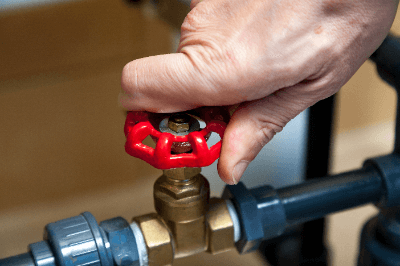
A manual valve (manual operated valve, hand-operated valve) is a valve that opens, closes, or adjusts its degree of opening by human operation (manual operation).
Manual valves are generally classified as globe valves, ball valves, gate valves, butterfly valves, or diaphragm valves, depending on their construction. Valves are used to shut off, “flow”, or “stop” fluids by opening or closing a flow path, and to regulate the flow rate.
Uses of Manual Valves
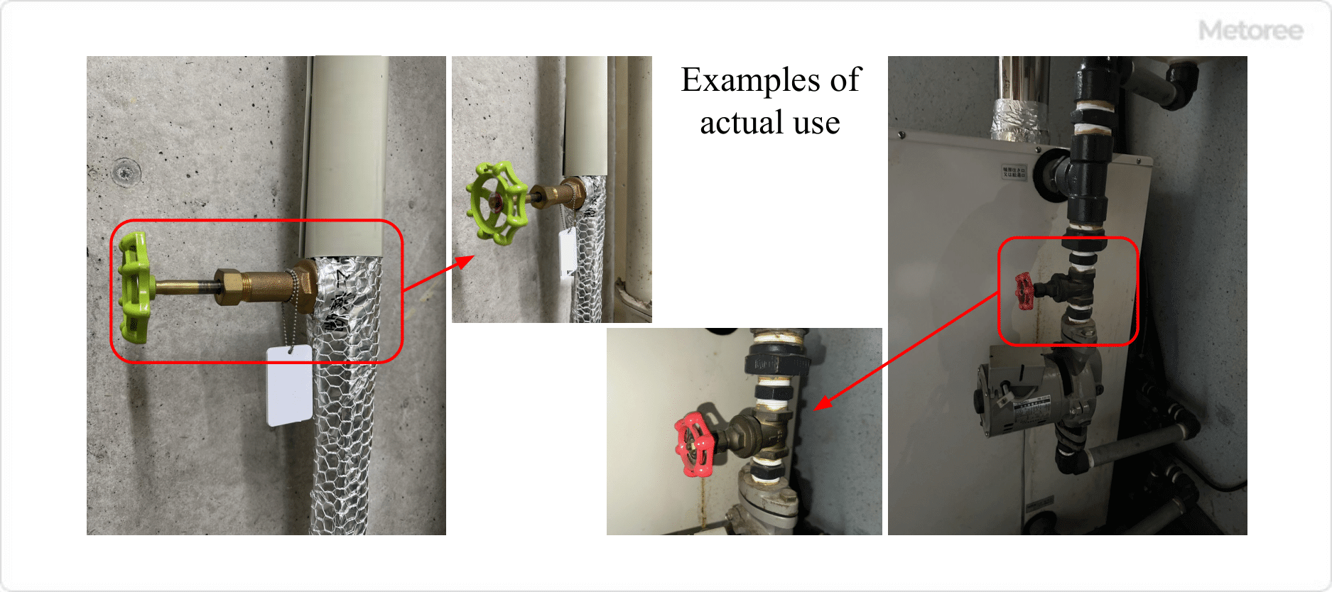
Figure 1. Example of manual valve use
Manual valves are used to shut off fluid or regulate flow and pressure. When shutting off fluid, ball or gate valves are used. Typically, a ball valve is used because it is structurally stronger, leaves no valve plug (ball or disc) in the flow path, and can be opened and closed easily.
Neither of these valves can be used in the mid-open position. Care must be taken because cavitation will occur if the valve is used with the valve plug not fully opened at the halfway position.
Cavitation is a phenomenon in which a liquid becomes low pressure and vaporizes, generating bubbles. Cavitation causes increased vibration, noise, and flow pulsation, and may result in damage to piping and equipment.
Globe valves or butterfly valves are used to adjust flow and pressure. Globe valves are generally used because they are easy to adjust flow and pressure by operating the handle. However, globe valves have an intricate flow path inside the valve box (body), resulting in a large fluid pressure loss.
Principle of Manual Valves
A manual valve has a valve plug (ball, disk, etc.) inside the valve housing (body), and by turning the valve plug up and down, the plug adheres to the seat in the valve housing to shut off the flow path. Manual valves are manually operated to raise, lower, and rotate the valve plug.
The pressure drop across the valve as the fluid passes through the valve varies depending on the valve construction. Pressure drop is an important factor in valve selection. The pressure loss is calculated using the following Fanning’s equation:
ΔP=4f (ρμ2L/2d)
ΔP: pressure loss (Pa), f: friction coefficient, ρ: density of fluid (kg/m3), μ: average velocity of fluid (m/sec), L: pipe length (m), d: inner diameter of inner pipe (m)
Types of Manual Valves
There are several types of manual valves, depending on their construction and function. When selecting a manual valve, it is important to consider the type of fluid used (water, steam, air, gas, chemical, etc.), the pressure and temperature of the fluid, whether it is corrosive or not, and the purpose of use (shut-off, flow, pressure control, etc.).
1. Globe Valve
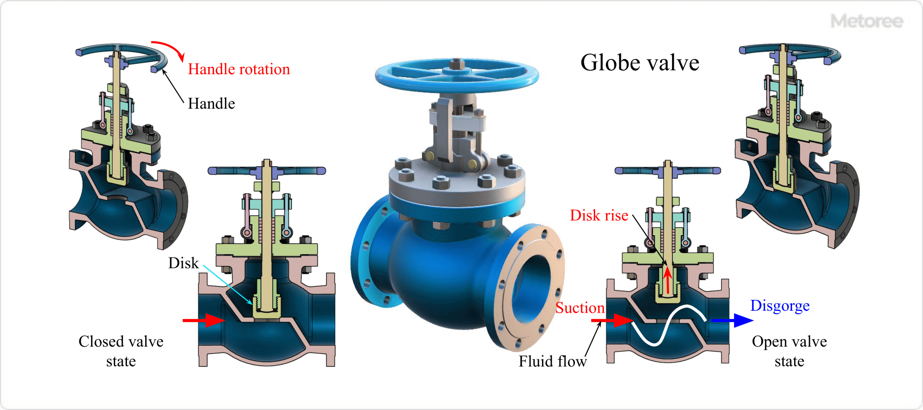
Figure 2. Globe valve
Globe valves are also called globe valves. They are used as stop valves or throttle valves because of their superior ability to shut off fluids and regulate flow and pressure.
The valve box (body) is rounded and the internal flow path is curved. The valve plug (disk) inside the valve box moves up and down by rotating a handle attached to the valve stem.
This causes the valve plug to contact the seat, shutting off the fluid. The distance between the plug and the seat varies with the degree to which the handle is rotated, allowing for flow and pressure adjustment. Used as valves to adjust the volume of utilities such as steam, cooling water, hot water, compressed air, and vacuum lines that require flow and pressure adjustment.
2. Ball Valve
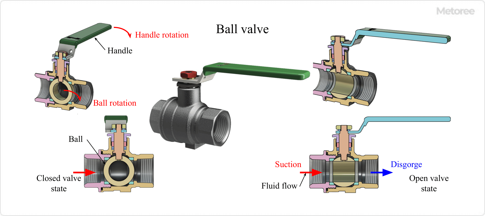
Figure 3. Ball valve
Ball valves are characterized by the spherical (ball-shaped) plug (disc) inside the valve housing (body). The valve plug is rotated by turning the handle attached to the valve stem 90 degrees to shut off the flow path. Ball valves have a small pressure drop because the valve plug does not remain in the flow path when the valve is open.
Basically, they are not used in mid-opening and are not used for flow or pressure adjustment. They are relatively compact and inexpensive, and are often used as small stop valves because they can be closed simply by turning the handle 90 degrees.
3. Gate Valve
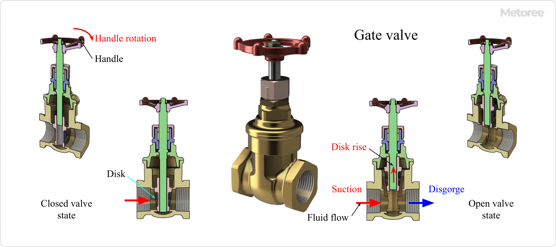
Figure 4. Gate valve
Gate valves are valves used specifically to shut off fluids. The valve plug (disc) inside the valve box (body) moves up and down by rotating a handle attached to the valve stem (stem).
This causes the valve plug to contact the seat and shut off the fluid. The flow path in the valve housing is straight, resulting in a small pressure drop. Used as a stop valve because it is not used in the middle opening position, but in the open-and-closed positions.
4. Butterfly Valve
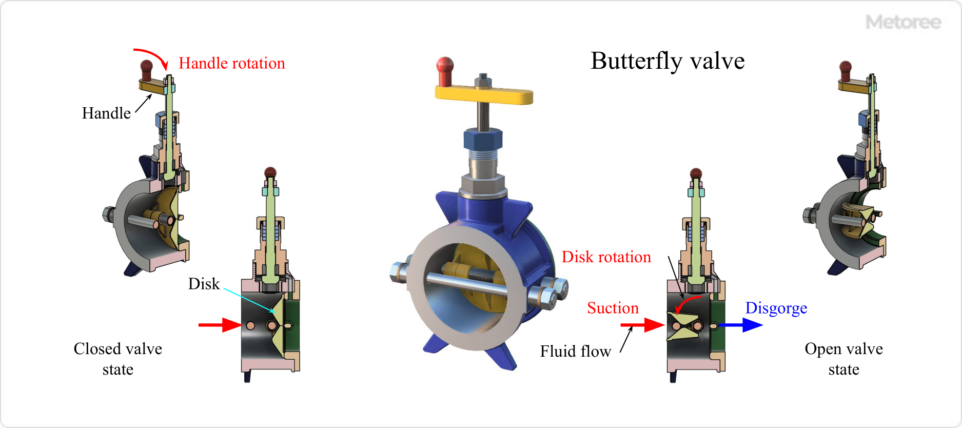
Figure 5. Butterfly valve
Butterfly valves are characterized by the disk-shaped valve plug (disk) inside the valve housing (body). The disc is rotated by turning a handle attached to the valve stem to shut off the flow path.
There are also semi-circular valves with a valve plug that rotates like the wings of a butterfly. Butterfly valves can adjust the flow rate and pressure by adjusting the angle of rotation of the valve plug.
5. Diaphragm Valve
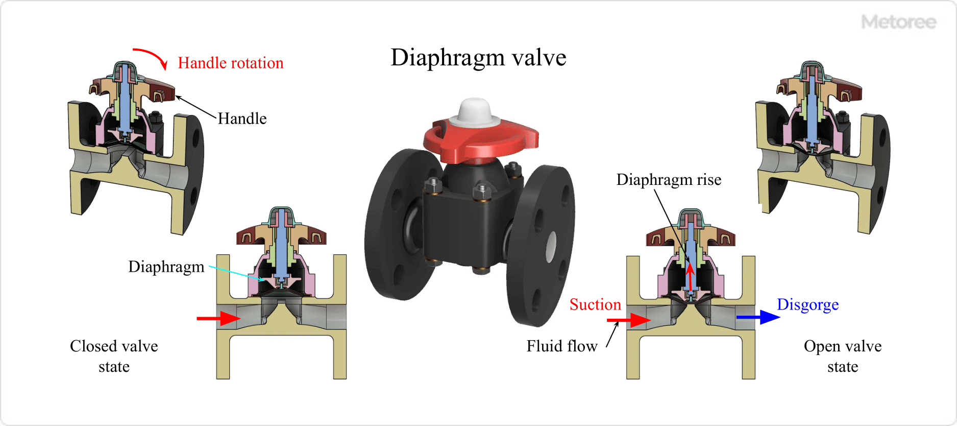
Figure 6. Diaphragm valve
Diaphragm valves shut off the flow path with a diaphragm made of rubber or fluoroplastic. The valve plug (diaphragm) inside the valve box (body) is rotated by a handle attached to the valve stem (stem), causing the diaphragm to deform up and down. This causes the diaphragm to contact the seat and shut off the fluid.
Compared to other valves, the structure is simpler, and the flow path and driving portion are isolated by the diaphragm, making it excellent for highly corrosive fluids. For this reason, it is often used in fields such as medicine, food, and medical care. They cannot be used with high-pressure fluids and are mainly used at low pressures of 0.5 MPa or less.
How to Select a Manual Valve
Select a suitable valve considering the purpose, pressure drop, cost, and other factors. Manual valves do not require electrical wiring or pneumatic piping for the drive unit and can be operated at a lower cost.
Manual valves are contrasted with automatic valves, which are opened, closed, or adjusted by a drive unit (actuator), either remotely or by regulation. The drive (actuator) can be either pneumatically or electrically driven.
In the case of compressed air drive, there are two types: a single acting type in which only the opening action is pneumatically driven and the closing action is performed by a spring, etc., and a double acting type in which both the opening and closing actions are pneumatically driven. In the case of electric drive, screw jacks with electric motors or electromagnetic coils are used for opening and closing.
Other Information on Manual Valves
Manual Valve Symbols
When manual valves are used, they are often in very large installations or extensive areas. As a result, drawings and other information can be very complex.
Usually, the drawings do not show the complete shape of the manual valve, but rather the symbol for the manual valve.