カテゴリー
category_usa

Set Screw

What Is a Set Screw?

A set screw is a type of fastener used to secure an object within or against another object, typically without the use of a nut. Unlike standard screws, set screws are fully threaded and designed to be inserted into a pre-threaded hole to adjust or secure different components.

Set screws are commonly recognized for their lack of a head, allowing them to sit flush with the surface of the object they secure. They can be tightened and loosened using various tools, such as hex wrenches for models with hexagonal sockets or flathead screwdrivers for slotted versions.

The hexagon socket set screw is also known by names like “potato screw” or “enamel set”.

Applications of Set Screws

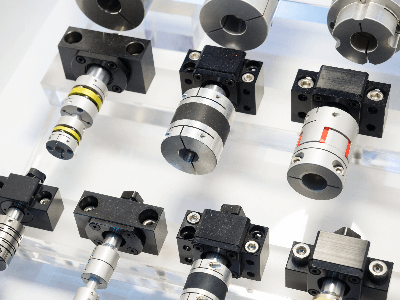
Set screws are widely used in mechanical applications to fix gears, pulleys, and other components onto shafts. They are particularly valuable in situations requiring precise adjustment or securement without significant force, such as positioning a pulley on a motor’s output shaft. However, their use necessitates caution in high-precision assemblies due to potential misalignment caused by the screw’s pressure.

Beyond fixation, set screws also serve in adjusting the force applied by components like compression springs, allowing for fine-tuning of mechanical actions.

Features of Set Screws

Set screws offer a compact, non-protruding solution for component fixation, saving space and reducing cost. They come in various tip designs for different applications, including:

1. Cup Point

The most common type, featuring a concave tip that grips the mating material securely.

2. Flat Point

These have a flat end, minimizing damage to the target material, and are suitable for repeated use.

3. Cone Point

Cone-point set screws have a sharp end that offers excellent resistance against rotation.

4. Dog Point

With a cylindrical end, dog point set screws are ideal for permanent location and alignment within predefined holes.

Types of Set Screws

Set screws vary by drive type, including:

1. Hexagon Socket Set Screw

Featuring a hexagonal indent, these are tightened with a hex key and are versatile for deep holes and secure fastening.

2. Slotted Set Screw

These have a single slot and are adjusted with a flathead screwdriver, suitable for precise, low-torque applications.

3. Square Head Set Screw

With a square external head, these are typically adjusted with a wrench and can be used for both securing and adjusting components.

How to Choose a Set Screw

Material choice for set screws includes steel, stainless steel, and nonferrous metals, selected based on compatibility with the components being secured. Special attention should be paid to material combinations to prevent corrosion or damage, particularly when metal meets resin. Using a locking agent can help prevent loosening in vibration-prone environments.

カテゴリー
category_usa

Gear

What Is a Gear?

Gears are mechanical components that transmit power through toothed profiles. They enable power transmission horizontally or vertically, depending on the tooth configuration. Unlike V-belts, gears prevent slippage, making them crucial for applications where precise timing is essential. By varying gear sizes and tooth counts, it’s possible to adjust rotational speeds, enabling a small motor to drive a large machine efficiently.

Applications of Gears

Gears are ubiquitous in daily life, particularly in power-driven equipment. Common examples include vehicles like cars, motorcycles, and bicycles, as well as household appliances such as clocks, fans, and vacuum cleaners. They are also integral to industrial machinery, including turbines in power plants, blowers, and wind generators. In bicycles, for instance, the gear system, known as a sprocket, allows for speed adjustment by changing gears, directly influencing pedal rotation and movement.

Characteristics of Gears

Gears ensure reliable power transmission without slippage, allowing for precise timing adjustments. However, gear teeth can wear out over time, increasing the gap known as backlash. This can lead to noise or malfunction, especially under fluctuating loads or frequent starts and stops, necessitating regular maintenance. Gears enable acceleration and deceleration adjustments through tooth number and size variations, commonly seen in reduction gears. This ability allows a small motor to operate large machinery, reducing costs related to the motor, energy consumption, maintenance, and equipment size. Proper lubrication with oil or grease is required to minimize wear and extend gear life, with the lubrication method chosen based on equipment specifications and installation location.

Types of Gears

Gears come in various shapes, allowing for parallel, intersecting, or staggered shaft arrangements when paired.

1. Spur Gear

Featuring teeth parallel to the rotation axis, spur gears are widely used for their manufacturing simplicity and effectiveness in power transmission.

2. Internal Gear

A spur gear variant with internal teeth, designed to mesh with smaller diameter gears.

3. Helical Gear

Created by angling the teeth of a spur gear into a helical formation, providing smoother operation.

4. Screw Gear

Paired with a helical gear, it transmits power between two non-parallel axes.

5. Yamaba Gear

Consists of two helical gears with opposite helix angles, counteracting axial thrust.

6. Bevel Gear

Conically shaped with teeth on the conical surface, used for transmitting power between intersecting axes.

7. Crown Gear

A bevel gear variant with teeth perpendicular to the rotation axis, resembling a crown.

8. Worm Gear

Combines a worm and worm wheel at right angles for compact, high-ratio gear reduction.

9. Spherical Gear

Features teeth on a spherical surface, allowing for perpendicular axis operation.

10. Sprocket

Engages with a roller chain to transmit rotation, differing from typical gear mechanisms as it does not involve meshing gears.

Gear Structure

Gear teeth are defined by mathematically calculated curves known as tooth profile curves, categorized into involute, cycloid, and trochoid profiles.

1. Involute Tooth Profile

Defined by an involute curve, this profile ensures consistent meshing even with slight center distance variations, favored for its manufacturability and efficiency.

2. Cycloid Tooth Profile

Characterized by minimal tooth interference and uniform sliding, cycloid profiles are challenging to manufacture but are utilized in precision mechanisms like clocks.

3. Trochoid Tooth Profile

Based on a trochoidal curve, this profile is applied in internal gear pumps for its efficiency and reliability.

カテゴリー
category_usa

Gear-Cutting Machinery

What Is Gear-Cutting Machinery?

Gear-cutting machinery refers to machine tools that create grooves in gears through cutting processes. These machines are essential in the manufacture of both rolled and cast gears, offering precise machining for a wide range of gear types.

The types of gear-cutting machinery include hobbing machines, which process external gears using hob cutters; shaping machines, capable of processing both external and internal gears with pinion cutters; and broaching machines, used for manufacturing with broach cutters. Additionally, there are specialized machines for rack gears, worm wheel hobbing, straight bevel gears, and spiral bevel gear cutting.

Applications of Gear-Cutting Machinery

Gear-cutting machinery is utilized in the production of spur gears, helical gears, internal gears, and racks, which are critical for transmitting power between parallel shafts. These machines also facilitate the creation of straight bevel gears, spiral bevel gears, and face gears for cross-shaft applications, where power transmission shafts intersect. Moreover, they are employed in making worm gears, hypoid gears, screw gears (known as staggered shafts), and specialized gears like noncircular gears, conical gears, and intermittent gears.

Features of Gear-Cutting Machinery

Gear-cutting machinery employs various methods such as the creation method, forming method, and gear skiving, tailored to the specific gear being manufactured. For instance, spur gears are typically processed using the generating method, while special gears may require a combination of generating and forming methods. Primarily used for cylindrical gears, these machines include hobbing machines for hobbing, grinding machines for precision shaping, and gear shapers for special gears, combining creation and forming methods as needed.

Aside from spur gears, hobbing machines also machine helical and worm gears. The generating method is noted for its accuracy over the forming method, which processes grooves individually but at a higher cost, especially when using NC (Numerical Control) machine tools.

Types of Gear-Cutting Machinery

Different gear-cutting machinery types are distinguished by their processing methods:

1. Hobbing Machine

This machine performs gear cutting by rotating a hob cutter in contact with the gear blank, featuring cutting edges and grooves to form the gear.

2. Gear Shaper

Using a pinion cutter or rack-type cutter, a gear shaper executes shaping through vertical blade movement. It’s adept at handling special gear shapes, albeit with lower work efficiency.

3. Gear Grinding Machine

High-speed rotation of the grindstone shapes the gears, allowing for high-precision machining of hardened materials.

4. Gear Shaving Machine

Used in the final stages of gear production, this machine smooths the gear surface and corrects alignment through rotating gear-like tools.

5. Bevel Gear-Cutting Machinery

Specializing in bevel gears, this machinery employs a disc-shaped cutting tool for precision cutting.

Structure of Gear-Cutting Machinery

Gear-cutting machinery is capable of producing gears in various shapes:

1. Spur Gear

The most common gear type, featuring teeth parallel to the gear axis for power transmission between parallel gears.

2. Helical Gear

With diagonal tooth traces, helical gears offer easier meshing, quieter operation, and greater strength than spur gears.

3. Internal Gear

Characterized by teeth that face inward, these gears rotate a smaller gear within a cylindrical space.

4. Bevel Gear

Conical in shape, bevel gears transmit power between intersecting shafts. They are classified into straight (with teeth like those of spur gears) and helical bevel gears (with diagonal teeth).

5. Worm Gear

Consisting of a screw-like worm and a matching worm wheel, worm gears change shaft direction and offer compact, quiet operation compared to bevel gears.

6. Rack and Pinion

A rack pinion system converts rotational motion into linear motion, using a straight rod (rack) with teeth and a gear (pinion), commonly seen in camera tripod height adjustments.

カテゴリー
category_usa

Magnetic Tape

What Is a Magnetic Tape?

Magnetic Tapes

Magnetic tape is a type of storage media that records electronic data by magnetizing a medium attached to the tape.

Capable of storing large volumes of data for extended periods without power, it was widely used in videotapes and cassette tapes.

While originally used for analog data, magnetic tape can also record digital data. Its advantage over hard disks and optical disks, both digital storage media, is the absence of electricity consumption during recording and playback.

Applications of Magnetic Tapes

Magnetic tapes have been used in various applications, including:

1. Cassette Tape

Introduced in the 1960s and popularized by Sony’s Walkman, cassette tapes saw global expansion in sales. Magnetic tapes in cassettes are 3.81 mm wide and coated with a magnetic alloy of pure iron.

2. Data Archives

They serve as data warehouses, safely storing confidential data for long periods and allowing quick retrieval when necessary. Their use reduces costs, as electricity is not needed for storage.

Principle of Magnetic Tapes

The principle behind recording music and storing data on magnetic tapes involves a brown vinyl tape coated with a magnetically active material. Sound recordings are converted from audio signals into electrical signals by a tape recorder, which is then converted into magnetic signals by the recording head, an electromagnet that interacts with the tape’s surface.

Though invisible to the eye, S (South) and N (North) signals are recorded on the tape. During playback, these signals are read by the playback head, amplified, and converted back into sound through the speakers.

Types of Magnetic Tapes

Magnetic tapes are categorized into video tapes and audio cassette tapes, with audio cassettes further divided into normal, high, ferrichrome, and metal position tapes.

1. Videotape

Available in various grades such as normal, professional, hi-fi, and high grade, with recording formats including VHS and S-VHS.

2. Normal Position Tape

Coated with brown ferric oxide for magnetic recording. Optimized for music, these tapes offer excellent maximum output levels (MOL) in the mid-low frequency range.

3. High Position Tape

Coated with chromium oxide or cobalt oxide, known as chrome position tapes. They provide superior signal-to-noise ratio and reproducibility in the mid-high range but are less effective in the mid-low range compared to normal position tapes.

4. Ferrichrome Position Tape

Features a dual-layer coating that combines the strengths of both normal and high-position tapes, offering excellent performance across all ranges. They are compatible with devices that do not specifically support ferrichrome tapes.

5. Metal Position Tape

Uses a vapor-deposited non-oxidized metal magnetic material, allowing for high-density recording with excellent coercive force. Though suitable for use as a master tape, it is not ideal for mass duplication.

How to Choose Magnetic Tapes

Magnetic tapes offer larger storage capacity than semiconductor memory or hard disks, making them suitable for long-term storage due to their reliability, low error rate, cost-effectiveness, and space efficiency.

However, their structure limits random data access, and management becomes more challenging as the number of tapes increases.

カテゴリー
category_usa

Shaft Coupling

What Is a Shaft Coupling?

Shaft Couplings

A shaft coupling, also known as a coupling or joint, is a general term for components that connect two shafts.

Shaft couplings primarily connect the machine side (driven side) to the motor, smoothly transmitting the driving force.

Among various types, flexible shaft couplings are commonly used to absorb vibrations by allowing for shaft misalignment. This flexibility reduces the load on bearings and absorbs shocks and vibrations from the machinery.

Applications of Shaft Couplings

Shaft couplings are widely used in machinery that involves drive and driven transmission mechanisms. For instance, in rotating machines like pumps, blowers, and agitators, shaft couplings connect the motor (drive side) to the impeller shaft (driven side) for power transmission.

1. Flexible Shaft Couplings

These are suitable for machinery prone to misalignment or that generates significant vibrations, with a bush between the flange and bolt to absorb vibrations.

2. Fixed Shaft Couplings

Often utilized in machinery requiring a high transmission capacity.

Principle of Shaft Couplings

Rotational power is transmitted by securing the drive and driven shafts with mounting joints using bolts. Methods of securing the shaft and coupling include key material and set bolts or shrink fitting.

1. Flexible Shaft Couplings

A bush made of rubber or similar material is inserted at each fixing point with a bolt, absorbing shaft runout, vibration, and misalignment while smoothly transmitting power. Regular inspection and replacement are crucial as cracks from aging can reduce flexibility and vibration absorption.

2. Fixed Shaft Couplings

These are bolted into place and require precise centering to prevent misalignment. Without a bushing, they provide lossless power transmission, ideal for situations requiring the transmission of large amounts of power.

Types of Shaft Couplings

Beyond flexible and fixed shaft couplings, there are additional types, such as universal and Oldham shaft couplings. Selection should match the equipment’s specifications.

1. Flexible Shaft Couplings

Commonly used structures include muff and flange types. Muff couplings cover the shafts’ outer periphery with a cylindrical boss, while flange types are connected by inserting flanges into both shaft ends and securing them with reamer bolts.

2. Fixed Shaft Couplings

Varieties include flange type, laminated leaf spring, chain, gear type, and rubber shaft couplings, each serving different requirements.

3. Universal Couplings

Appropriate when connecting axes have significant misalignment or intersect, available in constant and non-constant velocity types.

4. Oldham Shaft Couplings

Suitable for parallel axes with minor misalignment between them.

Structure of Shaft Couplings

With a multitude of types, including rigid, metal slit, metal coil spring, magnet, pin/bush, disc, high damping performance laminated rubber, jaw, and resin bellows types, selection depends on the application and characteristics.

How to Choose a Shaft Coupling

1. Flange Type Flexible Shaft Couplings

A commonly used structure where a rubber bush on one bolt end connects the flanges on both shaft ends, transmitting torque through compressive strength. Its flexibility accommodates shaft center deviations.

2. Laminated Leaf Spring Shaft Couplings

Connects joint flanges with a laminated leaf spring to transmit torque, accommodating misalignment and angular misalignment thanks to its flexibility.

3. Chain Shaft Couplings

Two hubs on the axes to be connected are fitted with sprockets of the same tooth count and connected by a chain, offering limited flexibility.

4. Gear Type Shaft Couplings

Internal teeth on the inner cylinder mesh with external teeth on the boss part’s external cylinder, transmitting large torque.

5. Rubber Shaft Couplings

Entirely made of rubber, compared to flange-type flexible shaft couplings, these accommodate misalignments in all directions thanks to the rubber elastic body.

カテゴリー
category_usa

Mounted Point

What Is a Mounted Point?

A mounted point is a type of grinding tool with a spindle, primarily used in metalworking for grinding, polishing, chamfering, and rust removal. It comes in various materials and hardnesses, typically featuring abrasives like alumina, silicon carbide, and ceramics.

Applications of Mounted Points

Mounted points are essential for precision polishing in automotive, electronics, and mechanical parts production. They excel in localized or deep polishing tasks that are challenging with standard polishing equipment, also aiding in rust and debris removal.

Features of Mounted Points

Advantages

These tools offer precise alignment between the grinding surface and spindle, ensuring high-precision grinding and stability. Their direct attachment to the spindle enhances durability and efficiency, allowing for rapid and accurate grinding without excessive wear.

Disadvantages

Their use is limited by the spindle size, and large diameters can cause abrasive grains to detach if spun too quickly, necessitating lower speeds. Installation can be time-consuming, and improper setup may pose safety risks.

Using Mounted Points

The process involves selecting the appropriate grindstone, adjusting the grinding position, setting the rotation, performing the grind, and applying coolants or lubricants to manage heat and remove debris.

Types of Mounted Points

Mounted points are categorized by shape, abrasive material, and binder type. Alumina is used for hard materials, silicon carbide for steel and stainless steel, and other materials like boron nitride and diamond offer high hardness for specialized applications.

Other Information

Bonding Agents for Mounted Points

The performance and application of mounted points vary with the bonding agent—metal, ceramic, or resin—each offering different levels of bonding strength, heat resistance, and suitability for polishing or high-speed machining.

カテゴリー
category_usa

Axial Flow Fan

What Is an Axial Flow Fan?

Axial Flow Fans

An axial flow fan is a type of fan that cools equipment. Air flows in from the front of the rotating blades (propeller) and out the back. Since the air flow is along the axis of rotation, it is called an axial flow fan. There are various types of fans, but the flow of air along the axis of rotation distinguishes axial fans from other fans.

Axial flow fan is available in both AC and DC power supply types, but a DC-powered axial flow fan can be easily controlled with a PWM signal when it is necessary to control the rotation speed.

Uses of Axial Flow Fans

Axial flow fans are used for cooling equipment. Specifically, they are used to cool the motors, driver circuits (circuit boards), microcontrollers, and other components installed in equipment to prevent malfunctions and damage due to heat.

They are used for purposes other than cooling in equipment that primarily handles paper, such as copiers and printers. By blowing air on a bundle of paper. Paper is removed one sheet at a time, or paper is sucked and transported by using the air-sucking power of a fan. It is also used for drying ink after printing.

Axial flow fans are also used in enclosed spaces to stir the air and exhaust air to prevent uneven temperature and humidity inside.

Principle of Axial Flow Fans

Axial flow fans have blades (propellers) placed in the center of the enclosure, and by rotating the blades, air is expelled from the front of the blades to the rear. Axial flow fans are low-noise and provide high airflow, but there are also a wide variety of products with enhanced features such as high airflow, high static pressure, and low noise.

Two axial flow fans can be connected in series or in parallel. When operating them in series, the airflow rate remains the same, but the static pressure can be increased. When they are operated in parallel, the static pressure remains the same, but the air volume can be increased.

When used for cooling, it is necessary to decide whether to use the airflow for discharge or suction, depending on the number and location of components that generate heat in the equipment. Dust in the air should also be considered. When used in a normal environment, dust in the air is also circulated during cooling, so dust will accumulate on the board over time, especially if the air is blowing directly onto the board. When this happens, consider installing a filter if necessary.

カテゴリー
category_usa

Dust Collector

What Is a Dust Collector?

Dust Collectors

A dust collector is a device used to collect dust and other particles.

It is used as a device to treat exhaust gas and dust. A household vacuum cleaner can also be classified as a dust collector if it is considered as a device to treat dust on the floor.

Uses of Dust Collectors

Dust collectors are used for both industrial and residential purposes. However, they differ in size and construction.
Specific applications are as follows:

  • Exhaust gas equipment for boilers used in power generation
  • Exhaust gas equipment for iron and steel plants and smelting plants
  • Air cleaners and air conditioners with dust collectors
  • Air cleaners for clean rooms
  • Sawdust collection for woodworking workshops 
  • For cleaning dirty rooms

Principle of Dust Collectors

The majority of dust collectors on the market are centrifugal dust collectors. Centrifugal dust collectors rotate gas at high speed inside a cylindrical structure and collect dust to the sides by centrifugal force. They are easy to maintain and suitable for collecting relatively large dust particles.

Most household vacuum cleaners are based on the same principle as centrifugal dust collectors. Centrifugal dust collectors have the advantage of being compact and lightweight because of their simple structure and small number of parts.

Types of Dust Collectors

In addition to the centrifugal dust collectors described in the principle section, various other types of dust collectors are used in industrial applications. The following four types of dust collectors are typical. 

1. Centrifugal Dust Collector (Cyclone)

As mentioned above, the principle is that centrifugal force is used to collect dust. However, the collection limit is about 10 μm, and it is not suitable for collecting particulates smaller than 10 μm. The equipment must be rotated, which causes mechanical strength problems and eccentricity, making it unsuitable for larger sizes.

2. Washing Type Dust Collector (Wet Scrubber)

A typical example of a cleaning dust collector is a scrubber. This device sprays a circulating liquid into exhaust gas and collects dust particles in the exhaust gas by the moisture of the circulating liquid. By controlling the PH of the circulating liquid, the chemical properties of the exhaust gas can be stabilized. However, it is necessary to use an additive device or additive agent regularly to keep the PH constant.

Dust collection performance is also high, and dust as small as 0.1 μm can be collected. However, the running cost is more expensive than other dust collectors. 

3. Filtering Dust Collector (Fabric Filter)

The filtration type collects dust by passing exhaust gas through a filter cloth to which the dust adheres, effectively collecting particles as small as 0.1 μm in size and featuring high dust collection efficiency. On the other hand, the dust collection capacity tends to deteriorate due to clogging of the filter cloth, so periodic cleaning and replacement are required, and the running cost is high. 

4. Electrostatic Dust Collector

Electrostatic dust collectors of a collecting plate and a discharging electrode, and collects particles using the Coulomb force acting on charged particles. The fine particles are charged by corona discharge at high voltage. The dust collection performance is capable of collecting more than 99% of submicron-level dust particles of about 0.05 μm.

In addition, because they are easy to maintain and have low running costs, electrostatic precipitator dust collectors have become the mainstream dust collectors for power generation plants in recent years. Electrostatic precipitator dust collectors are sometimes called a Cottrell after the developer.

Other Information on Dust Collectors

1. Dust Collectors and the Clean Air Act

Large dust collectors are used in industrial applications to treat exhaust gases. They are used in power plants, steel mills, and other plants with boilers and furnaces. Boilers and other equipment may cook with heavy oil or coal as fuel, and the exhaust gas contains a lot of carbon dust. This dust is called soot, and in the past, soot and dust have caused health problems.

Since exhausting soot and dust as it is leads to pollution, the laws stipulate that the soot and dust in exhaust gas be collected. In addition, each state has its own regulations on the amount of dust in factory exhaust gas, and dust collectors are used to meet these emission standards. 

2. Dust Treatment of Dust Collectors

Dust collected by dust collectors is considered industrial waste for industrial use. Therefore, it cannot be disposed of in the open. The dust generated from boilers and other equipment is disposed of in landfills at final disposal sites registered with the government. Chips generated in the woodworking and forestry industries are sometimes used as valuable materials for biomass power generation.

カテゴリー
category_usa

Filling Machinery

What Is Filling Machinery?

Filling Machinery

Filling machinery automates the process of filling containers like bottles, cans, and tubes with products such as liquids or powders. This machinery enhances production capacity, and accuracy, and reduces labor costs.

There are two main types: semi-automatic machines that require operator input to fill a set amount and fully automatic machines that handle the entire process from filling to capping and labeling.

Applications of Filling Machinery

These machines are pivotal in automating production processes across various industries, including food, cosmetics, and daily essentials. They increase production speed, improve work accuracy, and enable precise reproducibility through computer management.

While the most common type fills a predetermined amount into continuously supplied containers, specialized machines exist for products requiring multiple contents, such as cosmetics.

Principle of Filling Machinery

Gravimetric filling, using a load cell for weight measurement, is standard for liquids and powders, ensuring consistent fill volumes and facilitating next steps like capping. Special considerations are made for material adhesion and scattering.

1. Liquid Filling Machinery

These machines may also use level sensors for filling, balancing accuracy with visual fill level alignment.

2. Powder Filling Machinery

Powder fillers often incorporate augers to manage the material flow and measure fill amounts accurately, preventing spillage.

Types of Filling Machinery

Divided into liquid and powder filling machines, each type caters to specific industry needs, from food to chemicals and pharmaceuticals, accommodating various container shapes and materials.

1. Liquid Filling Machinery

These machines vary to handle different volumes and viscosities, from water-like to highly viscous substances, ensuring compatibility with all container types.

2. Powder Filling Machinery

Designed for materials with low fluidity, auger fillers improve material discharge and fluidity, allowing for accurate, high-speed filling.

Choosing Filling Machinery

How to Choose Filling Machinery

There are many types of filling machinery, so you need to consider the advantages and disadvantages when choosing one.

1. Screw-Type Filling Machinery

This is a powder filling machinery that sends out and weighs powder.

2. Vibratory Feeder Filling Machinery

This method transfers the filling by vibrating the solid material.

3. Tube Pump Filling Machinery

This is a liquid filling machinery that sucks up the filling material from a tube, transfers it with a pump, and fills it while measuring it with a weighing machine.

4. Rotary Filling Machinery

This is a machine that can fill viscous materials by placing two rotors in the pump chamber and sending out fluids by changing volume.

5. Piston Type Filling Machinery

This is a filling machinery that sucks in the filling and spits it out like a large syringe.

カテゴリー
category_usa

Calciner

What Is a Calciner?

Calciners

A calciner is a machine that uses high-temperature steam or infrared rays to rapidly bake foodstuffs.

Commonly utilized in the food processing and service industries, including restaurants, calciners support various applications like grilling, defrosting, and baking sweets.

Calciners come in several types, including superheated steam and light heating types. The former uses steam for heating, while the latter employs infrared rays, affecting firing efficiency and quality based on the method and ingredients used.

Uses of Calciners

Calciners are versatile in their applications:

1. Grilling

They can grill a wide range of foods, including fish, meat, and vegetables, directly from frozen states, particularly using the superheated steam type.

2. Thawing

Calciners efficiently thaw frozen foods, notably with the superheated steam method, reducing thawing time.

3. Baking and Heating

They’re used for baking sweets, heating dry goods, and steaming bread.

4. Roasting

Calciners are ideal for roasting coffee, tea, and nuts, ensuring even roasting.

5. Sterilization

In the food processing industry, calciners sterilize products, removing bacteria from food surfaces with superheated steam.

6. Other Applications

They’re also used for desalinating seafood and meat and manufacturing medical disinfection equipment.

Advantages and Disadvantages of Calciners

Advantages

Calciners evenly bake food with superheated steam, preserving nutritional value and enhancing natural flavors without the need for oil, offering healthier cooking options. They perform multifunctional cooking, saving space and time.

Disadvantages

Temperature control in calciners can be challenging, requiring precise timing and constant temperature maintenance. Regular cleaning is necessary to prevent equipment deterioration and clogging from food residue.

Types of Calciners

Calciners vary in their heating methods:

1. Superheated Steam Type

Uses high-temperature steam for baking.

2. Light Heating Type

Employs infrared rays, with methods ranging from near to far infrared heating.

3. Electric Heating Type

Heats food using electricity, suitable for both household and industrial use.

4. Gas Type

Utilizes gas combustion for rapid, high-temperature heating.

5. Microwave Type

Uses microwaves to penetrate food, heating it internally and externally.

Structure and Process of Calciners

A superheated steam calciner operates through steam generation, surface heating, and internal food heating, ensuring efficient and even cooking.

Other Information on Calciners

Calciners also find applications in fermentation, smokeless baking, industrial product manufacturing, and precise control over firing conditions for quality control.