カテゴリー
category_usa

Plastic Valves

What Is a Plastic Valve?

Plastic Valves

A plastic valve is a type of valve made from plastic materials, such as PVC or PTFE.

While some valves made of stainless steel or cast iron may incorporate plastic components, plastic valves are entirely constructed from plastic materials.

Plastic valves are typically employed in corrosive environments where plastic is the only suitable material or in situations where metal valves are not feasible.

However, due to their resin-based construction, plastic valves have lower absolute strength compared to metal valves. Additionally, extended exposure to sunlight may result in deterioration and a loss of strength.

Uses of Plastic Valves

Plastic valves are frequently used in corrosive chemical pipelines, capitalizing on their resistance to chemical degradation. They excel in handling highly concentrated hydrochloric acid, such as 35% hydrochloric acid, and are commonly chosen when strength is not a concern.

For applications involving sulfuric acid, high concentrations may require steel galvanized pipes (SGP), but for hydrochloric acid, resin-based valves become the primary choice.

Plastic valves are also preferred when dealing with corrosive fluids in situations where various liquids are mixed. Valves made from low-elution resin can even be used in pure water pipelines without issues.

Principle of Plastic Valves

Plastic valves are primarily constructed from materials such as PVC or PTFE, imparting them with high corrosion resistance.

One significant advantage of plastic valves, in addition to their corrosion resistance, is their lightweight nature, exerting minimal stress on the piping system.

Valves made from stainless steel with PFA coating or rubber lining can be heavy and labor-intensive to install. If the coating or lining becomes damaged, it can lead to rapid corrosion in those areas.

Plastic valves, on the other hand, are lightweight and inherently corrosion-resistant, offering a significant advantage in this regard.

However, due to the characteristics of plastic materials, they may degrade when exposed to ultraviolet light. Similar to how plastics outdoors often turn white over time, PVC can gradually deteriorate and lose strength. Consequently, when PVC is used outdoors, periodic replacement may be necessary.

Additionally, being plastic, their impact resistance is lower. Therefore, careful consideration is required when using PVC in pipelines susceptible to water hammer, and adequate piping support must be ensured.

カテゴリー
category_usa

Horizontal Milling Machinery

What Is Horizontal Milling Machinery?

A milling machine is a machine in which a blade called a milling cutter is installed on a spindle and rotated to process an object fixed to the machine.

A milling machine with the spindle mounted in a direction transverse to the ground is called a Horizontal Milling Machinery or Horizontal Type Milling Machine. They can be further classified not only by the direction in which the spindle is mounted but also by differences in operation, such as whether the table is moved or the spindle is moved.

While vertical milling machines are generally used in most cases, horizontal milling machinery is suitable for machining grooves, holes, and cutting, and can perform side machining that is not possible with other milling machines.

Cutting tools attached to the spindle can be roughly classified into bores and shanks as defined by JIS standards, and the type of machining that can be performed on a milling machine can be changed by changing the cutting edge.

Uses of Horizontal Milling Machinery

Horizontal milling machinery uses flat milling machines, side milling machines, corner milling machines, etc. Flat milling machines are not often used for plane milling because flat milling is not efficient.

Horizontal milling machinery is often used for milling grooves, steps, and sides. Machining can be varied by changing the shape of the uniform cutting edges on both sides.

Square milling cutters have angled cutting edges on the circumference and can machine v-shaped grooves by cutting in two places at the same time.

The shank type is a rod-shaped tool such as an end mill, and the cutting edge on the tip is used to cut a hole or groove.

Principle of Horizontal Milling Machinery

In a milling machine, the object is fixed to the machine and a blade called a milling cutter is attached to the spindle, which is installed horizontally to the ground, in accordance with the processing.

In machining with a milling machine, the reference is taken to be a surface, and the cutter is brought into slight contact with the object, and the part that has been slightly shaved is set as the zero point, and the entire surface is shaved for machining.

Horizontal milling machinery differs from vertical milling machinery in that it has its spindle facing sideways to the ground to change the direction and transmission of force, and in addition to machining deep holes, which is not possible with vertical milling machinery, only horizontal milling machinery can perform side machining.

Also, with horizontal milling machinery derived from horizontal machining Centers, there are machining centers that can rotate the table 360° under NC control, enabling machining on four sides by rotating the table.

The advantage of the horizontal machining center is that the backside can be machined without removing the workpiece from the table.

Other Information on Horizontal Milling Machinery

1. Characteristics of Horizontal Milling Machinery

Horizontal milling machinery has a feature that chips released during machining do not easily accumulate on the workpiece or fixed jig because the spindle is machined horizontally to the workpiece.

If too many chips accumulate on the workpiece, various disadvantages may occur, such as reduced visibility, scratches on the jig and workpiece, damage to the cutting tool, and the generation of composed cutting edges, which must be cleaned regularly or blown away with a blower.

Horizontal milling machinery is used for applications that require continuous machining for a relatively long period, such as mold carving, taking advantage of its feature that chips do not accumulate easily.

The automatic pallet changing function enables continuous unmanned operation without setup changes.

2. Cautions for Horizontal Milling Machinery

If you are accustomed to handling a vertical milling machine, it is easy to get confused about the X/Y direction.

Also, due to the horizontal nature of the cutting tool mounting, if a heavy cutting tool with a long holder is mounted, it will deflect under gravity, resulting in a loss of accuracy and rigidity. Therefore, it is necessary to chuck knives with a holder length as short as possible compared to vertical milling machines.

It is also necessary to adjust the coolant direction and pressure, paying attention to the fact that gravity makes it difficult for the coolant jet from the spindle to reach the cutting edge, which is a weakness unique to the horizontal type.

カテゴリー
category_usa

Galvanometers

What Is a Galvanometer?

Galvanometers

A galvanometer is a device designed for measuring electric current. In its simplest form, a galvanometer measures current by clamping onto a cable. The output display can be either analog or digital.

Galvanometers come in a wide range of current measurement capabilities, spanning from milliamperes to several amperes. They find applications in various fields, including manufacturing, where they are used to measure very small currents such as microamperes.

Uses of Galvanometers

Galvanometers are essential for detecting electric currents in electrical and electronic components.

Simple galvanometers are commonly used for equipment maintenance and product inspection due to their compact, lightweight, and portable nature. They are employed to measure currents in circuits where a permanent current indicator is not installed. Additionally, they are often utilized in elementary school science experiments due to their ease of use and cost-effectiveness.

In industrial settings, where current is a fundamental physical quantity, galvanometers play a crucial role in product development and quality control, particularly in industries such as semiconductors and functional materials. Specialized galvanometers, known as electrometers, are used for measuring extremely small currents, even in the nanoampere range, especially in information equipment.

Principle of Galvanometers

A typical galvanometer comprises a movable coil, a permanent magnet, a pointer, and a coiled spring.

The movable coil is situated within a permanent magnet, which generates a magnetic field. The pointer moves in coordination with the movable coil. When an electric current flows through the coil, the pointer’s position corresponds to the current’s magnitude, providing a current reading. When the current ceases, the coiled spring returns the pointer to the zero position.

Other Information on Galvanometers

1. Precautions When Using Galvanometers

Galvanometers have current limits, and exceeding these limits can lead to damage or disconnection of the movable coil. The allowable current value is specific to each galvanometer and should be checked before measurements. Excessive current can also generate Joule heat, potentially causing coil damage. For precise measurements of tiny currents, consider using devices like electrometers to ensure accuracy.

2. Difference Between Galvanometer and Ammeter

Both galvanometers and ammeters are instruments for measuring current, but galvanometers are a type of ammeter. Galvanometers are used for detecting minute current values and determining current direction. Ammeters, on the other hand, quantitatively measure current values and are typically employed for measuring larger currents. Unlike galvanometers, ammeters do not provide information about the current direction.

3. Prohibited Use of Galvanometers

It is strictly prohibited to connect a power supply directly to a galvanometer. Galvanometers have very low internal resistance, and a direct connection to a power supply can damage the movable coil. Therefore, when connecting a galvanometer to a power source, always use it in conjunction with an electrical resistance.

4. Symbol of Galvanometer

In electrical circuit diagrams, ammeters are represented by the symbol “A,” voltmeters by “V,” and galvanometers by “G.” Galvanometers are denoted by the letter “G” in honor of the Italian physicist Luigi Galvani, from whom the name “galvanometer” is derived.

カテゴリー
category_usa

Underground Pipes

What Is an Underground Pipe?

Underground pipes are channels used to manage water, primarily in agricultural settings. Culvert drainage involves burying pipes underground to redirect water away from the groundwater table and the surface. This offers benefits such as improved soil drainage and enhanced efficiency of agricultural machinery. Since these pipes are buried, it’s essential to use materials that are durable, easy to install, and environmentally friendly. The choice of construction method should also suit the specific crop and region. For instance, in cold climates, pipes suitable for freezing conditions are preferred to mitigate the risk of freezing.

Uses of Underground Pipes

Underground pipes are predominantly installed in agricultural areas like fields and orchards. They provide several advantages to agriculture, including lowering the groundwater table and controlling drainage. Firstly, they positively impact crops by creating a better growth environment, preventing issues like root rot. Secondly, they enhance farmland usability by aiding in snowmelt during early spring and improving soil temperature. This facilitates soil management, access to agricultural machinery, and the overall versatility of the farmland. Additionally, culvert drainage pipes may also be installed in residential yards to enhance drainage.

Principle of Underground Pipes

Culvert drainage can be broadly categorized into two types: surface water drainage and seepage water drainage. The primary material used for underground pipes is polyethylene. However, other materials are also utilized for specific underground applications and convenience:

  • Rigid PVC Pipe: Lightweight and easy to handle, suitable for various soil types. However, they are vulnerable to low temperatures and impacts and are not suitable for soft ground.
  • Polyethylene Pipe: Suitable for a wide range of soil types and resistant to low temperatures, though they have lower strength.
  • Vinyl Chloride Corrugated Pipe: Rigid with burial method options but sensitive to low temperatures and impacts.
  • Polyethylene Net Pipe: Offers a large water-absorbing cross-section and low-temperature resistance, but is less adaptable to soil properties.
  • Concrete Pipe: High pressure resistance, but heavy and challenging to install.
  • Ceramic Pipes: Applicable for many soil types but challenging to handle and install due to their weight.
  • Polyethylene Corrugated Pipe: Provides higher strength against pressure and low-temperature resistance compared to standard polyethylene but with slightly higher roughness and reduced water flow.

Underground pipes are buried alongside a hydrophobic material, collectively known as the main culvert. Hydrophobic material selection considers factors such as permeability, availability, durability, and its impact on water and soil contamination. Safe materials like rice husks, gravel, and bamboo are used. Based on the main culvert, auxiliary culverts like soil crushing, trenching, perforated culverts, and bullet culverts are employed to further enhance drainage.

カテゴリー
category_usa

Slewing Bearings

What Is a Slewing Bearing?

Slewing bearings are bearings used in the operating parts of construction and civil engineering machinery, especially those parts that operate in a slewing motion.

They are widely used because they have the standard form of a single-row ball bearing and are relatively easy to handle. Slewing bearings have a structure that can simultaneously support single loads and composite loads with respect to moments and other loads.

The moment is the sum of the loads applied to the bearing vertically by the thrust, horizontally by the radial, and the distance between the center of the bearing axis and each point of action of the thrust and radial loads, which are added up to the respective loads.

Slewing bearings are characterized by their high load-carrying capacity. Slewing bearings allow for lower friction in the slewing motion, thus extending the service life of the bearing in practical use.

Applications of Slewing Bearings

Slewing bearings are widely used as bearings in the slewing sections of large machines because they can support combined loads and sustain large loads.

Specific examples of applications are as follows

1. Construction and Civil Engineering Machinery

  • Hydraulic excavators
  • Attachments
  • Cranes
  • Earth augers
  • Small excavators
  • Aerial work vehicle
  • Table Lifter
  • Special vehicles

2. Equipment Machinery

  • Wind power generator
  • Parking lot turntable
  • Inspection table for automobiles, etc.
  • MARUHAN equipment
  • Weighing equipment
  • Food-related rotating equipment
  • Iron and steel-related equipment
  • Sludge scraping machine
  • Wire drawing winder
  • Winches
  • Amusement equipment
  • Rotating drum for garbage storage
  • Revolving stage equipment

3. Precision Machinery

  • Industrial robots for equipment
  • Polishing machines for semiconductor manufacturing
  • Liquid crystal-related polishing machine
  • Injection molding machine
  • Indexing tables
  • Medical equipment
  • Radar

Principle of Slewing Bearings

The internal structure of a skewing bearing is the same as that of a standard ball bearing. There is an arc of the inner and outer ring raceways, and the balls are uniformly arranged in a single row inside the arc.

This makes it possible to use even large ball diameters and to design a bearing that is structurally compact but can carry a large load. By machining and mounting gears directly on the inner or outer rings, driven slewing is possible, and the slewing section can be simplified and made lighter.

However, the size of the thrust load that can be supported depends on the size of the balls that are the rolling elements of the bearing. The size of the balls must be determined by calculating the diameter of the balls that is sufficient for the size of the load that needs to be applied.

Other Information on Slewing Bearings

1. Application of Slewing Bearings to Construction Machinery

Slewing bearings are widely used in construction machinery. Slewing bearings enable smooth slewing operation of heavy structures such as power shovels and cranes. The same is true for small cranes used in residential areas.

Slewing bearings are fastened between the upper slewing body and the lower structure with a large number of bolts. As for maintenance, regular greasing of the slewing bearing is necessary. If the grease is depleted, the slewing bearing area will generate abnormal noise and the sliding during slewing will be faulty, making it impossible to perform fine operations.

Resistance during slewing can cause twisting of the entire machine, so regular greasing is essential. As maintenance other than greasing, inspect the slewing bearing fastening bolts on construction machinery for loosening or elongation of the fastening bolts, as these bolts are subjected to large forces during operation.

Continued use of a slewing bearing with loose or stretched fastening bolts could, in the worst case, result in rupture of the fastening bolts or rupture of the slewing bearing, causing a serious accident. To prevent this from happening, it is important to inspect the bolts periodically.

2. Repair of Slewing Bearings

Repairing slewing bearings is a time-consuming and expensive process, depending on the size and the area of use. If the machine is a heavy construction machine, the slewing bearing is located between the upper slewing body and the lower structure, so the upper slewing body must be removed using an overhead crane.

This process is time-consuming and requires workers who are skilled and knowledgeable about the product. Slewing bearings can be prevented from failure through proper product handling and maintenance.

カテゴリー
category_usa

Disconnects

What Is a Disconnect?

Disconnects

A disconnect is a device used to open or close a circuit that is not carrying load current.

Also called a disconnector, it can disconnect a load circuit from the power supply. However, a disconnect cannot be opened on a circuit with a load current flowing. If a load current is opened with a disconnect, there is a high possibility that it will lead to an explosion or fire due to arcing. Therefore, they are used with circuit breakers that can interrupt the load current.

Uses of Disconnects

Disconnects are used only in industrial applications because they are dedicated high-voltage or special high-voltage electrical equipment.

Disconnects are used when checking or repairing high-voltage equipment to prevent electric shock when touched by a person. The purpose of using a disconnect is to disconnect an electrical circuit from the power source.

Principle of Disconnects

A disconnect consists of a blade, a catch, a base, and a supporting insulator.

1. Blade and Catch

The blade and catch are conductive points. When the blade fits into the catch, it conducts, and when it moves away, it opens. It is mainly composed of hot-dip galvanized with copper or other materials. The blade is provided with a hook fitting to hook an operating rod called a gis conductor rod.

2. Base

The base is the point where it is fixed to the enclosure. The base is made of steel or other material and secures the switchgear to the substrate for the high-voltage switchgear.

3. Support Insulator

Supporting insulators insulate the base and conductive parts. It is made of insulating resin or porcelain.

Types of Disconnects

There are two types of disconnects: V-type disconnects and 3-pole interlocking single-throw disconnects. They are classified by operating voltage into those for special high-voltage and those for high-voltage.

1. V-Type Disconnect

This is a disconnect that disconnects only one phase individually. It is called a V-type disconnect because the supporting insulators support the catch from two directions, giving it a V-shaped appearance. They are compact and economical.

2. 3-Pole Interlocking Single Throw Disconnect

Three-phase disconnects are interlocked, enabling the disconnection of three phases in a single operation. While easy to operate, the disconnector is large due to the structure of the operating mechanism. Disconnects with an automatic locking function, described below, are usually 3-pole interlocking single-throw type.

There is no significant difference in the configuration of disconnects for special high-voltage and high-voltage applications. However, the components for special high-voltage disconnectors are larger due to the need for longer insulation distance and greater robustness.

Other Information on Disconnects

Precautions for Operating Disconnects

Disconnects for high-voltage use are opened and closed mainly by hand. It is operated with an insulating plastic rod called a disconnecting rod. The disconnecting rod is inserted into the hook fitting of the blade to open and close the disconnector. Since the rod is in direct contact with the charging section, it must have excellent insulation and waterproofing properties.

Disconnects do not have an arc-quenching function like circuit breakers. If the load current is released by a disconnect, an explosion will occur due to arching. As a result, the power company’s transmission line could black out, leading to damage. Furthermore, there is a risk of personal injury.

Therefore, the greatest caution in disconnects is the erroneous load current interruption. Measures must be taken to prevent this. Generally, accidents are preventable by preparing written procedures. To ensure that the order of circuit breaker operation is correct, the procedure manual must be checked by several people.

Equipment with an automatic locking function may be used. This mechanism locks the disconnect so that it cannot be operated unless the load current is interrupted by the circuit breaker.

カテゴリー
category_usa

Rectifiers

What Is a Rectifier?

Rectifiers

A rectifier is a device that rectifies current using semiconductor elements.

Rectification is the conversion of alternating current to direct current and is produced by utilizing the property of diodes, etc., to conduct current in only one direction.

Uses of Rectifiers

Rectifiers are widely used to supply DC power.

Familiar examples are AC adapters for supplying power to PCs and smartphones. In industrial applications, they are used for large motor control and electrolysis. Rectifiers, such as thyristors, have long been used for motor control.

Trains are typical machines powered by DC motors and have been fed with rectifiers. In recent years, speed control of AC motors has become common, and trains powered by AC motors have become widespread on train lines. Inverters that control the speed of AC motors use semiconductors called bipolar transistors or IGBTs.

Principle of Rectifiers

Rectifiers use semiconductors to convert AC power into DC power. There are various types of semiconductors, including diodes that conduct current in only one direction and thyristors that conduct current only when a signal arrives at the gate.

All of these semiconductors are made by a pn junction combining p-type and n-type semiconductors and utilize the energy level difference between the semiconductors.

Other Information on Rectifiers

1. Semiconductors Used in Rectifiers

Diodes are composed of p-type and n-type semiconductors. p-type semiconductors have a higher energy level than n-type semiconductors. Therefore, p-type holes can easily flow to n-type semiconductors, while n-type electrons have difficulty flowing to p-type semiconductors. As a result, the current flows when the p-side potential is high, while the current does not flow when the n-side potential is high.

The p-side terminal is anode and the n-side terminal is a cathode. A thyristor is composed of semiconductors stacked in the order of p, n, p, n, with the gate terminal taken out from the middle p part. By applying voltage from this gate part to the cathode side, the current can flow from the anode to the cathode.

This is called turn-on. If you want to turn off a thyristor that has been turned on, you can return it to its original state by making the voltage on the cathode side higher than the anode side.

2. Rectifier’s Role in Industry and the Home

Rectifiers have long been used in factories and homes. The electricity used for home landline telephones is DC voltage converted to DC by a rectifier. Rectifiers are also built into AC adapters used to charge computers and smartphones. Rectifiers are always used inside the electronic circuits of inverter air conditioners, which use inverters to control the temperature.

Rectifiers are also widely used in the industry up to the present day. Many DC feeder lines with rectifiers are still in use in trains. Rectifiers are used for electrolytic refining in aluminum plating plants. Some arc furnaces, for example, use DC current, and rectifiers are used as power sources.

Demand for rectifiers is expected to increase in the future. Electric vehicles are loaded with numerous batteries to withstand long-distance driving. Batteries cannot be charged using AC power and must be rectified using a rectifier. Thus, rectifiers play an important role and will continue to be widely used.

3. Voltage of the Rectifier

The supply voltage rectified by the rectifier can be varied to match the source of supply. The voltage rectified by the diode can be varied using a capacitor, reactor, or resistor. However, if the voltage is varied using a resistor, heat losses are generated.

When the voltage is varied, rectifiers using thyristors, or IGBTs are now widely used. This is because the voltage can be continuously varied simply by changing the arc angle.

4. Rectifier Capacitance

Rectifiers are also a part of electrical components and therefore have a current allowance. The allowable current also determines the capacity.

As with wiring and contactor contacts, the larger the size, the larger the capacity of the rectifier. The capacity of a rectifier is determined by the current and voltage values that the individual components can withstand, with the most electrically weakest component determining the allowable value. In general, the capacitance of the rectifier as a whole is often determined by the capacitance of the capacitors to be smoothed.

カテゴリー
category_usa

Diffusers

What Is a Diffuser?

A diffuser is a device used to convert compressed air into bubbles.

Bubbles are used to feed air to organisms in the process of treating water through biological reactions, such as in aeration tanks at water treatment facilities. The mechanism for turning compressed air into bubbles involves microscopic holes or slits, which become bubbles and are discharged when the compressed air passes through the holes. It is often used together with aeration pumps and agitators.

Uses of Diffusers

Diffusers are used in sewage treatment plants and water treatment facilities. They are mainly used in biological processes that use aerobic microorganisms to purify sewage and other substances and to accelerate decomposition reactions by aerating the aerobic organisms. When selecting a diffuser, the oxygen dissolution rate of the bubbles, the corresponding compressed air pressure, the size and shape of the diffuser, and ease of maintenance should be considered. Various shapes are available on the market, including circular, bar-shaped, and plate-shaped products, so it is important to select a product that is compatible with the tank in which it will be used.

Principle of Diffusers

Diffusers consist of a mounting port for attachment to a pipe through which compressed air passes, a material with microscopic holes, or a rod-shaped or circular outlet with a hollow interior in which microscopic slits are drilled. The outlet is often made of corrosion-resistant ceramic. In operation, compressed air from an aeration pump or other source is drawn in through the mounting port, and the drawn-in compressed air is blown out through the hole or slit. This action continuously supplies oxygen to the liquid being treated. To supply air bubbles more efficiently over a wider area, diffusers can be installed in two ways: one to create a swirling flow, and the other to ensure that the liquid to be treated is treated without any leakage by installing the diffuser uniformly over the entire surface of the tank.

Since the location of use is a sewage treatment plant with high levels of impurities, the holes for discharging air bubbles may become clogged, and countermeasures against this clogging are necessary. Various countermeasures are devised by the companies that manufacture them, and some products work in such a way that the discharge surface expands during operation to remove material clogging the holes.

カテゴリー
category_usa

Thermal Grease

What Is Thermal Grease?

Thermal Grease
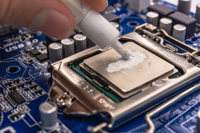
Thermal grease is a highly thermally conductive grease used to help dissipate heat from components and electronic devices that generate high heat.

It is used at the connection between a heat source that generates heat and a device that diffuses heat, such as a heat sink.

Uses of Thermal Grease

Thermal grease is used in semiconductor devices, such as power transistors, CPUs, and GPUs, to dissipate heat generated by electrical resistance quickly. Cooling these devices is essential because excessive heat can degrade device performance and cause device failure.

In personal computers, it is used to improve heat conduction between the CPU and the heat sink. They are also used in ECUs in hybrid and electric vehicles to improve the speed of heat dissipation of electronic devices. It is also used in LED lighting and other devices with high luminance or large size for the purpose of heat dissipation of electronic devices.

Principle of Thermal Grease

At the joint between a heat source and a heat sink or other heat-dissipating component, there are slight distortions of the joint surface and minute irregularities on the joint surface. This generally results in an air gap or space between the two.

Since air is extremely adiabatic, the thermal resistance of the junction is extremely high, which reduces the efficiency of heat transfer during heat dissipation. Thermal grease will fill these gaps and spaces, thereby maximizing heat transfer at the junction.

Structure of Thermal Grease

Thermal grease is made by dispersing inorganic particles with high thermal conductivity in a viscous, low-volatility oil-like component (grease) to achieve high thermal conductivity. Because of its high viscosity and easy handling, it is used in a wide range of fields related to heat dissipation and heat conduction.

The characteristics of thermal grease and its thermal conductive filler are as follows:

1. Grease

Silicone grease is often used because of its low-viscosity change with temperature. Silicone grease is characterized by its high heat resistance, chemical stability, and excellent water resistance. For this reason, it is widely used as a sealing material and adhesive, in addition to high-temperature environments and lubrication applications.

Since thermal grease is often exposed to high temperature environments, silicone grease is one of the most suitable materials because of its low viscosity change, high heat resistance, and chemical stability.

2. Thermally Conductive Filler

In thermal grease, metal or metal oxide particles with high thermal conductivity are mixed into the base grease. Metal particles such as aluminum, copper, silver, or metal oxide particles such as alumina, magnesium oxide, or aluminum nitride are used. These are dispersed in a manner appropriate to their respective particle diameters.

When metallic particles are used, not only thermal conductivity but also electronic conductivity is exhibited. Therefore, for applications where electronic conductivity is not desired, thermal grease using metal oxide particles is the only choice. In addition, metal oxide particles are often used due to their chemical stability, as metal is easily oxidized and its physical properties tend to change.

The ratio of these two materials mixed together determines the electrical properties and thermal conductivity. Based on the ratio, the properties of each thermal grease will vary. For example, thermal grease with a high concentration of filler has a higher thermal conductivity than one with a lower concentration.

Also, thermal grease has the property of degrading and hardening over time, even though it has moderate viscosity immediately after application. Depending on the difference in expansion coefficients of the materials to be joined, cracks may appear, resulting in reduced thermal conductivity characteristics.

Other Information on Thermal Grease

How to Use Thermal Grease

The basic instructions for using thermal grease are as follows:

1. Cleaning
Before applying thermal grease, the area to be coated must be cleaned. If there is a dirt or oil film, use detergent or solvent to remove it. 

2. Applying Thermal Grease
Take out an appropriate amount of thermal grease and apply it to the desired area. The role of thermal grease is to fill the gap in the air layer and conduct heat efficiently. Excessive amount of thermal grease may cause poor heat transfer due to the increased thickness and longer heat conduction distance, and may cause size defects in the assembly of the component.

3. Confirmation After Application
After applying thermal grease, check that the applied area is sufficiently covered with thermal grease. It is also important to wipe off any excess thermal grease.

4. Assembly
Assemble the necessary parts at the locations where thermal grease has been applied. When assembling, it is important to do so in the correct order, referring to the instructions.

カテゴリー
category_usa

Conveyor

What Is a Conveyor?

A conveyor is a device used to transport workpieces to specific locations.

Conveyors come in various types, such as roller, belt, and chain conveyors, each based on different drive systems. Selection depends on the specific application and ease of maintenance.

They are primarily used in distribution and factory facilities, with automated conveyors being widely employed to enhance efficiency in the logistics industry and beyond.

According to JIS standards, a conveyor is defined as “a machine that continuously transports loads.”

Conveyor Applications

Conveyors are used in a broad range of industries, particularly in logistics and manufacturing.

1. Logistics Industry

In logistics, conveyors are used for efficient sorting, loading, and unloading of goods. They enable the rapid transport of large volumes of goods, enhancing operational speed and accuracy. Distribution centers and warehouses commonly use conveyors.

2. Manufacturing Industry

In manufacturing, conveyors transport parts, materials, and products. For example, in the automotive industry, conveyors improve efficiency and assembly quality by automatically moving car bodies through various processes and supplying necessary parts. In mining, conveyors efficiently move ore from mines to processing plants and transportation facilities, reducing production costs and improving operational efficiency.

In food processing and packaging, conveyors aid in automating food transport and packaging. They are involved in washing, heating, and packaging processes, contributing to enhanced production efficiency and hygiene control.

Principle of Conveyor

Conveyors consist of a power source, a conveying medium, and a trestle.

1. Power Source

The power source drives the conveyor, often using electric power with motors selected based on conveyor capacity and torque. Three-phase motors are used for high-capacity conveyors.

2. Conveying Medium

The conveying medium, such as belts, chains, or buckets, transports the goods. The choice of medium depends on the application and the material being conveyed.

3. Trestle

The trestle provides robust support for the conveyor components. Typically made from steel or other metals, the trestle’s robustness increases with the conveyor’s capacity and speed.

Types of Conveyors

There are various types of conveyors, including the following:

1. Roller Conveyor

Roller conveyors use a series of rollers to transport goods. Suitable for heavy and large items like boxes and pallets.

2. Belt Conveyor

Belt conveyors use a flat belt for continuous goods transport. Ideal for small to medium-sized items, including powders.

3. Chain Conveyor

Chain conveyors use continuously rotating chains for goods transport. They are durable and suitable for heavy loads and high-temperature environments, often used in automotive and mining industries.

4. Screw Conveyor

Screw conveyors use a rotating spiral screw for material transport. Mainly used for powdery or granular materials like grain and cement. They can also mix powders during transport.

5. Bucket Conveyor

This conveyor uses a series of open-top containers mounted on a belt to transport materials like grains and powders vertically without leakage.

6. Net Conveyor

Net conveyors transport goods using a fine mesh net. In food processing, they are used for conveying goods while performing heat treatment, sterilization, or washing. Wire mesh nets are commonly used for their heat and corrosion resistance.