カテゴリー
category_usa

Power Distribution Panel

What Is a Power Distribution Panel?
Power Distribution Panel

A power distribution panel is a device that receives high-voltage electricity from a power plant, reduces the voltage, and distributes it to various endpoints, such as a polarization panel or control panel.

Often referred to as a “cubicle,” these panels are standard in most general households, distributing electricity from the main panel to lighting, electrical outlets, and other equipment.

Control panels, an integral part of the system, manage the automatic or manual control of motors, pumps, electric motors, and heaters. They usually handle low voltages like 100 V, 200 V, and 400 V and are equipped with ammeters, lamps, switches, etc., on their door surfaces.

Uses of Power Distribution Panels

Power distribution panels are primarily installed in large buildings such as office buildings, stores, and factories with high-voltage power contracts. These panels receive high-voltage electricity (6,600kV to 7,700kV) and convert it to lower voltages suitable for powering production facilities and communication equipment.

Ordinary households, having low-voltage power contracts, typically do not require power distribution panels. These panels are often housed in box-like structures, approximately the size of a storage shed, and are usually installed outdoors on rooftops or in parking lot corners.

Principle of Power Distribution Panels

Power distribution panels function by receiving high-voltage electricity and distributing it at lower voltages. High-voltage transmission minimizes losses, and thus, large facilities such as office buildings and factories receive electricity directly from power plants at high voltages.

For safety, the equipment is designed to protect wiring from contact with foreign objects, people, and animals, and to prevent leakages and short circuits. In case of disasters like fires or earthquakes, the design minimizes damage to the equipment.

Types of Power Distribution Panels

Power distribution panels vary widely in application and are classified into distribution boards, monitoring boards, control boards, and terminal boards.

1. Distribution Board

A distribution board is a cabinet containing switchgear and circuit breakers, distributing power to various facilities like lights and outlets. It’s designed for safe use, even by individuals without electrical knowledge, and typically features a protective board covering all parts of the circuit breaker except the knobs.

2. Monitoring Panel

A monitoring panel centrally manages data from various monitored objects spread across a facility.

3. Control Panel

Control panels manage the power supply to electric motors for air conditioning, sanitation, fire protection, etc., and are housed in cabinets containing necessary operational, protective, and monitoring equipment. These panels often have ammeters, lamps, switches, etc., on their door faces.

4. Terminal Board

A terminal board is used at electrical circuit connection points and test cutoff points, featuring numerous terminals for installation.

How to Select a Power Distribution Panel

Power distribution panels are typically installed in large facilities like factories, schools, and buildings with high-voltage contracts. In contrast, they are not necessary in standard homes with low-voltage contracts. The cost of electricity is generally higher under a low-voltage contract than a high-voltage one.

Almost all buildings, including houses and condominiums, have distribution boards to distribute electricity to each room. These boards are crucial for preventing risks like electrical leakage and ensuring safety. Large buildings often have both distribution panels and power distribution panels.

Structure of Power Distribution Panels

Power distribution panels combine monitoring and control equipment with main circuit equipment, mounted on a panel to facilitate control, monitoring, and protection of electrical circuits. This includes meters, switches, relays, disconnectors, circuit breakers, transformers, and load switches.

There are two main construction types: closed, where all equipment is enclosed in a box, and open, where equipment and steel frames are exposed. Closed types have become more common due to their safety, factory-assembled reliability, and ease of installation.

The panels include devices for controlling and monitoring electricity, such as meters, and circuit breakers for interrupting the electric current in case of abnormalities in the electrical circuit.
カテゴリー
category_usa

Parts Washers

What Is a Parts Washer?

Parts washers are machines that clean parts produced in factories and other facilities. There are a wide variety of products, from small to large parts that are compatible with various cleaning methods. Cleaning methods include ultrasonic, vacuum, and jet cleaning. The cleaning method is determined according to the type of contamination and parts. There are also a variety of installation methods for parts to be cleaned, including automatic transport and manual movement.

In addition to cleaning, some models are equipped with air blow drying and vacuum dryers.

Uses of Parts Washers

Parts washers are used to clean a wide variety of parts, from small to large. In some cases, high water pressure is used to clean and deburr parts at the same time.

Ultrasonic cleaning is used to clean fine parts, such as semiconductors.

Cutting parts for electronics and precision parts, and smaller parts for automobile engines and undercarriages, are often placed in a basket and rotated like a washing machine for cleaning.

Large workpieces are brought in one by one and cleaned by jetting, etc.

Principle of Parts Washers

The principle of parts washers depends on the model but is often similar to that of dishwashers or washing machines. Parts are placed in a drum and rotated with water and detergent to remove dirt.

Parts washers also offer a variety of cleaning methods. Each cleaning method is selected for its unique characteristics.

Jet cleaning is a method that uses high-pressure jets of water and detergent to remove dirt. Water-soluble alkaline detergents may be used, but hot water can be used for powerful degreasing.

Vacuum cleaning is a method in which air is exhausted from a chamber made of metal and the pressure is lowered to remove dirt. This method can remove even the smallest dirt that is stuck in small holes.

Deaeration cleaning uses higher air pressure than vacuum cleaning, but the same principle of degreasing is used. Since it does not require as expensive equipment as vacuum cleaning, costs can be kept low.

Ultrasonic cleaning removes dirt by immersing parts in water and applying ultrasonic waves to remove dirt. Oil and hard-to-remove dirt can be removed without rubbing. It is also used to clean fine particles from semiconductors, etc.

カテゴリー
category_usa

Carriers

What Is a Carrier?

Carriers

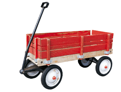
Carriers are vehicles designed for the transportation of materials, crops, and goods. Their load capacity varies based on their design, ranging from small manually operated models to larger, engine-driven vehicles capable of road travel with a seated driver.

Applications of Carriers

Widely utilized in construction sites, agricultural fields, and livestock farms, carriers enhance work efficiency by reducing the trips required to transport materials between locations. Available in various configurations, carriers can feature tiltable beds for easy unloading of materials like earth and sand, and come in both manual and engine-driven models. Specialized carriers, including those with lift-equipped cargo beds and those made of stainless steel, cater to specific transportation needs, such as compost hauling under harsh conditions.

Operating Principles

Carriers operate using either a crawler or wheel drive system:

  • Crawler: Featuring an infinite track, this type excels on uneven terrains, such as construction sites and farmland, providing stability on slopes and unprepared surfaces.
  • Wheel Drive: Wheel-driven carriers offer enhanced maneuverability, making them ideal for narrow or confined spaces where quick movement is required.

Designs of Carriers

The design of a carrier’s bed significantly influences its load capacity:

  • Flat Body: With no roof and a flat bed, this design accommodates tall loads but requires protection against the elements and securement for safe transport.
  • Van Body: Enclosed with aluminum, van bodies protect cargo from weather, making them popular for commercial use and valuable in disaster response scenarios.
  • Refrigerated and Freezer Trucks: Insulated to maintain low temperatures, these vehicles are essential for transporting perishable goods while preserving freshness.
  • Wing Body: Featuring sides that open like wings, these vehicles facilitate easy loading and can transport a diverse range of cargo sizes efficiently.
  • Towing Truck: Specialized for hauling large quantities on articulated trailers, offering high transport efficiency.
  • Special Work Vehicles: Equipped with specific functions for specialized tasks, enhancing their utility in various industries.

Categories of Carriers

Carriers are classified by size into:

  • Light-Duty Trucks: Vehicles under specific dimensions and with a maximum load capacity of up to 3,000 kg, suitable for smaller transport tasks.
  • Medium-Duty Trucks: With dimensions and load capacities that bridge the gap between light and heavy-duty vehicles, ideal for a wide range of transportation needs.
  • Heavy-Duty Trucks: Designed for the heaviest loads, requiring specialized licenses due to their size and capacity.
カテゴリー
category_usa

Planetary Gear Speed Reducers

What Is a Planetary Gear Speed Reducer?

A planetary gear speed reducer is a device that uses planetary gears to reduce the speed of an input shaft to a lower output speed. It comprises a central sun gear, multiple planetary gears that orbit the sun gear, an internal ring gear that encloses the planetary gears, and a carrier that connects the planetary gears. This arrangement allows for a compact design with input and output shafts on the same axis, accommodating multiple planetary gears for efficient power distribution.

Applications of Planetary Gear Speed Reducers

Planetary gear speed reducers are integral to machinery requiring high power transmission in a compact space. They are prevalent in automotive transmissions, particularly in torque converter automatic transmissions and 4-wheel drive vehicle center differentials. Beyond automotive applications, they power industrial machines like shield excavators and gantry cranes. Notably, they also facilitate the unique transmission system of the Toyota Prius, dividing engine output between driving and power generation.

Operating Principle

The operation of a planetary gear speed reducer is based on the fixed internal ring gear and the rotation of the sun gear, which drives the planetary gears in an orbital motion. This motion, taken as the output, allows the device to function as a reducer. The carrier, moving coaxially with the input shaft, distributes the input force among multiple planetary gears, enabling the transmission of substantial power in a compact form.

Varieties of Planetary Gear Speed Reducers

Planetary gear speed reducers are categorized by the type of gears they employ. Innovations include roller-based systems, trochoidal curved gears, and mechanisms linking the outer diameter with rollers flexibly. Each variant offers unique advantages, tailored to specific operational requirements.

Advantages and Considerations

While planetary gear speed reducers excel in delivering high reduction ratios, substantial torque capacity, and potential use as speed increasers in a compact, low-noise package, they also present challenges. Their complex design demands precision in assembly and incurs higher costs and maintenance needs. Choosing a planetary gear reducer requires careful consideration of its benefits and limitations relative to the intended application.

Design Considerations

Designing a planetary gear speed reducer necessitates advanced technical skills due to its intricate structure. Considerations include managing the outer diameter based on the reduction ratio and ensuring no interference between the sun and planetary gears.

Determining Reduction Ratio

The reduction ratio of a planetary gear speed reducer is influenced by the gear tooth counts of the sun and planetary gears. Achieving higher reduction ratios involves balancing the size of these gears, mindful of the structural arrangement and power transmission efficacy. Additionally, the orbital motion of the planetary gears introduces centrifugal forces that must be meticulously managed to prevent interference with the internal gears.

カテゴリー
category_usa

Speedometers

What Is a Speedometer?

Speedometers

A speedometer is an instrument for measuring the speed of a moving object. Accurate measurement can only be made from the front of a moving object, and not from the side of a moving object.

Speedometers are used in baseball to measure the velocity of the ball thrown by the pitcher, and they are installed in front of the pitcher to measure the speed of the ball.

Some speedometers can also measure the acceleration of an object, so they can be used to measure the acceleration of a car.

Uses of Speedometers

Speedometers are used to measure the speed of moving objects, including baseballs, but they are especially commonly used to measure the speed of automobiles.

When a police officer is trying to enforce a speeding ticket, he or she needs evidence that a violation has occurred. Speedometers are used as evidence of this. Speedometers are also installed on roads to identify vehicles that are speeding. In this case, they are used as automatic speeding control devices, also called an “Orbis speed camera,” and when a speeding vehicle is identified, it is photographed and its license plate number and other information is captured in the photograph.

Principle of Speedometers

Speed measuring devices measure the radio waves that are reflected after they are emitted onto an object approaching or moving away from the front. As known as the Doppler effect, the wavelength of sound or light reflected from a moving object changes, and the speed measuring device uses this principle to calculate the speed based on the change in wavelength of the reflected radio waves.

In the Doppler effect, the frequency of a radio wave reflected from an approaching object increases, while the frequency of a radio wave reflected from an object moving away decreases. For this reason, the speed of objects that can be measured can be up to the speed of light, but in reality, the majority of applications are for speeds up to several hundred kilometers per hour.

When determining acceleration, measurements are taken twice. That is, the acceleration is calculated from the velocity obtained in the first measurement and the velocity obtained in the second measurement. When a baseball pitcher throws a ball, he does not accelerate but decelerates from the moment he throws it. Of course, this deceleration can be calculated in the same way as acceleration, but it is not measured because it is not necessary. However, a car, for example, accelerates after starting, so speedometers that can measure acceleration are used to measure this acceleration.

カテゴリー
category_usa

Reverse Osmosis Systems

What Is a Reverse Osmosis System?

Reverse Osmosis Systems

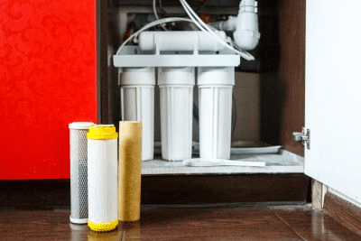
Reverse osmosis membrane water purifiers are water purifiers that use a semi-permeable membrane that allows only water molecules to pass through.

It is also known as a reverse osmosis (RO) water purifier. Semi-permeable membranes have tiny pore sizes (less than 2 nanometers) and can remove substances (minerals, bacteria, viruses, trihalomethane, chlorine, environmental pollutants, heavy metals, radioactive substances, etc.) that cannot be removed by ordinary water filters (hollow fiber membrane, activated carbon, etc.).

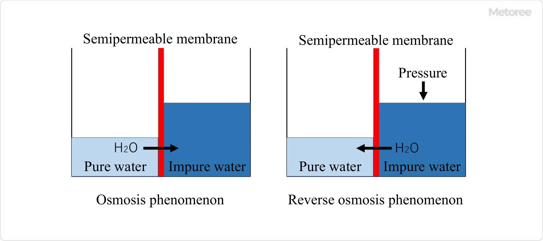
Reverse osmosis systems use the phenomenon of reverse osmosis. Reverse osmosis applies pressure to the aqueous solution (raw water) to move water molecules through a semi-permeable membrane to produce pure water that is as close to 100% pure as possible. The resulting pure water does not contain any minerals (calcium, magnesium, inorganic salts, etc.) and is therefore so-called “super” soft water.

Uses of Reverse Osmosis Systems

Reverse osmosis systems were originally developed to desalinate seawater for drinking water, but have since been used for a variety of purposes. These include recycling domestic wastewater into drinking water in outer space, purifying highly pure water for experiments and medical use, ensuring drinking water during disasters, and softening hard water.

Especially in the medical industry, the technology used in reverse osmosis systems is applied as water treatment equipment in dialysis and is an indispensable technology. In 2011, due to the accident at the Fukushima Daiichi Nuclear Power Plant after the earthquake, radioactive materials above the standard values were detected in tap water in the Tokyo metropolitan area, including the Kanamachi Water Treatment Plant.

This led to the focus of attention on reverse osmosis systems, which can remove radioactive substances from tap water.

Principle of Reverse Osmosis Systems

3463_Reverse-Osmosis-Systems_逆浸透膜浄水器-1.png

Figure 1. Principle of reverse osmosis membrane water purifiers

Reverse osmosis systems use semi-permeable membranes that allow only molecules and ions below a certain size to pass through. The semipermeable membrane is made of recycled cellulose, acetyl cellulose, or polyacrylonitrile. Osmosis is a phenomenon in which water molecules move from the low-concentration aqueous solution (pure water) to the high-concentration aqueous solution (impure water) through the semipermeable membrane when the high-concentration aqueous solution (impure water) is on one side and the low-concentration aqueous solution (pure water) is on the other side.

Reverse osmosis systems use this principle. Reverse osmosis systems are generally unable to convert raw water containing impurities into 100% pure water, resulting in wastewater that is approximately twice the amount of pure water that can be produced.

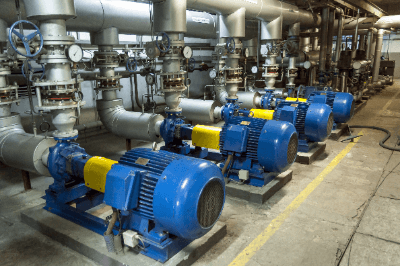
In addition, when treating aqueous solutions (raw water) that contain many impurities, such as seawater, pretreatment is necessary according to the concentration and turbidity of impurities in the raw water because semipermeable membranes quickly become clogged if raw water is passed directly through RO modules, which cause reverse osmosis. Furthermore, if there is a high concentration of impurities (ions, etc.) that cannot be removed by pretreatment, it is necessary to increase the pressure applied to the aqueous solution side, which requires the use of a pump to pressurize the solution.

Other Information on Reverse Osmosis Systems

1. Water Treatment Process of Household Reverse Osmosis Systems

3463_Reverse-Osmosis-Systems_逆浸透膜浄水器-2.png

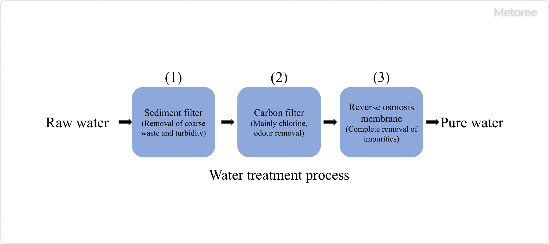
Figure 2. Water treatment processes in household reverse osmosis membrane water purifiers

In the case of household reverse osmosis systems, raw water is first passed through a cement filter. The pore size of the cement filter is usually about 1 to 5 μm. Next, the treated water is passed through an activated carbon (carbon) filter to remove chlorine and odors.

The semipermeable membranes normally used in reverse osmosis are sensitive to chlorine and require chalky (chlorine) removal. The treated water is then passed through a reverse osmosis membrane module to produce pure water through the reverse osmosis phenomenon.

2. Advantages and Disadvantages of Reverse Osmosis Systems

Reverse osmosis systems have the advantage of producing extremely pure water, but there are disadvantages, such as the inability to convert 100% of raw water to pure water (wastewater is generated). There is also the need for pressurization (pump), and the need for appropriate pretreatment depending on the raw water conditions. In addition, reverse osmosis membrane water purification systems have some disadvantages.

In addition, reverse osmosis systems are more expensive than other water purifiers because of their complex system structure due to the principle of reverse osmosis. Therefore, it is necessary to select a purified water production system in consideration of the purpose of use and the level of purity of water required.

カテゴリー
category_usa

Liquid Pumps

What Is a Liquid Pump?

Liquid Pumps

Liquid pumps are pumps used to supply and transfer liquids.

Liquid pumps can move liquids from low to high or from container to container.

Pumps of various sizes and performances are used for a wide range of purposes, from household refueling pumps to large-scale factory production lines and drainage lines.

Uses of Liquid Pumps

Liquid pumps are used in many locations, such as:

  • Household oil feed pumps (manual and electric)
  • Equipment used in chemical experiments
  • Medical fields (intravenous drips, dialysis machines, artificial heart-lung machines, etc.)
  • Liquid transfer in food production lines
  • Liquid transfer in pharmaceutical production lines
  • Water supply and sewage facilities
  • Sewage treatment facilities
  • Factory wastewater transfer systems

Pumps come in a wide variety of structures and sizes depending on their usage.

Pumping liquid without leaking it outside is the basic performance requirement, but pumps with optimal characteristics are selected according to the intended use, such as for medical equipment where a certain amount of liquid must be injected within a certain period, or for pharmaceutical or food production lines where accurate metered dosing is required for a given process.

Principle of Liquid Pumps

The basic principle of operation is the same for all pumps: pumping liquid by repeating the “suction” → “discharge” process.

Liquid pumps are broadly classified into the following two types in terms of structure:

  • Non-displacement Pumps
  • Positive Displacement Pumps

Non-displacement pumps are constructed to move liquid by rotating an impeller inside an enclosure. They have the following characteristics:

  • High-speed rotation can create a continuous flow.
  • Suction and discharge pressures are relatively low.
  • Capable of pumping large volumes of liquid, but the flow rate fluctuates depending on the nature of the liquid.

A positive displacement pump has a structure that moves liquid by changing the volume in a compartment (small room) inside the housing and has the following characteristics:

  • High suction pressure and discharge pressure can be achieved.
  • An accurate setting of discharge pressure and flow rate is possible.
  • Liquid transfer volume is relatively small.

Volute pumps, axial flow pumps, and semi-axial flow pumps are classified as non-volumetric pumps.

The following types of positive displacement pumps are available:

  • Types that perform suction and discharge using the linear motion of internal parts (piston pumps, plunger pumps, diaphragm pumps)
  • Types that perform suction and discharge using the rotation of internal parts (gear pumps, rotary pumps, vane pumps)
カテゴリー
category_usa

Near Infrared (NIR) Cameras

What Is a Near Infrared (NIR) Camera?

A near-infrared (NIR) camera is a specialized device capable of capturing images in the infrared wavelength range, specifically from 700 nm to 2,500 nm (0.7 to 2.5 μm), which is beyond the capabilities of standard cameras. This type of camera exploits the unique absorption and reflection properties of various materials to visualize scenes or objects invisible to the naked eye, making it invaluable across numerous applications, from product inspection to agricultural analysis.

Applications of Near Infrared (NIR) Cameras

NIR cameras are used in many fields for their ability to capture non-visible light. They are instrumental in:

  • Evaluating the freshness of agricultural produce and detecting contaminants in food products.
  • Analyzing pharmaceutical compositions and assessing moisture content in various substances.
  • Identifying flaws in materials such as wood and assisting in the sorting of recyclables.

Principles of Near Infrared (NIR) Cameras

NIR cameras operate on the principle that different materials reflect and absorb near-infrared light to varying degrees. By illuminating a subject with NIR light and capturing the reflected wavelengths, these cameras can distinguish between substances that appear identical under visible light, thereby revealing hidden details or compositions.

Characteristics of Near Infrared (NIR) Cameras

NIR cameras are distinguished by their ability to visualize the interaction of near-infrared light with various materials. This capability allows for the detailed examination of organic and inorganic substances without the limitations posed by visible light, offering insights into properties and conditions not otherwise observable.

Differences Between NIR and Far Infrared (FIR) Cameras

While NIR cameras are adept at capturing images based on light reflection and absorption, FIR cameras are designed to detect thermal emissions, making them suitable for security, surveillance, and thermal analysis applications. The choice between NIR and FIR cameras depends on the specific requirements of the task at hand, including the need for day or night operation and the types of materials or phenomena being observed.

Imaging with Near Infrared (NIR) Cameras

Images captured with NIR cameras reveal characteristics of objects that are not discernible with visible light, such as differences in material composition and moisture content. This ability to distinguish between similar-looking substances based on their infrared signatures enables precise analysis and inspection across various industries, enhancing quality control and research capabilities.

カテゴリー
category_usa

Rotary Presses

What Is a Rotary Press?

Rotary Presses

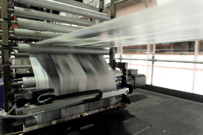
A rotary press is one of the printing presses in offset printing, capable of handling double-sided printing and multi-color printing at high speed. A roll of paper (take-up paper) is set, the printing plate is set in a rotating cylinder, and the paper is printed while being passed between the cylinders while being rewound on the other side of the press. This type of printing excels at printing large quantities of items, such as newspapers and flyers. After printing, the paper is cut to a predetermined size and finished. The printing press is very large. Rotary press printing is prone to paper shrinkage due to the use of a high-temperature dryer to dry the ink after printing. The size of the rolls that can be set is limited by the rotary press.

Rotary press printing presses that use cut sheets of paper are called sheet-fed presses, whereas rotary press printing presses use rolls of paper.

Uses of Rotary Presses

Offset printing is used for low-cost, high-volume printing and is often used to print magazines, newspapers, flyers, etc. with large circulation. Also used for posters, etc. Relatively thin paper is used. Special ink dries quickly with heat, so post-processing is unnecessary, and high-speed processing is possible by dryer processing at high temperatures after printing.

Principle of Rotary Presses

A roll of paper is set in the rotary press, and printing is performed while the roll passes between the blank and pressure cylinders. The printing plate (aluminum plate) is set in a part called the plate cylinder of the rotary press. Fountain solution and ink are applied to this plate, and once the ink is transferred to the blanket cylinder (blanket, a transfer roller made of resin or rubber), it is printed on the passing take-up paper. Printing is done in double-sided multi-color printing, which enables high-speed printing. To speed up ink drying, the rotary press uses heat-set ink, which dries rapidly with heat, and the ink is passed through a dryer section to dry. The hot paper is cooled by being wound onto cooled rollers in the cooling section that adjusts the tension of the web, and then the paper is folded and cut.

In a rotary press, the ink on the blank cylinder is transferred to the paper, so the paper and the plate do not come into direct contact with each other. This printing method is called offset printing. Since the plates do not touch the paper directly, there is less wear, and the long life of the plates also makes them suitable for high-volume printing.

Differences Between Rotary Presses and Copy Machines

Both rotary presses and photocopiers can reproduce originals, but each has its own advantages and disadvantages and is used for different purposes.

Copiers are generally for home and office use, with multifunction devices that include fax, printer, and scanner functions in addition to copying. They can be conveniently linked to a computer or network. Because the functions are integrated, they have the advantage of reducing equipment management costs and saving installation space. However, because they can print in full color, they are used for a wide range of purposes, including photo printing and the preparation of presentation materials.

A rotary press is not as multifunctional as a copier and is a dedicated printing machine that can print manuscripts at high speed, with one- or two-color printing being the most common type. They can print at more than 100 sheets per minute. Although it requires some space for installation and preparation such as setting up a rewinder and adjusting the machine, once a plate is made, ink is applied and the paper is crimped to print a large number of sheets, so the more sheets printed, the lower the unit price per sheet.

How to Use a Rotary Press

Printing with a rotary press consists of the following three major steps:

1. Prepress Process
This is the process from composition, design, and editing of the manuscript to be printed to plate making. Before digitalization, printing was done by typing on a transcription machine or creating plates from scanned pictures and photos.

2. Pressing Process
This is the process of printing using the plates created in the pre-press process. Printing is started after preparations such as setting the roll paper, mounting the plate, and adjustment of the ink have been made. At the beginning of printing, printing is done slowly while checking for any abnormalities such as misprinting or density, etc. After that, printing is done at a high speed by increasing the rotation speed.

3. Post-press Process
This is the process of post-processing the printed paper. Cutting is performed according to the size of the final printed product. Depending on the application, folding such as two-fold or four-fold, laminating, foil stamping, or other processing may be applied.

カテゴリー
category_usa

Ultrasonic Thickness Gauge

What Is an Ultrasonic Thickness Gauge?

Ultrasonic Thickness Gauges

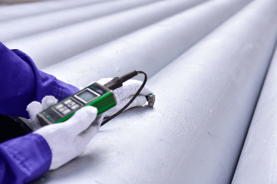
An ultrasonic thickness gauge is a device that employs ultrasonic waves to measure the thickness of an object.

It determines the thickness by measuring the time ultrasonic waves take to traverse the object. This non-destructive method is ideal for product and material quality control. The gauges are highly accurate, capable of detecting minute thickness variations and measuring the thickness of thin materials efficiently.

The operation typically involves pressing the device against the object’s surface and activating the measurement button. Many models boast digital displays and automated measurement functions. Their portability makes them suitable for on-site usage, and their compact design allows for measurements at various locations.

Uses of Ultrasonic Thickness Gauges

Ultrasonic thickness gauges find applications in various scenarios where thickness measurement is essential.

1. Manufacturing Industry

In the manufacturing sector, these gauges are crucial for measuring the thickness of materials such as steel plates and aluminum plates. They are instrumental in ensuring precision in products like automotive body panels and aircraft frames.

2. Construction Industry

In the construction field, these gauges are employed to measure the thickness of concrete in structures and floors, aiding in strength assessment and uniformity checks. They are also invaluable for detecting corrosion in metals, especially in areas like underground piping or building interiors, as they measure thickness reduction non-destructively.

Principle of Ultrasonic Thickness Gauges

Ultrasonic thickness gauges operate on the principle of measuring an object’s thickness using the travel time of ultrasonic waves. The gauge comprises an ultrasonic generator, usually made of piezoelectric or magnetic elements, transforming electrical energy into ultrasonic waves.

These waves are emitted towards the object, where they are reflected and scattered by the internal structure and interfaces. The reflected waves are then captured by a receiver, transformed back into electrical signals, and their travel time is measured.

The calculation unit computes this travel time. With pre-set ultrasonic wave velocity data for the specific material, it calculates the object’s thickness. Accurate velocity data is crucial, as ultrasonic wave speed varies with the material’s composition and density.

Types of Ultrasonic Thickness Gauges

Different types of ultrasonic thickness gauges are designed for specific applications:

1. Single-Element Ultrasonic Thickness Gauge

This gauge utilizes a single transmitter/receiver element, making it suitable for simple thickness measurements in thinner materials.

2. Dual-Element Ultrasonic Thickness Gauge

With separate transmitter and receiver elements, this gauge offers enhanced signal accuracy and sensitivity, applicable to various uses.

3. Dual Element Ultrasonic Thickness Gauge

This type has both transmitter and receiver elements in the same sensor head, ensuring more accurate measurements, particularly under high-temperature conditions and on uneven surfaces.

4. Multi-Element Ultrasonic Thickness Gauge

This gauge features multiple transmitting and receiving elements, allowing for thickness measurements on complex surfaces and shapes.

How to Select an Ultrasonic Thickness Gauge

Consider the following aspects when choosing an ultrasonic thickness gauge:

1. Object to Be Measured

Reflect on the material type and surface condition of the object. Specific materials and shapes might necessitate specialized gauges.

2. Thickness and Accuracy Requirements

Evaluate the range of thickness to be measured and the precision needed. Gauges vary in their capacity to measure ultra-thin or thick materials.

3. Operability

Usability is crucial. Consider features like user-friendly interfaces, simple navigation, and data recording functions.