カテゴリー
category_usa

Shrink Films

What Is a Shrink Film?

Shrink Films

Shrink film is a film that shrinks when heat is applied. The film is made of thermoplastic resin that can repeatedly deform with heat. In addition to having high gloss and transparency, it also has excellent water resistance, cold resistance, and mechanical strength. Applying these properties and its ability to shrink with heat to fit various shapes, it is used for packaging applications with excellent aesthetics. Shrink film is also often used to protect products and prevent tampering these days because of its irreversible nature once it is torn.

Uses of Shrink Films

Shrink film is used for a wide variety of packaging applications. It is helpful for packaging applications because of its superior design, product protection, and work efficiency.

1. Design

Because it can provide a large display area, product PR and multi-color printing are possible. It is used for boxed tissues and instant noodle packaging.

2. Product Protection and Tamper-Resistance

It is used for its superior water resistance and cold resistance, as well as for proof of unopened packages, and mainly for packaging caps.

3. Work Efficiency

It combines multiple products into one to improve work efficiency and convenience, such as yogurt, 6-packs of PET bottles, etc.

Principle of Shrink Films

This section introduces the characteristics of each material used in shrink film. The advantages and disadvantages of the six primary materials used are explained below.

1. Polyvinyl Chloride

It has excellent transparency, formability, flame resistance, and electrical insulation properties and can shrink at low temperatures. On the other hand, its natural shrinkage and fragile sealing surface are disadvantages.

2. Polypropylene

Polypropylene has excellent transparency, cold resistance, moisture resistance, and printability and has a low unit price. On the other hand, it has the disadvantage of natural shrinkage.

3. Polyethylene

Polyethylene has higher mechanical strength than polypropylene. Its good shrinkage enables large blocking packages. However, it is less transparent than other types.

4. Polystyrene

Superior transparency and heat shrinkability, but weak against impact and organic solvents.

5. Polyolefin

Polyolefin has a high shrinkage rate and is excellent for its finish, as it does not easily wrinkle or form a crease. It is also a highly convenient material with high tearing strength. Although polyolefin offers high performance, its unit price is high.

6. Polyethylene Terephthalate

Known popularly as PET, this resin has excellent transparency, mechanical strength, chemical resistance, and dimensional stability. It has various exceptional properties, but its difficulty processing is a drawback.

カテゴリー
category_usa

Cermet Trimmers

What Is a Cermet Trimmer?

Cermet trimmers are a type of circuit component known as “semi-fixed resistors” in Japanese. Unlike variable resistors, where users must adjust the resistance value each time, cermet trimmers maintain the set resistance value even after it has been changed.

Incidentally, the term “Cermet” is a blend of ceramics and metal, and it is called cermet because it is made by blending these two types of materials. For example, it includes ruthenium oxide metal particles and glass as materials.

Uses of Cermet Trimmers

Cermet trimmers are used in circuits where resistance changes infrequent. With regular variable resistors, users must adjust the resistance value using a dial or similar method each time they use the resistor. In contrast, cermet trimmers are used, for example, to calibrate the displayed value of a measuring instrument. In this case, the resistance value is adjusted to the initial setting when the instrument leaves the factory, and afterward, the instrument is used as a resistor with a constant resistance value. Cermet trimmers are also employed in industrial equipment, medical devices, household appliances, and measuring instruments.

Principles of Cermet Trimmers

Cermet trimmers fall into the category of variable resistors, which can be carbon (carbon film), metal wire wound, or thin film. Cermet trimmers have a wide range of resistance values, excellent temperature resistance, and stable characteristics. They also allow for very smooth and subtle adjustments, with relatively low levels of noise associated with the sliding motion.

The primary components of cermet trimmers are titanium and tantalum, both of which exhibit excellent corrosion resistance. Carbon is sometimes used instead of cermet in consumer products like household appliances to reduce costs. However, for its reliability, cermet is preferred in measuring instruments, communication equipment, and medical devices. The mechanical structure used to set the resistance varies from product to product, including the position of the dial used for resistance adjustment. Electrical parameters and variable resistance ranges also differ from one product to another, so selecting the right one for the application is essential.

カテゴリー
category_usa

Servo Actuators

What Is a Servo Actuator?

Servo Actuators

An actuator is a device that converts energy from a power source into some mechanical motion, such as straight-line movement, rotation, or bending. For example, a motor, a common power source, is an actuator.

A servo actuator is a specialized type of actuator used in servo systems. These systems automatically control an object’s position, orientation, speed, and force with high precision, following changes in a target value. Servo actuators are essential in guiding and controlling the movement of mechanical systems, offering precise control compared to conventional actuators.

Uses of Servo Actuators

Servo actuators, powered by electricity, are integral in controlling industrial robots and precision machinery. They are also pivotal in the operation of humanoid robot joints, driving mechanisms in food and packaging machinery, conveyor systems, and more. Their applications extend to automatic doors for trains and vehicles, hobby items like radio-controlled cars, coating equipment, and cleaning devices for liquid crystal and semiconductor fabrication.

Principle of Servo Actuators

Servo actuators, a subset of electrically operated actuators, play a pivotal role in servo systems. These systems enable precise control over an object’s position, orientation, force, and speed, adapting to changes in target values. This capability allows for the accurate application of force, speed, and angle during movement, making servo actuators vital in mechatronics and various applications such as industrial robots and precision machinery control.

カテゴリー
category_usa

Circuit Testers

What Is a Circuit Tester?

Circuit Testers

Circuit testers are tools used to measure the current, voltage, resistance, etc., of in-vehicle electrical components and batteries. Unlike current detection testers, which can only tell whether current is flowing, circuit testers can measure even numerical values such as measured current and voltage. There are two types of testers: analog testers that display these values with a needle and digital testers that show the numerical values on a monitor.

Uses of Circuit Testers

Circuit testers are used primarily for vehicle maintenance. They not only detect the energized positive wire but can also identify the negative wire and check current consumption. This capability is essential when installing a fuse of the appropriate amperage, ensuring safe and efficient operation. Additionally, circuit testers are valuable tools for verifying that relays and switches do not exceed their allowable current values.

Principles of Circuit Testers

Circuit testers are designed for convenience and ease of use, featuring a large rotary switch with 2000 counts and Japanese notation. They offer a manual DMM with a wide measuring range and include a backlight for measurements in dark environments. The testers’ DC10A range is equipped with an LCD for clear visibility. They automatically detect and measure voltage and resistance and can locate live wires in walls and ceilings. Their large, clear display ensures easy readability.

A single circuit tester unit is versatile enough for various electrical system checks, including measuring engine RPM for both direct ignition and high-tension cord types. The ultra-thin, lightweight design of the DMM makes it easily portable, and the color-coded range and switch system enhance user-friendliness. Furthermore, the holster with a test lead fixing function is convenient for measurements in challenging environments.

These testers are capable of performing a wide range of measurements, such as battery voltage, alternator charge current, and dark current. They are also useful for water temperature sensor checks, continuity tests, diode tests, noise prevention capacitor checks, and various resistance checks. Additionally, their ability to measure temperature makes them suitable for tasks like checking the temperature of air conditioner vents.

カテゴリー
category_usa

Sanitary Valves

What Is a Sanitary Valve?

The term ‘sanitary’ refers to cleanliness and is crucial in fields where hygiene is paramount, such as in pharmaceutical, food, and cosmetic industries. Sanitary piping is commonly used in these fields. Unlike piping in typical chemical plants, sanitary piping is designed to minimize liquid accumulation and has smoother surfaces.

In addition to sanitary piping, there are naturally sanitary valves as well.

Uses of Sanitary Valves

Sanitary products are characterized by their ease of disassembly. Because of this feature, they are often used in fields where they are disassembled for thorough cleaning. This is why they are used in the pharmaceutical, food, and cosmetics fields mentioned above.

For example, in the food field, finished products delivered to us must not contain any germs. Sanitary products are essential to protect consumer health.

Principle of Sanitary Valves

Sanitary valves can be broadly divided into two types: sanitary ball valves and sanitary butterfly valves.

Sanitary ball valves have a spherical valve plug. It opens and closes by rotating 90 degrees with the operation of a handle.

Sanitary butterfly valves have a disk-shaped valve disc. Operated by rotating the valve 90 degrees with a handle, the same as the sanitary ball valve, it can also use the middle opening position. Therefore, the flow rate can be adjusted. The thin valve body also allows for lightweight and compact operation.

Sanitary valves also offer significant advantages in terms of sanitation. Commonly used ball and butterfly valves have joints or rubber seats in their wetted parts. When liquid flows through them, it remains around these joints and seat rubbers. This residual liquid can promote bacterial growth and potentially cause odor issues with the rubber components.

カテゴリー
category_usa

Corrugated Tubing

What Is Corrugated Tubing?

Corrugated Tubing

Corrugated tubing is utilized to safeguard electric wires and organize wiring.

There are two types of corrugated tubes: one with slits for easy wire insertion and removal, and the other without slits to maintain airtightness.

Corrugated tubing, as the name suggests, has a corrugated shape, and its flexibility makes it an ideal wire protection material that can easily conform to wire routing. It is durable, resistant to collapsing under pressure, and suitable for both indoor and outdoor applications, depending on the material.

Typically, the color is primarily black, but for automotive applications, a noticeable orange color is used to easily identify the protection of high-voltage wires. Transparent white products are also available for medical applications.

Uses of Corrugated Tubing

Corrugated tubing is employed to shield electrical wires from wear and tear.

The insulation of an electric wire alone cannot withstand external factors such as mechanical stress or exposure to sunlight, potentially causing the wire’s conductor (core gland) to become exposed due to sheath damage. This could result in electrical leakage and even a fire hazard.

For instance, in outdoor applications, non-slit corrugated tubing is suitable for use in drainage systems. Its ease of processing, flexibility, and airtightness make it valuable for rain gutter applications on golf carts, vehicles, and as drainage piping for outdoor components of home air conditioning units.

The robust and flexible resin material provides protection against impact, abrasion, and heat. It finds application in a wide range of scenarios, used for wire protection and organization in factories, construction sites, automobiles, offices, PCs, and office automation equipment.

There are also various types of corrugated and alternative tubing designed with excellent flame and heat resistance for various applications. The tubing’s length can be easily adjusted using a cutter.

Characteristics of Corrugated Tubing

Corrugated tubing is available in two variants, with or without slits for wire entry.

1. Corrugated Tubing with Slits

Slit corrugated tubing offers the advantage of easy installation. Since it does not require pre-crimping of wire ends and can be installed after wires are in place, it reduces the overall processing time for wire end treatment.

However, it necessitates additional measures to prevent wire protrusion. In subsequent processes, PVC tape is often used to prevent cracks and to bundle or partially wrap the wires. Partial wrapping is costly and time-consuming, so it is advisable to consider designs that do not require slits.

For slitted tubing, while it is convenient for wire insertion, leaving wires exposed through the slits when bent or getting wires caught in the slits can lead to breakage. To prevent this, it is recommended to wrap corrugated tubing with slits in vinyl tape to keep the slits closed during wire installation.

2. Corrugated Tubing without Slits

Non-slit corrugated tubing eliminates the need for special measures to prevent wire protrusion. The steps required for slit-type tubing are no longer necessary, but securing the tube to the wires is still required by fastening it to a part of the wire.

The drawback is that attaching it to the wire can be challenging, and there are process limitations. Since wire threading must be done before crimping wire terminals, it impacts post-threading process efficiency.

In the case of non-slit tubing, the corrugated tubing must be threaded onto the wires before terminals are crimped. This reduces material costs and processing time. Additionally, the closed cross-section makes it less susceptible to dust and water penetration compared to slitted tubing.

Both slitted and non-slitted variants have their advantages and disadvantages and should be chosen based on specific applications and requirements. There are various inner diameters of tubing to consider based on the number of wires to be inserted.

Other Information on Corrugated Tubing

Corrugated Tubing Materials

The most common materials used for corrugated tubing are polypropylene, polyethylene, and nylon, each offering distinct price points and characteristics to suit various applications.

  1. Polypropylene: Heat resistance ranges from -50°C to 95°C. It is suitable for outdoor use due to excellent weather resistance. It is flame retardant and self-extinguishing.
  2. Polyethylene: Heat resistance is approximately -40°C to 50°C. It is used outdoors thanks to excellent weather resistance. Transparent white types are suitable for medical applications as they allow visibility inside.
  3. Nylon (Polyamide): Heat resistance ranges from -50°C to 125°C. Many products offer excellent heat resistance. It is flame retardant and self-extinguishing.

In some regions, rodents may enter equipment and chew on soft cables, leading to wire damage. Certain corrugated tubing includes a repellent that discourages rodents to prevent such damage.

カテゴリー
category_usa

Connector Caps

What Is a Connector Cap?

Connector CapsA connector cap is an accessory that protects the female (receptacle) end of a connector to prevent foreign objects from entering and damaging the connector.

They come in a variety of shapes and sizes, and contribute to data security and virus prevention. A connector cover, on the other hand, is used to protect the male part of a connector (the plug of a cable).

Both are utilized to protect different parts of the connector. It is important to note that they are used for different purposes and target different connector parts. Understanding these differences and selecting the appropriate protective accessory will extend the life of the connector and improve safety.

Uses of Connector Caps

The primary uses of connector caps are to prevent incorrect insertion, protect connector terminals, and provide security. In addition, they are used for the following purposes:

1. Prevention of Foreign Object Intrusion

Caps for connecting parts protect the mating part of connectors, and caps for connecting parts protect the part where wires are connected. These caps are placed on unused connectors to prevent dust and foreign matter from entering the coupling area. They also serve to prevent accidental contact with energized parts.

2. Prevention of Incorrect Insertion

Connector caps are a simple way to reduce the risk of accidental insertion of USB memory sticks and other devices.

3. Security Measures

Used for the purpose of preventing data leakage and virus infection.

4. As an Accessory

Connector caps may be used not only to protect connectors but also as accessories for smartphones, tablets, laptops, etc. They can be connected to the USB type or audio jack type compatible with each device to express individuality and taste. They are also often appreciated as gifts and presents.

Types of Connector Caps

There are two types of connector caps: one for the connection and the other for the wiring. There are also various types depending on the device and interface. The following are some examples:

  • For PCs
  • For PDA
  • For USB-A type
  • For USB-B type
  • For network LAN modular jack connector
  • For mobile devices
  • For card readers
  • For smart device equipment
  • For micro-type, small USB devices
  • For handy USB devices
  • For memory card readers
  • For telephone modular jack connectors
  • For VGA and DVI connectors for digital video equipment

Structure of Connector Caps

Connector caps are generally shaped to be inserted into connectors. Recently, however, a sliding type cover that is integrated with the device has been proposed.

This cover is integrated into the device itself and can be easily opened and closed as needed while protecting the connector’s terminal area. By utilizing the sliding function, the cover is out of the way, facilitating the use of the connector.

In addition, because the cover is integrated into the device itself, there is no need to worry about removing or losing it, providing adequate protection at all times. Such connector covers are very useful for improving the durability and reliability of electronic equipment. The patent highlights their applicability to a wide variety of electronic devices and is expected to find a broad market.

Other Information on Connector Caps

Differences From Connector Covers

Connector caps are used to protect the female connectors of devices. Connector covers, on the other hand, are used to protect the plug portion (male connector) of a cable.

However, since they are often referred to interchangeably, it is important to note which component is being addressed in context, in written and spoken language.

カテゴリー
category_usa

Connector Covers

What Is a Connector Cover?

A connector cover is an accessory used to protect the plug portion of a cable (male connector) and improve safety.

In addition to preventing the intrusion of foreign objects, they are also useful in terms of security by preventing accidental insertion and electrical contact. It is shaped for easy attachment and removal according to the shape of each connector.

The most common materials used are plastic-based ABS resin and polyethylene. A similar component is the connector cap.

Uses of Connector Covers

Connector covers are used to prevent incorrect insertion, protect connector terminals, and provide security.

1. Prevention of Foreign Object Intrusion

Connector covers cover the plug to prevent foreign objects such as dust and moisture from entering the connector.

2. Prevention of Incorrect Insertion

Connector covers designed in specific shapes and colors prevent accidental insertion into the wrong connector.

3. Prevention of Incorrect Wiring

Combining several connector covers of different colors can prevent incorrect wiring.

4. Security Measures

Connector covers with a lock function prevents unauthorized access and data leakage.

5. Cable Disconnection Prevention

Fixing the connector part reduces the ease of cable disconnection and improves the stability of the connection.

6. Stress Reduction

The connector cover reduces stress on the connection between the cable and connector, contributing to longer service life.

Structure of Connector Covers

Some connector covers have special shapes. For example, a type with a curved brim side creates a gap between the connector and the brim, making it easier to pull out the USB connector. Also, caps with wide brims make it difficult to see the metal surface of the connector.

Some USB connector covers have a feature that locks when inserted into the USB connector. This lock can only be released when a special extraction tool is used. This feature further reduces the risk of incorrect insertion or unauthorized access.

Types of Connector Covers

There are various types of connector covers, depending on the device and interface. The following are examples:

  • For PC cables
  • For PDA cables
  • For USB cables such as Type A, B, Mini-B, Micro-B, and C
  • For cable connectors of digital video equipment, such as VGA, DVI, HDMI, etc.
  • For network LAN and telephone modular jack cables
  • For audio and video equipment cables

Other Information on Connector Covers

Difference From a Connector Cap

Connector covers are used to protect the plug portion (male connector) of a cable. On the other hand, connector caps are used to protect the female connectors on the equipment.

However, since they are often referred to without distinction, it is necessary to note which component is being addressed in context in writing and conversation.

カテゴリー
category_usa

Core Drills

What Is a Core Drill?

Core Drills

Core drills are commonly used in construction sites to bore large cylindrical holes in materials such as concrete, plasterboard, mortar, bricks, and more.

Core drills can drill holes in various construction materials by simply changing the cutting edge. They play a crucial role in home construction for tasks like air conditioner installation, water piping, and electrical wiring. These drills can efficiently create large-diameter holes that ordinary drills cannot achieve in a single attempt.

Uses of Core Drills

Drill bits are limited in their ability to drill holes larger than 100 mm in diameter and are restricted to specific materials. Core drills, on the other hand, can be attached to electric hammer drills, allowing for the selection of cutting edges tailored to the material being drilled.

There are various types of core drill cutting edges, including the “multi-type” for diverse materials like reinforced plastic, siding, and PVC pipe, as well as the “for ALC” type, which is hard and features reinforcement striations, making it suitable for challenging materials.

Principles of Core Drills

Core drills are categorized as wet or dry type drills. Dry type drills do not require water and can be used in various environments without the need for curing. Wet processing, on the other hand, utilizes water for high-speed drilling, prolonging blade life, but necessitates proper drainage and curing conditions, along with a separate water supply facility.

In addition to the ALC and multi-type drills mentioned earlier, there are “vibration core drills,” which utilize vibration to drill holes while crushing the material, and “composite core drills,” capable of drilling holes in multiple materials simultaneously, including metal and insulation materials. Vibration drills are ideal for hard-to-machine materials and leave clean holes with minimal cracking.

Composite core drills excel in drilling holes in walls constructed from diverse materials, a task challenging for vibration-type drills, and even in wood containing nails.

カテゴリー
category_usa

Gate Valves

What Is a Gate Valve?

Gate Valves

A Gate Valve is a valve that closes a flow path by shutting off a fluid, such as a liquid or gas, with a disc (valve disc).

Generally, “gate valve” and “slew valve” are also used as synonyms. Gate valve is defined in JIS B0100 Glossary of terms for valves as “a generic term for valves in which the valve plug vertically divides the fluid flow path to open or close it, so that the fluid flow is in a straight line.

Gate valves are said to be so called because the disc (valve disc) slides into the flow path like a gate in a sluice gate and shuts it off.

Applications of Gate Valves

3606_Gate-Valves_ゲートバルブ-1.png

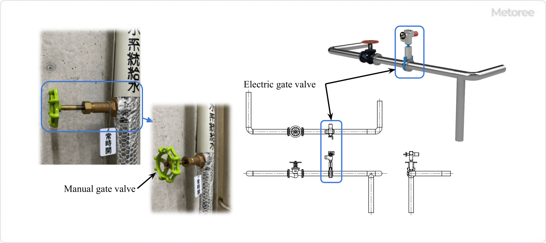
Figure 1. Example of gate valve use

Gate Valves are used in a wide range of applications, from households to general industry to academic research, because they can control fluid flow over a wide range of pressures and temperatures. Familiar examples include water meters, gas meters, and piping for water heaters.

Gate Valves, in particular, are usually used in the fully open or fully closed position because the disc vibrates when used in the middle opening position. Therefore, these valves are used for shutoff purposes as stop valves.

Generally, gate valves are installed as shutoff valves in pipelines and water supply pipelines, either permanently open or closed. Manual Gate Valves require a lot of turning of the handle, which makes opening and closing the valve time-consuming.

Therefore, when opening and closing the valve very frequently or operating it remotely, a gate valve equipped with an actuator for automatic opening and closing is used.

Principle of Gate Valve

3606_Gate-Valves_ゲートバルブ-2.png

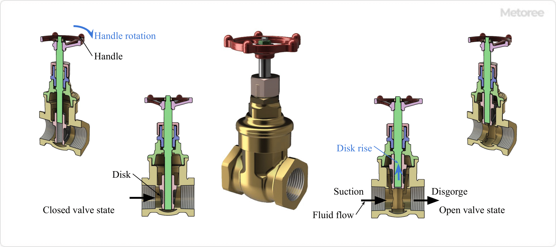
Figure 2. Gate valve open/close valve state and fluid flow

The principle of a Gate Valve is very simple: when open, the disc (plug) is lowered by the body (valve box), shutting off the flow path and closing the fluid. A closed valve, on the other hand, raises the disc and opens the flow path to allow fluid to flow.

The disc is raised and lowered by a screw mechanism on the stem, which is rotated by a handle or actuator.

1. Pressure drop across the Gate Valve

Gate Valves are often designed as full-port valves and feature an extremely small pressure drop when fully open because there is little difference in the flow path area between the inside of the body and the inlet/outlet piping, and the flow path is nearly straight.

In addition, Globe Valves, which are often used as stop valves in the same way as Gate Valves, have an S-shaped flow path inside the body, so the pressure loss at full opening is larger than that of Gate Valves.

The pressure loss is the amount of energy lost when a fluid passes through a pipe. It is caused by friction loss due to the inner wall of the pipe and the generation of turbulence.

2. Gate Valve Water Hammer Phenomenon

Gate Valves are less prone to water hammer phenomenon because they have a relatively large stroke when opening and closing, and cannot open and close abruptly. Water hammer refers to a transient rise or fall in pipe pressure caused by a sudden change in flow velocity when the valve is opened or closed rapidly.

Pressure fluctuations due to water hammer can cause the following problems

  • A sudden rise in pressure damages the piping, connected pumps, valves, and other equipment, and piping support hardware.
  • Sudden pressure drop causes deformation of the piping and secondary pressure increase due to water column separation, resulting in damage to the piping
  • Pressure fluctuations make pressure control difficult

Gate Valve Structure

3606_Gate-Valves_ゲートバルブ-3.png

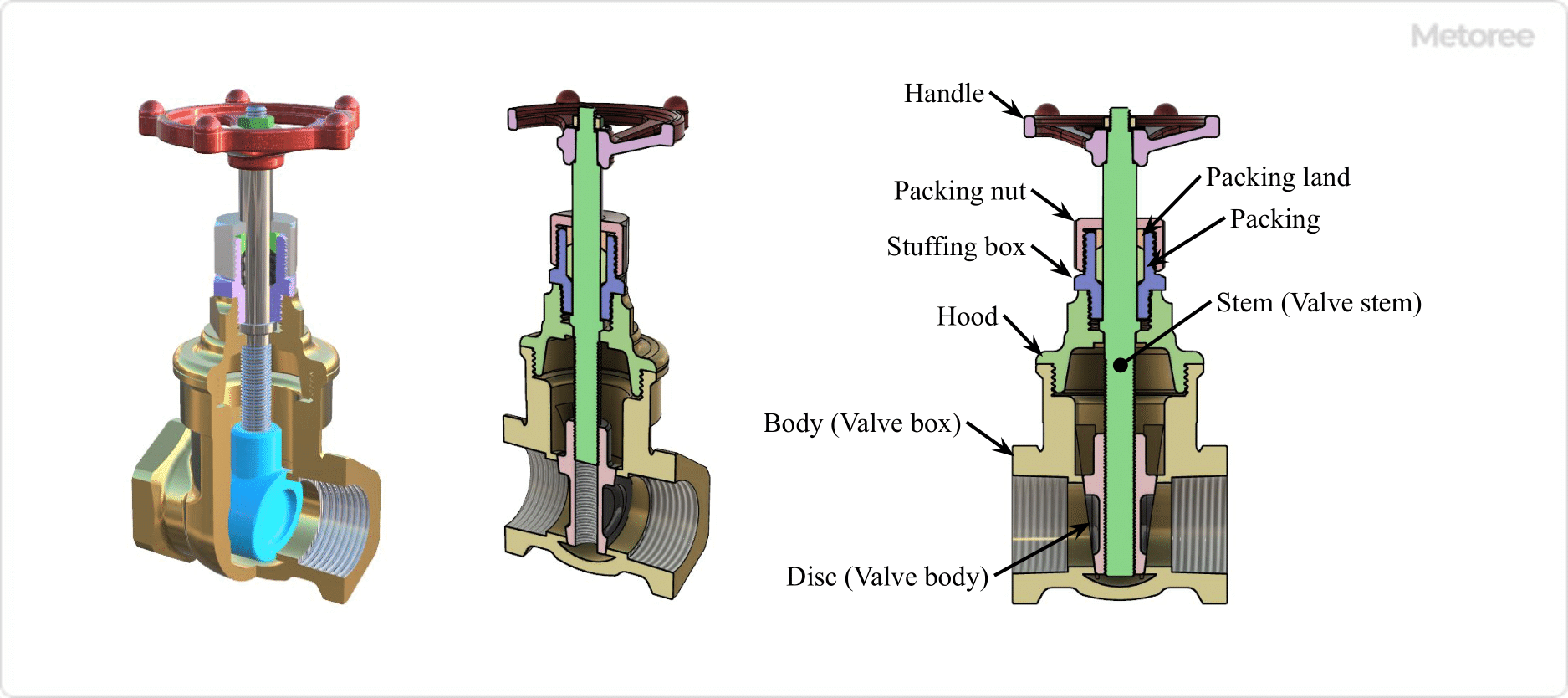
Figure 3. Structure of gate valve

Gate Valves are mainly composed of a body (valve box), a disc (valve plug), a stem (valve stem), and a handle. Gate Valves can be operated by a handle or an actuator.

The handle is attached to the stem and transmits rotation to the stem. When the valve is open, rotation of the handle causes the stem screw to rotate in a direction that raises the disc, and the opposite rotation causes the disc to rotate down when the valve is closed.

Types of Gate Valves

1. Classification by opening/closing operation method

3606_Gate-Valves_ゲートバルブ-4.png

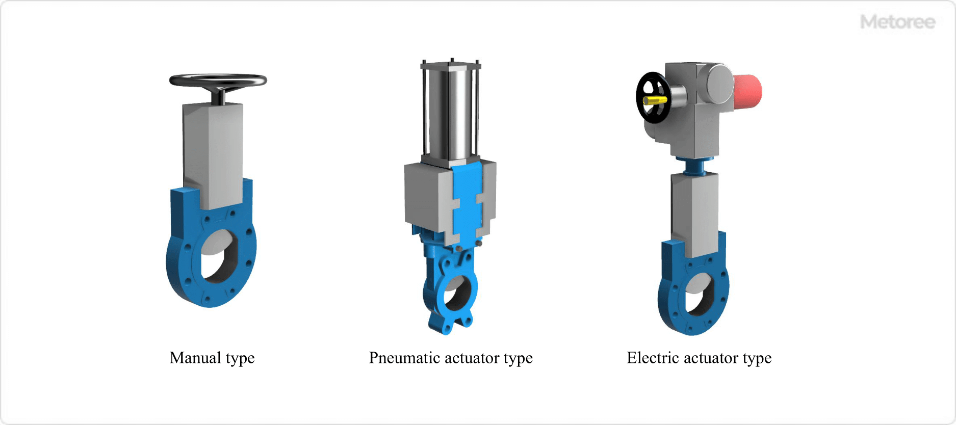
Figure 4. Gate valve operation and drive system

Gate Valves have the following three main types of operating and driving methods to open and close the valve.

  • Manual Type
    Rotating the stem with a handle, etc.
  • Air-actuated Type
    Pneumatic actuator rotates the stem
  • Electric Type
    Rotate stem by electric actuator

2. Classification by Disc Shape and Structure

Gate Valves are classified by disc shape and construction as follows

  • Parallel or wedge disc
    Discs with “parallel” or “wedge” cross section
  • Parallel Slide
    Combination of two discs parallel to each other, which, due to fluid pressure, exerts a surface pressure on the outlet side seat (valve seat) surface
  • Double Disc
    Consisting of two discs, the stem pushes the discs apart to apply pressure to the inlet and outlet seat surfaces.

3. Stem lift type and non-rising type

Gate Valves have a stem that rotates to move the disc up and down, but does not change position as the stem rotates.

Stem Ascending Type
In the stem lift type, the position of the stem or handle rises or falls with stem rotation. The degree of opening and closing can be determined by the position of the stem or handle, so the condition can be checked visually.

Also, since the stem or handle rises, a space is required to operate the handle.

Stem non-rising type
In the stem lift type, the stem or handle position does not rise or fall with stem rotation. Since the degree of opening and closing cannot be determined by the position of the stem or handle, it is not possible to visually check the state of the stem or handle.

Also, since the stem or handle does not rise, the space for operating the handle is smaller.

4. Classification by Body Material

Gate Valve materials can be classified by the material of the body. Common body materials are as follows

  • Gray cast iron JIS G5501 FC200
  • Spheroidal graphite cast iron JIS G5502 FCD400
  • Carbon steel forgings for pressure vessels JIS G3202 SFVC 2A
  • High temperature and high pressure cast steel products JIS G5151 SCPH2, SCPH21
  • Stainless steel castings JIS G5121 SCS13A, SCS14A
  • Copper and copper alloy castings JIS H5120 CAC406 Bronze castings class 3
  • Copper and copper alloy rods JIS H3250 C3771 Brass for forging

Body materials are selected based on the following requirements. For details, refer to each manufacturer’s catalog, etc.

  • Fluid type, pressure, temperature, flow velocity, and presence/absence of impurities
  • Corrosion resistance required or not
  • Applicable regulations and standards
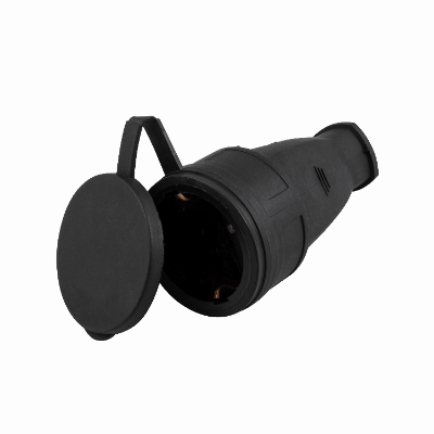