カテゴリー
category_usa

Strain Gauges

What Is a Strain Gauge?

Strain Gauges

A strain gauge is a measuring instrument used to measure the strain of an object. Strain refers to the amount of deformation that occurs in a material when an external force is applied to it. Measuring strain is essential for determining stress levels and evaluating the strength and reliability of a structure.

A strain gauge sensor detects the strain in a material, and this minute voltage signal is then input to a strain gauge to measure the extent of the strain. Strain gauges are capable of performing multi-channel measurements.

Uses of Strain Gauges

Strain gauges are indispensable measuring instruments used to ensure the strength and reliability of various structures. In addition to measuring stress, strain gauges can also be used to measure physical quantities such as temperature, pressure, load, and displacement.

Due to their versatility, strain gauges find applications in a wide range of industries, including automotive, industrial machinery, electronics, and metal and steel. For example, hydraulic excavators operate in challenging conditions, such as soil excavation and rock breaking. Consequently, strain gauges are used in research and development to assess the structural strength of such equipment.

Principles of Strain Gauges

There are various types of strain gauges, but we will introduce the principle of strain gauges that are connected via a bridge circuit.

Firstly, strain gauges are employed to detect the strain in an object. Strain gauges function on the principle of altering electrical resistance as the structure expands and contracts due to strain. This change in electrical resistance is measured to determine the strain. Subsequently, within a bridge circuit, the electrical resistance observed by the strain gauge is converted into a voltage change. This signal is then transmitted to the strain gauge. Given that the voltage obtained from the bridge circuit is minute, it is amplified using a built-in amplifier. The amplified signal is converted into digital form (analog-to-digital conversion), and the data is output to a computer. Some strain gauges come equipped with a built-in bridge circuit.

Strain gauges are capable of measuring static strain (steady-state strain) as well as dynamic strain (strain occurring at frequencies of up to several hundred kilohertz, often due to impacts and other dynamic events).

カテゴリー
category_usa

Forming Machinery

What Is Forming Machinery?

Forming Machinery

Forming machinery is a processing machine capable of performing multiple processes such as pressing, bending, and cutting of wire and plate materials, such as coils, in a single machine. It can continuously produce parts such as springs, coils, clips, and rings.

Within the category of forming machinery, there is a specialized machine for producing spring parts known as a wire-forming or spring-forming machine.

Recently, these machines have evolved to handle a wider variety of processing tasks, including integrated processes like swaging, component assembly, welding, header processing, and forging.

Uses of Forming Machinery

Forming machines are used in the manufacturing of springs, such as compression coil springs and leaf springs, commonly found in automobiles, home appliances, various construction materials, industrial machinery, agricultural machinery, and stationery.

Many of these machines can handle wire diameters as small as several millimeters, and they are used to manufacture a wide range of parts, including snap pins, retaining pins, hose bands, rings, circlips, snap rings, hose clips, and wire clamps.

In some cases, parts that were conventionally fabricated using dies and press working have been transitioned to forming machinery to reduce production costs.

Principles of Forming Machinery

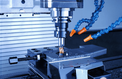
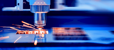
The processing process of forming machinery unfolds as follows: Initially, a feed device steadily supplies plates, coils, and other wire materials. A stamping device then shears and presses the materials, creating holes and forming them. Subsequently, multiple forming machines are employed to shape complex bends and three-dimensional forms, and additional processes can be performed in a single pass as required.

Utilizing forming machinery results in reduced material wastage and manufacturing costs through continuous processing. Moreover, in comparison to progressive presses with similar functionalities, forming machines feature a more straightforward structure, contributing to reduced die costs for the processing machine.

Initially used for mass production of simple products, forming machinery has become increasingly sophisticated with advancements in technology. It can now be integrated with NC (numerically controlled) machines to produce complex-shaped parts at a lower cost.

カテゴリー
category_usa

Milling Machinery

What Is Milling Machinery?

Milling Machinery

Milling machinery is primarily used to cut hard materials such as metal into desired shapes. In terms of shaping materials, milling machinery is similar to a lathe, but with a key distinction: while a lathe rotates the material, milling machinery employs a rotating blade or drill. This fundamental difference sets milling machinery apart from lathes.

Uses of Milling Machinery

Milling machinery serves as a machine tool for shaping materials into desired forms. Its primary function is material removal, allowing it to sculpt shapes similar to those of sculptures. Additionally, by attaching a drill or other tool, milling machinery can be used for drilling holes or performing various operations at specific locations. The utility of milling machinery varies based on the range of motion of the main spindle to which the cutting tool is attached. General milling machinery is categorized as three-dimensional milling machinery and can be employed for machining three-dimensional shapes from surfaces or radiused surfaces. Milling machinery is highly versatile and efficient, capable of handling both external shaping and drilling operations in a single machine.

Principles of Milling Machinery

This section outlines the operational principles and types of milling machinery. In milling machinery, the material is securely fixed on the table and remains stationary. Instead, the spindle, with the cutting tool attached, rotates and moves in three planes (X, Y, and Z) to shape a three-dimensional object. There are two primary types of milling machinery: “Bed Type” and “Knee Type.” Here are the specific movements for each:

  • Bed Type: In the bed type, the spindle can move vertically in the Z direction, while the table moves in the XY plane to manipulate the material. The bed type is particularly advantageous for mass production.
  • Knee Type: In the knee type, the table shifts the material both vertically and horizontally without moving the spindle. It is considered the most versatile type of milling machinery. The role of milling machinery varies based on the installed cutting tool. Here are some common examples:
  • Front Facing Milling Machine: This is the most common milling tool used for cutting flat surfaces. It offers high cutting capacity and can be reused by replacing the cutting edge.
  • Side Milling Cutter: A milling tool with cutting edges on the outside, primarily used for cutting side surfaces. Also known as a side cutter.
  • End Mill: A versatile cutting tool with functions similar to a drill, capable of perimeter machining, drilling, grooving, and more. It is widely used for various machining operations.

Milling Machinery Tools

Milling machinery can perform a variety of machining operations by changing the spindle tool.

The most common type of tool used with milling machinery is the milling cutter for flat surface machining. These cutters come in various sizes and are suitable for roughing. For finishing operations, the appropriate cutter is selected based on the area to be machined and the amount of material to be removed at once.

In addition to milling cutters, end mills are frequently used tools capable of side machining, grooving, and drilling in thin plates. End mills have cutting edges on the side and bottom surfaces, allowing them to machine the side and flat surfaces of materials, making them ideal for step and groove machining.

Various types of end mills are available, including square end mills with flat bottoms, radius end mills with an R-shaped bottom cutting edge for increased rigidity, and ball end mills with spherical cutting edges. Each type has its own specialties, so selecting the appropriate end mill based on the machining method is essential.

Milling machinery can also be used for drilling, similar to a drilling machine. Various tools can be used, ranging from pre-drilling drills to reamers and boring cutters for high-precision holes, as well as taps for threading.

Features of Milling Machinery

In contrast to lathes, milling machinery stands out due to the rotation of the blade for cutting and its diverse types, including vertical and horizontal orientations, general-purpose milling machinery, and NC milling machinery. Let us explore each type in detail:

Vertical milling machinery has its spindle mounted perpendicularly to the ground and is the most widely used type due to its high workability.

Horizontal milling machinery has its spindle mounted parallel to the ground and is suitable for grooving and cutting. It is characterized by the fact that chips produced during machining fall naturally due to gravity, preventing chip accumulation on the workpiece. However, it’s essential to remain vigilant as it’s easy to mistake the XYZ direction when transitioning from the vertical type.

General-purpose milling machinery is manually operated, allowing operators to control dimensions by hand using handles. It is well-suited for crafting unique, one-of-a-kind pieces.

カテゴリー
category_usa

Plasma Etching Systems

What Is a Plasma Etching System?

Plasma Etching Systems

Plasma etching systems utilize plasma, a state of ionized gas, for microfabrication processes in semiconductor LSI (large-scale integrated circuit) manufacturing, including the creation of photomasks and smartphone displays. These systems enable the removal of materials like silicon, silicon oxide, and metal films beneath developed resist patterns, facilitating the formation of extremely fine patterns crucial for the high integration and resolution of LSIs and displays.

Uses of Plasma Etching Systems

Plasma etching systems are integral in producing semiconductor devices, such as memory chips and CPUs, and flat panel displays for devices like smartphones. They play a key role in the manufacturing cycle, which includes exposure, development, etching, and resist stripping processes, allowing for the precise formation of patterns on substrates.

Compared to wet etching, which uses chemical solutions and can cause undercuts due to solution penetration beneath the resist, dry etching with plasma offers clean, vertical cuts along the resist pattern, making plasma etching the preferred method for achieving precise patterning.

Principle of Plasma Etching Systems

In a plasma etching system, the wafer or substrate is placed in a vacuum chamber with electrode plates positioned above and below it. Etching gases, such as fluorocarbon gases for silicon and silicon oxide films or halogenated gases for metal films, are introduced into the chamber. The application of a high-frequency electric or magnetic field ionizes the gas into plasma, and the generated electric field causes ions to bombard the wafer, selectively removing material from exposed areas.

Types of Plasma Etching Systems

Plasma etching systems can be classified by their plasma generation method into capacitively coupled plasma (CCP), inductively coupled plasma (ICP), and microwave ECR (electron cyclotron resonance) plasma. CCP systems generate plasma between two electrode plates, using the electric field to accelerate ions towards the workpiece for etching, while ICP and ECR systems offer alternative methods for plasma generation, maintaining the principle of ion-accelerated etching.

カテゴリー
category_usa

Plasma Cutting Equipment

What Is Plasma Cutting Equipment?

Plasma Cutting Equipment

Plasma cutting equipment utilizes plasma from an arc discharge for cutting, offering shorter cutting times and higher efficiency compared to traditional laser and gas cutting methods. Capable of cutting materials up to 100 mm thick at low costs, plasma cutting is versatile, allowing for the cutting of metals like stainless steel and complex curves.

Uses of Plasma Cutting Equipment

Primarily used for metal cutting in shipyards and steel bridge construction, plasma cutting excels with materials that resist oxidation, such as stainless steel and aluminum alloys. It supports a wide range of material thicknesses, making it ideal for cutting thick materials that lasers struggle with.

Principle of Plasma Cutting Equipment

Plasma cutting generates an arc discharge between the workpiece and an electrode, melting the material with arc heat. A surrounding airflow then expels the molten material, facilitating the cut.

Types of Plasma Cutting Equipment

Types vary based on the plasma gas used, including argon and hydrogen for stainless steel and nonferrous metals, oxygen for carbon steel, compressed air for cost efficiency, and nitrogen, though its use has declined due to environmental concerns.

Features of Plasma Cutting Equipment

While laser cutting is faster for materials 1-6 mm thick, plasma cutting is advantageous for thicker materials, handling up to 150 mm. It can process nearly all conductive materials, including those not suitable for gas cutting. However, its requirement for a high-voltage power supply limits its outdoor use.

Other Information on Plasma Cutting Equipment

What Is Plasma?

Plasma, the fourth state of matter, forms at high temperatures when gases ionize into electrons and positive ions. It is essential for plasma cutting, leveraging its conductive properties to efficiently process metals.

カテゴリー
category_usa

Pump Plungers

What Is a Pump Plunger?

Pump Plungers

A pump plunger is a type of pump used to supply and transfer liquids and gases.

They are designed to move liquid or gas by utilizing the volume change that occurs when a cylindrical piston (plunger) moves in a linear reciprocating motion inside a compartment in the pump housing.

Operating Principle and Structure

  • Precise adjustment of the discharge volume is possible.
  • High suction and discharge pressures can be set.

Therefore, pump plungers are used in equipment requiring high metering performance and discharge pressure.

Uses of Pump Plungers

Due to their ability to accurately adjust the discharge volume, pump plungers are used in the following applications where high quantitative performance is required:

  • Chemical laboratory equipment
  • Medical drug injectors used for insulin pump therapy, etc.
  • Fuel supply for automobiles
  • Mixing liquids in pharmaceutical production lines
  • Injection of materials in food production lines
  • Chlorine injection in water supply facilities
  • Equipment for water quality control in water storage tanks

The ability to achieve high discharge pressure is also utilized in high-pressure household cleaners and high-pressure gas appliances.

Principles of Pump Plungers

The basic principle of operation is the same for all pumps. To repeat this process, the volume of the compartment in the housing is changed to apply pressure to the liquid or gas inside, providing sufficient energy for transfer. A pump with this principle of operation is called a positive displacement pump.

There are two main types of positive displacement pumps: reciprocating pumps and rotary pumps, depending on the difference in the internal mechanism that induces the volume change.

Reciprocating pumps use the same principle as a syringe to suck in and discharge liquid or gas by moving a moving part in a straight line back and forth.

When an impeller or rotor rotates, a rotary pump moves a certain amount of liquid or gas.

Because of their principle of operation and structural characteristics, positive displacement pumps are also referred to as metering pumps. They can suction and discharge a fixed amount of liquid or gas with a high degree of accuracy.

Pump plungers are a type of reciprocating pump, and as the name implies, the linear reciprocating motion of the plunger achieves the volume change inside the compartment.

カテゴリー
category_usa

Motor Brakes

What Is a Brake Motor?

Motor Brakes

A brake motor is a motor equipped with an integrated brake system.

Unlike standard motors that coast to a stop, brake motors can be actively braked, offering space-saving advantages in tight spaces and allowing for quick braking force generation and release. This results in smoother motion control and responsive operation of mechanical devices.

Uses of Brake Motors

Brake motors are employed in various applications:

1. Elevators

In elevators, brake motors control cabin movement, ensuring reliable stopping, essential for passenger safety.

2. Industrial Machinery

Used in industrial machinery, brake motors provide precise motion control, crucial for robotics, manufacturing lines, and conveyor systems, where precise object positioning is necessary.

3. Railway Vehicles

Brake motors in trains regulate driving force and speed, often integrating with advanced systems like regenerative braking for enhanced performance.

Principle of Brake Motors

Brake motors typically incorporate electromagnetic brakes, which release or engage the brake based on voltage application to the excitation coil. Induction motors, consisting of a stator and rotor, are commonly used, leveraging electromagnetic induction for operation.

How to Select a Brake Motor

When selecting a brake motor, consider the mounting method, power supply voltage, output capacity, and brake structure:

1. Mounting Method

Choose between leg or flange mounting based on the motor’s application and load device.

2. Power Supply Voltage

Select a suitable voltage for the motor and brake, taking into account the motor’s output capacity, which is determined by speed, and torque, and is expressed in watts (W).

3. Brake Structure

Brake structures vary, including energized and de-energized types, each with distinct operational characteristics.

カテゴリー
category_usa

Broaching Machinery

What Is Broaching Machinery?

Broaching machinery is a specialized machine tool that utilizes a broach to perform precise cutting operations. This technique is notable for its ability to efficiently process internal and external surfaces through a single tool pass, making it highly productive for manufacturing various parts, particularly in the automotive and aerospace industries.

However, due to the high cost of broaching equipment and tools, this method is less economical for small production runs.

Uses of Broaching Machinery

Broaching machinery excels in applications requiring precise keyways, splines, and gears, commonly found in automobile and aircraft parts. It can perform a range of operations, including cutting internal holes and shaping external surfaces, with exceptional efficiency and accuracy.

Principle of Broaching Machinery

The effectiveness of broaching is largely dependent on the design and precision of the broach itself. Despite the high cost and specificity of broaches, their integrated design from roughing to finishing ensures high machining accuracy and productivity.

Types of Broaching Machinery

1. Classification by Machining

Broaching machines are categorized based on their applications into internal, surface, and double-sided broaching machinery, each designed for specific broaching tasks such as cutting internal surfaces or forming external grooves.

2. Classification by Structure

From a structural perspective, broaching machines are either vertical or horizontal. Vertical types are compact and commonly used, while horizontal machines are preferred for surface machining and can accommodate larger strokes.

3. Classification by Broach Moving Method

Based on the movement of the broach, machines are distinguished as either pulling or pushing types, indicating the direction in which the broach is moved during operation.

4. Classification by Driving Method

Broaching machines operate either hydraulically or mechanically, with hydraulic systems being prevalent for their ability to apply consistent force, reducing wear on the tool.

Features of Broaching Machinery

Advantages

Broaching machinery offers high productivity by enabling complex machining in a single pass, high reproducibility for mass production, and the capability to perform unique processes not possible with other methods.

Disadvantages

The main drawbacks are the cost-effectiveness for small production volumes and the inability to machine non-through parts.

カテゴリー
category_usa

Bonded Magnets

What Is a Bonded Magnet?

A bonded magnet is a generic term for magnets that are created by mixing fine-grained magnets into rubber or plastic, then processing and molding them.

Regular ferrite magnets are used as door seals for refrigerators and showcases, or they are turned into boards and coated with plastic to create whiteboards.

Rare earth magnets with high magnetic force, such as neodymium magnets, are molded into various shapes and used in industrial applications, including small motors, electronic components, and train drive motors.

Uses of Bonded Magnets

Bonded magnets offer the flexibility of design, manufacturing, processing, and molding after production.

Ferrite magnets are commonly used in daily life for applications such as magnetic tape and magnetic sheets. They are also used in refrigerator doors and whiteboards.

Highly magnetic magnets like neodymium magnets and samarium iron nitride magnets are incorporated into small motors, used in hard disks, and play a role in drive motors for automobiles, trains, and elevators.

Principles of Bonded Magnets

Permanent magnets used in industries are categorized as cast, sintered, or bonded magnets.

Bonded magnets, also known as polymer bonded magnets, are produced by mixing and dispersing a high concentration of fine magnetic powder (magnetic powder) from ferrite magnets or rare earth magnets into a binder like polymer resin or rubber.

After production, they can be processed and molded into complex structures with high precision. They not only exhibit excellent mechanical properties, such as resistance to cracking and chipping, but they can also be easily integrated with thin, long, and wide metals, which is impossible with cast or sintered magnets.

Bonded magnets can be mass-produced and offer many advantages as industrial materials.

In particular, the use of highly magnetic rare earth magnets is essential for small motors and electronic components widely used today. Improving the performance of bonded magnets themselves can achieve further miniaturization and efficiency.

Rare earth-bonded magnets also contribute to making generators smaller and more powerful, with potential for expanding their use in the field of energy generation.

Differences Between Bonded Magnets and Sintered Magnets

Bonded magnets are created by solidifying magnetic powder with resin, while sintered magnets are made by compressing magnetic powder and baking it at high temperatures.

In terms of magnetic properties and heat resistance, sintered magnets outperform bonded magnets made with resin, as the resin in bonded magnets is non-magnetic.

However, when it comes to dimensional accuracy, bonded magnets excel due to their ability to undergo more complex processing. Sintered magnets are subject to more significant sintering shrinkage during manufacturing.

Bonded Magnets and the Advancement of Motors

As environmental concerns grow, the motor market is undergoing significant changes. Motors are widely used in various applications, including automobiles and household appliances, and they account for a large portion of total power consumption. Energy conservation in motors is crucial for achieving a low-carbon society.

In this context, the demand for permanent magnet (PM) motors is rising.

PM motors, which utilize permanent magnets in the rotor, are more energy-efficient and effective than non-permanent magnet motors (e.g., induction motors) because they do not generate losses in the rotor. PM motors do not have secondary current flow in the rotor, making them more efficient.

PM motors come in two types based on rotor structure: Surface Permanent Magnet (SPM) motors and Interior Permanent Magnet (IPM) motors. IPM motors, with embedded magnets, can achieve higher speeds and enhanced mechanical safety.

Strong rare earth magnets play a vital role in the technology of these PM motors. However, the procurement of rare earth magnets has posed challenges due to soaring prices and unstable supply caused by export restrictions in China and other factors.

In recent years, new technologies have emerged, including the use of bonded magnets made from samarium, which are not rare earth magnets, in IPM motors. Bonded magnets are supporting the evolution of motors.

カテゴリー
category_usa

Mass Flow Controllers

What Is a Mass Flow Controller?

Mass Flow Controllers

A mass flow controller is a device that measures and controls the flow rate of a fluid. It is utilized in process fields where advanced flow control is required. There are two types of flow rates: volumetric flow rate and mass flow rate. Mass flow sensors measure mass flow, not volume flow. Mass flow is not affected by ambient conditions such as fluid type, characteristics, temperature, etc. Therefore, it can measure and control flow more accurately than volumetric pressure.

Uses of Mass Flow Controllers

Mass flow controllers can control fluids in addition to measuring flow rates. Due to their high accuracy and stable control, they are used in various process sites and laboratories. In the semiconductor manufacturing process, they are utilized in film deposition and etching. In addition to semiconductors, a wide variety of products are used, including optical fiber, liquid crystals, and biotechnology. Laboratories also use mass flow controllers in analytical instruments to control carrier gases.

Principles of Mass Flow Controllers

Mass flow controllers consist of a sensor, a bypass, a fluid control valve, and an electrical circuit. Thermal flow sensors are often used as flow sensors. Fluid passes through the mass flow controller to the sensor and bypasses. In the sensor, a heater is wrapped around the tubing through which the fluid passes. The temperature difference between the gas flowing upstream and downstream of the tubing is converted into an electrical signal for flow measurement. In thermal mass sensors, there is a limit to the amount of fluid that can be sent to the sensor. Therefore, by diverting a portion of the fluid to the sensor and the rest to the bypass, the flow distribution ratio can be kept constant, enabling highly accurate flow control even with significant flow rates. The fluid control valve adjusts the flow rate based on the sensor’s measured flow rate. Fluid control valves use solenoid actuators, thermal actuators, and piezoelectric actuators as actuators (devices that convert electrical signals into physical motion).

How to Select a Mass Flow Controller

To select a mass flow controller, you need information on the gas type, maximum flow rate, and working pressure requirements. Mass flow controllers are calibrated for specific gas species, so they cannot accurately measure different gas species.

In the case of corrosive gases, you should choose sealing materials and other materials with high corrosion resistance. Since the flow control range of mass flow controllers is generally 2-100% of the maximum flow rate (F.S.), you should select the maximum flow rate that matches your application. The flow control valve used in mass flow controllers adjusts the flow rate by valve opening, so a pressure difference between the primary and secondary sides is required. Generally, a pressure difference of 50-300 kPa is considered appropriate, but if the pressure difference is too large or too small, the flow rate cannot be adjusted correctly. Additionally, consider the temperature to be controlled and the fittings in your selection process.