カテゴリー
category_usa

Retainer

What Is a Retainer?

Retainers

A retainer, used in bearings, plays a crucial role in separating the balls within the bearing, enabling them to rotate at high speeds.

The term “retainer” varies in its application across different industries. In bearings, a retainer, also known as a mechanical friction retainer, is designed to reduce the friction between balls, facilitating smoother and faster rotation.

Uses of Retainers

Retainers are essential in bearings, creating a necessary space between the outer and inner rings. This spacing prevents the balls from contacting adjacent ones. Two common types of retainers are steel retainers and resin retainers. Selecting the right material is crucial and depends on the manufacturing method and the specific operating environment, requiring consultation with the bearing manufacturer.

Principles of Retainers

Retainers significantly influence the performance of bearings:

1. Without Retainers

In the absence of retainers, bearings experience increased friction due to ball-to-ball contact. This leads to energy loss, higher noise levels, and accelerated wear. As a result, bearings without retainers are typically used in applications involving low-speed rotation.

2. With Retainers

Retainers prevent direct contact between balls, thereby reducing wear, energy loss, and noise. This makes high-speed rotation feasible.

3. Types of Retainers

Retainers are categorized based on bearing types: ball type and roller type. Ball-type bearings use retainers, while roller-type bearings use cages.

Other Information on Retainers

1. Retainers for General Use

While retainers are commonly associated with professional equipment, they are also used in everyday applications like bicycle bearings to hold the balls in place. Bicycles, especially around cranks and handlebars, often employ ball-type bearings and retainers. These parts require careful maintenance, sometimes necessitating professional repair services.

2. Causes of Retainers Breakage

Retainer damage can result from excessive vibration, shock, or moment loads that tilt the rotating shaft. Adequate lubrication with the right lubricant is essential for smooth operation. Installation errors, such as misalignment, also contribute to damage and should be minimized. Additionally, foreign objects or installation scratches can cause damage, as retainers are not designed to withstand significant external forces or contact with other parts.

カテゴリー
category_usa

Catch Basin

What Is a Catch Basin?

Catch Basins

A catch basin is a solid structure designed to prevent sewage system clogging.

Typically, sewage pipes are buried underground, often beneath structures, making it impractical to excavate and clean them when they become obstructed. However, the risk of blockages can be mitigated by installing a drainage catch basin with an accessible lid for cleaning. These basins collect solid components in the drainage system.

There are three primary types of catch basins: rainwater catch basins for collecting rainfall, sewage catch basins for wastewater, and roadside catch basins.

Uses of Catch Basins

Catch basins are primarily used for managing rainfall and domestic wastewater in residential settings.

Rainwater catch basins are connected to house gutters, collecting rainwater and directing it into drainpipes, either leading off the property or infiltrating it into the ground.

Sewage catch basins, on the other hand, are linked to residential drains. They capture domestic wastewater, preventing materials that could obstruct pipes from entering the sewer system. They can also regulate wastewater flow, preventing excess wastewater from overwhelming the treatment capacity of the sewer system. The basins can be easily inspected and cleaned by opening the manhole on top.

Principles of Catch Basins

The principles behind different types of drainage catch basins are similar, irrespective of their specific use. They consist of a pipe for rainwater and wastewater flow, a trap basin (constructed from concrete or PVC) for collecting wastewater, a drainpipe, and a manhole for maintenance. In residential applications, the drainage pipe is connected to the sewerage system or a septic tank.

Catch basins are situated at lower levels than the pipes and drains they feed into. This configuration ensures that waste and debris carried by rainwater and sewage do not pass through the system as-is but accumulate in the trap basin, preventing pipe blockages. Additionally, by temporarily storing water in the trap basin, large volumes of wastewater are prevented from being discharged all at once.

For rainwater treatment, the design of the trough and manhole areas varies. For example, a vinyl chloride trap basin with holes is used to facilitate rainwater infiltration into the ground. In contrast, catch basins used for road drainage have manhole openings with holes to directly collect rainwater, improving the drainage functionality.

How Catch Basins Work

The term “catch basins” is a general term for inspection ports.

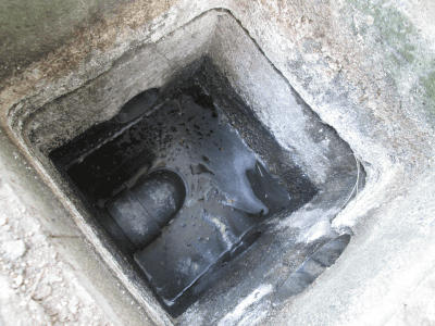
Let us begin by explaining how a sewage trough, which is part of catch basins, functions. Sewage troughs, also known as invert troughs, are installed at various locations around a residential water supply. They serve to store wastewater and separate it into suspended solids and sediment. Domestic wastewater from the home flows into the sewage catch basins through a drainpipe. Suspended solids that float in the water and sediment that settles to the bottom are then collected in the middle of the catch basins to prevent them from entering the sewer system. As a result, drainage only occurs when the water level reaches a certain point.

Drainage pipes connected to the sewerage system can consist of straight pipes or straight pipes with elbow joints. Sewage troughs require regular cleaning as they have limited self-cleaning capabilities. Particular attention should be given to troughs connected with elbow joints, as increased sedimentation can cause drainage loss.

Types of Catch Basins

In addition to sewage catch basins, various other types of catch basins exist.

Firstly, there are rainwater troughs.

Rainwater troughs are bucket-shaped cylindrical structures designed to store and collect rainwater. They are typically installed along house gutters. The number of units to be installed is determined by calculating the amount of runoff from the roof and the property. Municipalities often have specific regulations governing how rainwater should be managed. If it is not directed into an external gutter, it can be diverted to a storm drain or infiltrated into the ground for absorption. When using storm sewers, care must be taken during connections, as these systems incorporate separate pipes for sewage and rainwater to ensure proper treatment.

The next type is the public trough.

Catch basins are strategically placed to prevent blockages in sewage and rainwater pipes or to redirect drainage pipelines.

The public trough serves as the final collection point before connecting to the sewage system on residential and public street sides. Typically, public basins are installed by the sewer superintendent.

Lastly, mud pool basins and drop basins exist.

Mud pool basins share a similar structure to collection basins along public roads. They are positioned within stormwater pathways to allow debris, mud, and other contaminants to settle, preventing pipe obstructions.

A drop basin is a specialized basin installed to ensure proper slope for drainage. It is employed to adjust the drainage angle, as drainage can be impeded if it deviates from a certain gradient.

カテゴリー
category_usa

Ring Shim

What Is a Ring Shim?

A ring shim is a specialized shim designed to adjust position, level, and spacing between parts or between parts and equipment. Characterized by their ring shape and uniform thickness, ring shims facilitate the absorption of dimensional and accumulated tolerances during the assembly of multiple parts, enabling precise positional adjustments in the field.

Applications of Ring Shims

Ring shims find widespread use in machinery and equipment assembly, where precise spacing or positional adjustments between components are required. Their applications include:

1. Position Adjustment of Bearings and More

Inserted into the inner and outer rings of bearings, ring shims aid in securing and adjusting positions axially. They are crucial for setting bearing preload in angular and tapered roller bearings by aligning the inner and outer rings. Similarly, ring shims adjust the shaft positions of gears and pulleys, mirroring their application in bearings.

2. Position Adjustment with Screw and Bolt Holes

Ring shims enable positional adjustments at screw or bolt fastening surfaces without the need for specially shaped shims. By inserting ring shims into threaded holes, the fastening surfaces’ positions can be finely adjusted, also facilitating height adjustments for pins.

3. Position Adjustment on Flange Surfaces

Placed around the inner and outer circumference of flange surfaces, ring shims allow for positional adjustments without special shim shapes, avoiding fastening holes for seamless integration.

Principle of Ring Shims

Ring shims serve as precision components for fine-tuning spacing and positions, thanks to their uniform thickness and ring shape. They are available in a broad range of thicknesses, from tens of micrometers to several millimeters, and are made from materials like steel, stainless steel, copper, and brass.

Types of Ring Shims

Beyond the standard ring shape, ring shims come in several variations:

1. Notched Type

Notched (or split)-type ring shims feature a partial notch, allowing for easy insertion and removal during assembly without fully disassembling bolts or shafts. Caution is advised to prevent tilting by avoiding notch alignment when using multiple shims.

2. Laminated Type

Laminated ring shims consist of ultra-thin layers bonded together, enabling thickness adjustments by peeling off layers as needed.

Other Information on Ring Shims

Usage Considerations

When using ring shims, it’s essential to minimize the stack to avoid contamination or alteration of thickness. Ring shims are distinct from washers and spacers, which are used for more significant height adjustments. Often, ring shims are marked or color-coded for easy identification of thickness and to prevent loss or reflectivity issues during assembly.

カテゴリー
category_usa

Plastic Engineering Compound

What Is a Plastic Engineering Compound?

Plastic Engineering Compounds

Engineering plastics are a class of plastics known for their superior performance compared to conventional plastics. Many of them exhibit excellent strength and heat resistance, making them essential in various machinery applications. Additionally, they share the advantages of being lightweight and cost-effective while delivering high performance, making them promising alternatives to metals. Among plastic engineering compounds, those with exceptionally high performance are often referred to as super plastics, and ongoing research explores their applications in diverse products.

Applications of Plastic Engineering Compounds

Plastic engineering compounds come in various types, each tailored to specific properties, and find applications across a wide range of devices based on their intended use. Examples include automotive parts, electrical products, and small electronic components. Compounds with outstanding impact strength and durability are chosen for parts subjected to prolonged and heavy forces. Moreover, most plastic engineering compounds exhibit excellent heat resistance, making them suitable for use in heated equipment or high-temperature environments. Compounds with chemical resistance are occasionally used in laboratory equipment.

Principles of Plastic Engineering Compounds

Several types of engineering compounds are currently under development, and here are five of their main characteristics:

  • Polyacetal
    This material offers excellent fatigue resistance and boasts high abrasion and insulation properties. However, it can only be produced in an opaque form.
  • Polyamide
    This material is known for its exceptional strength and chemical resistance. However, it has a high affinity for water absorption, causing it to expand and lead to size discrepancies when exposed to moisture.
  • Polycarbonate
    With outstanding heat and cold resistance, this material can be used within a wide temperature range (-40°C to 120°C). However, its chemical resistance is relatively low, necessitating caution when used with certain chemicals.
  • Modified polyphenylene ether
    This material exhibits excellent electrical properties and minimal water absorption. However, it is incompatible with organic solvents as it dissolves in them.
  • Polybutylene terephthalate
    Resistant to friction and abrasion, this material offers excellent electrical insulation properties. Nevertheless, it is vulnerable to hydrolysis, and its heat resistance is somewhat limited.

Medical Plastic Engineering Compounds

Medical plastic engineering compounds must meet specific criteria, including excellent heat resistance, chemical resistance, corrosion resistance, and biocompatibility.

For example, polyphenylene sulfide resin (PPS), known for its exceptional heat resistance, chemical resistance, and mechanical properties, is employed in medical tubing.

Polyetheretherketone resin (PEEK) is recognized for its high biocompatibility, outstanding chemical resistance, mechanical properties, and is used in applications such as bone fixation aids, spinal implants, orthopedic implants, craniofacial implants, and artificial tooth roots. Polysulfone resin (PSU) exhibits excellent hydrolysis resistance, chemical resistance, and hygienic properties, making it suitable for dialysis membranes in artificial kidneys and medical devices.

Polyethersulfone resin (PES) offers excellent mechanical properties, chemical resistance, including resistance to hot water and chemicals, flame resistance, and moldability. It finds use in contact lens sterilization containers and syringe syringes.

Adhesion Technology for Plastic Engineering Compounds

Engineering plastics are extensively used across various fields, particularly in automotive parts where stringent quality and weight reduction requirements apply.

Automotive components utilize materials such as polybutylene terephthalate resin (PBT) and polyphenylene sulfide resin (PPS), known for their long-term stability in high-temperature environments.

One of the major challenges in applying engineering compounds to automotive parts is ensuring proper bonding between components.

Surface properties of plastic engineering compounds tend to be stable, which can sometimes result in insufficient adhesive strength. As a result, extensive research has been conducted to enhance adhesion.

For engineering plastics used in demanding environments, such as high temperatures in automotive parts, annealing (heat treatment) is generally applied to parts to ensure dimensional stability before bonding.

However, annealing treatment forms a fragile layer on the component’s surface, leading to reduced adhesion. Research has shown that removing this fragile layer can improve adhesion.

カテゴリー
category_usa

Position Switch

What Is a Position Switch?

A position switch is a contact-type sensor, also known as a touch switch or high-precision switch. It operates by activating when a movable pin at the end is pushed to a specific point by a sensing object. Known for their extremely high accuracy, position switches enable precise control and detection of an object’s position. They are crucial in applications requiring accuracy but must be installed correctly to ensure precise detection.

Position switches are similar to microswitches and limit switches but are distinct in their durability and accuracy, with some models capable of detecting positions in the micron range and enduring up to 3 million cycles.

Uses of Position Switches

  • Manufacturing Industry: Used in assembly and production lines for accurate position detection and control of parts and products. In machining, they detect tool positions for precise cutting and machining and control robot arm positions.
  • Medical: Used in medical equipment to detect specific positions or changes, such as in diagnostic imaging equipment and surgical support robots.
  • Printing Machines: Used in printing presses to accurately control paper position and feed, ensuring proper operation of the print head and ink supply.

Principle of Position Switches

Position switches detect position through physical contact and consist of an actuator, contacts, and a spring. The actuator changes the switch state when pushed, the contacts open and close the electrical circuit, and the spring returns the switch to its original state.

How to Select a Position Switch

  • Type of Actuator: Choose an actuator type based on the operating environment and application, such as pin plungers, top plungers, or bevel plungers.
  • Operation Indicator Light: Consider whether an indicator light is necessary for visual confirmation of the switch status.
  • Repetition Accuracy: Ensure the switch can repeatedly detect the same position with high accuracy, crucial for certain applications.
  • Force Required for Operation: Select a position switch that requires an appropriate amount of force for operation, matching the application’s requirements.
カテゴリー
category_usa

Measuring Light Curtain

What Is a Measuring Light Curtain?

Measuring Light Curtains

A measuring light curtain is a safety sensor that detects when a person or object enters the hazardous area of a machine or equipment.

They are sometimes also referred to as light grids. Light curtains are installed at entrances and exits of machinery without doors to provide time for the light to stop when it detects that the light beam has been interrupted. This happens at a distance where no person or object is in contact with the hazardous area.

Since the size of the smallest detectable object varies from device to device, it is crucial to select the appropriate one based on the size of the object to be blocked, the safety distance, and the installation site’s height. Measuring light curtains typically use LEDs that emit infrared rays with a wavelength of about 900 nm, as the specified light source falls in the 400 nm to 1,500 nm wavelength range.

Uses of Measuring Light Curtains

Measuring light curtains are commonly employed to enhance safety in manufacturing facilities with automated production processes, including metal processing, pharmaceuticals, food production, packaging, semiconductor manufacturing, transportation, and automotive industries.

When partitions or doors cannot be installed in hazardous operational areas, such as automated assembly machines, mounting machines, packaging equipment, printing machines, and line conveyor systems, they serve to monitor for the intrusion of workers’ hands, fingers, arms, legs, other body parts, and obstructions.

Principles of Measuring Light Curtains

Measuring light curtains consist of a floodlight and a receiver, installed as a set. The floodlight contains aligned projection elements, and the receiver also features aligned projection elements. They are positioned in parallel, allowing multiple parallel light beams emitted from the projector side to be received on the receiver side.

When the receiver side successfully receives all of the multiple beams emitted by the projector side, it is considered normal, and the machine or equipment’s operation is allowed. If any part of the light path is blocked due to an intrusion, such as a worker’s hand or leg, the system recognizes the situation as dangerous and halts the machine or equipment’s operation.

The light curtain also includes a muting function, which differentiates between a workpiece passing through the detection area and a human body entering the detection area. It also has a blanking function, enabling the disabling of a specific portion of the detection area.

How to Select Measuring Light Curtains

A wide variety of measuring light curtains are available from different manufacturers. To make the best selection, consider the following points:

1. Measuring Light Curtain Length

The length of the main body of measuring light curtains should be suitable for the actual production site where they will be used. If it is too short, it may fail to detect if any part of a worker’s body enters the hazardous area, potentially leading to accidents. Conversely, if it is too long, installation may become impractical.

2. Water and Oil Resistance

Production sites often involve dust and other particles. If these particles adhere to the projector and receiver surfaces of measuring light curtains, the light receiver may fail to detect the projector’s light properly, resulting in false danger alerts. Therefore, opting for water-resistant curtains simplifies maintenance.

3. Synchronization Method

Measuring light curtains rely on synchronized timing between the light emitted by the projector and the light received by the receiver to ensure safe monitoring. Two synchronization methods exist: wired synchronization, where the projector and receiver are connected by a synchronization wire, and optical synchronization, where they are connected optically by a synchronization wire.

Optical synchronization involves less wiring and is easier to manage, but generally, it is limited to a smaller number of light curtains to prevent false detection (interference) caused by light projectors from different measuring light curtains.

4. Ease of Optical Axis Alignment

Measuring light curtains require the receiver to capture all the multiple lights emitted by the floodlight. This necessitates adjusting the position and angle of the projector and receiver, known as optical axis alignment. Additionally, it is important to check whether the curtain provides clear indications of which part of the receiver receives specific amounts of light and whether it is resistant to torsion, among other factors.

カテゴリー
category_usa

Sanitary Piping

What Is Sanitary Piping?

Sanitary Piping

Sanitary piping, primarily used in the food industry and pharmaceutical plants, is designed for environments where cleanliness and hygiene are paramount.

All sanitary piping is constructed from stainless steel, specifically grades such as SUS304 or SUS316. The key distinction between sanitary and ordinary piping lies in the surface treatment. Sanitary pipes typically have a buffed outer surface and at least a bright annealed (BA) inner surface, while higher-grade options feature an electropolished (EP) inner surface to minimize liquid accumulation.

Uses of Sanitary Piping

In the food and pharmaceutical industries, where contamination from foreign matter or bacteria is unacceptable, sanitary piping is essential. Even minor liquid buildup in the food industry can lead to bacterial growth, potentially impacting the product and, in severe cases, causing significant public health concerns.

Similarly, in pharmaceutical manufacturing, any contamination by foreign substances or bacteria can have serious implications, given that these products are often used directly in the body.

Principles of Sanitary Piping

Most sanitary piping is made from either SUS304 or SUS316 stainless steel. This material choice ensures rust resistance and chemical resistance to agents like hot water and caustic soda used in Clean-in-Place (CIP) processes. The BA and EP finishes on these pipes prevent tiny fluid accumulations, a common source of bacterial growth, thereby significantly enhancing product safety.

Unlike sanitary piping, ordinary SUS piping often retains fine scratches and is not suitable for use in the food or pharmaceutical industries. While high-quality sanitary piping would be ideal for all applications, it is considerably more expensive than ordinary piping. Additionally, its effectiveness is fully realized only when used with dedicated joints, necessitating specialized knowledge in design and installation.

Sanitary Piping Standards

Sanitary piping, referred to as TBS, is specified in JIS G 3447. Nominal diameters are expressed in inches, ranging from 1S (O.D.=25.4 mm) to 6.5S (O.D.=165.2 mm), with a uniform wall thickness for each size (e.g., t=1.2 for 1S and 1.5S). Available in lengths of 4m or 6m, these pipes come with various surface finishes like pickling, internal buffing and polishing, with an option for electrolytic polishing on the inside.

Sanitary piping is made from austenitic stainless steel like SUS304, SUS304L, SUS316, or SUS316L, selected for its excellent corrosion resistance. This is particularly crucial in applications where chlorine ion concentration is high, as in certain food and pharmaceutical industries.

Sanitary Fittings

Sanitary fittings include “ISO Ferrule union fittings,” “ISO threaded union fittings,” and “flange fittings. Typical fittings are ISO Ferrule union fittings, which include elbows of various sizes (45°/90°/88.5° for flow gradient), cheese, crosses, reducers for connecting odd-shaped sizes, ferrule caps for closing ferrule ends, welding ferrules for pipes and tanks respectively, and clamps for joining two ferrules. There are a variety of joints, including two-piece, three-piece, hand-tightened, and bolted joints.

ISO threaded union fittings and flange union fittings are also available in almost similar types, allowing various piping systems to be assembled.

Gaskets for Sanitary Fittings

Gaskets for sanitary fittings include L-type gaskets for ISO threaded unions, Hercule gaskets for ISO Herule unions, and L-type gaskets for flange unions. Material choices include silicone, EPDM, FKM, Teflon, and Teflon-coated with EPDM core, selected based on the application. These gaskets are designed to not protrude inside the piping, ensuring unobstructed flow and no liquid pooling.

カテゴリー
category_usa

Cycloidal Reducer

What Is a Cycloidal Reducer?

A cycloidal reducer refers to a type of gear mechanism with a trochoidal curve (a smooth curve) that can efficiently reduce speed with minimal slippage. Compared to gears with rectangular teeth, cycloidal reducers are known for their characteristics of reducing wear, vibration, and extended service life. These reducers are commonly employed in devices that rely on rotational motion, such as motors and pistons.

Their structure typically consists of a large-diameter gear enclosing a smaller-diameter gear, enabling them to achieve high reduction ratios.

Applications of Cycloidal Reducers

Cycloidal reducers find applications in various industries, including industrial robotics, pumps, automotive drives, ship propulsion systems, aircraft propellers, and wind turbine propellers. They play a crucial role in converting rotational motion and torque produced by sources like engine pistons and electric drive motors into torque and speed levels suitable for other equipment. When selecting cycloidal reducers, factors such as reduction ratio, frictional losses, size, and ease of maintenance should be considered.

Principles of Cycloidal Reducers

Cycloidal reducers consist of two mounting shafts, two reduction gears, and bearings supporting the shafts and gears. The gears are designed in the shape of a trochoidal curve, which represents the locus of the outer point of a circle moving smoothly along the curve without slipping. This gear system operates with one gear rotating within another gear.

During operation, rotational motion is transmitted from the shaft with higher speed to the high-speed gear, often an internal gear, which, together with an eccentric bearing, moves along the inner circumference of the external low-speed gear. This motion results in a reduction in speed, with the output shaft delivering lower-speed, higher-torque rotation compared to the input torque.

Some cycloidal reducers incorporate holes in the gears, using external pins or similar mechanisms to reduce the load on the eccentric bearings.

Advantages of Cycloidal Reducers

Cycloidal reducers offer several advantages:

  1. High Reduction Ratio: They can achieve high reduction ratios, often up to 1/150, due to minimal differences in the number of teeth between gears.
  2. Compact Design: A single gear can provide a high reduction ratio, eliminating the need for multiple gears and enabling a slim design.
  3. Efficiency: Cycloidal reducers operate with rolling gears rather than sliding gears, resulting in minimal friction loss and high transmission efficiency.

Due to these features, they are commonly used as reduction gears in various applications.

Oil Change for Cycloidal Reducers

Cycloidal reducers use lubricating oil, and it is essential to maintain the proper oil level. Monitoring the oil level with an oil gauge is necessary because the oil volume can fluctuate during operation.

Using too much or too little oil can have adverse effects. Excessive oil may lead to motor-side oil infiltration, leaks, or abnormal temperature increases. Insufficient oil can result in inadequate lubrication of gears and bearings, leading to abnormal wear or temperature rises due to inadequate cooling.

Guidelines for oil replacement can be found in the technical documentation provided by each manufacturer. However, it is essential to periodically check and replenish the oil to maintain the correct level. Typically, the first oil change should be performed early in the equipment’s lifecycle, followed by regular replacements.

If the oil contains iron particles or other contaminants, it may indicate wear in the gears and bearings, necessitating inspection and maintenance. Changes in oil viscosity and other factors can also lead to malfunctions.

During routine inspections, early-stage abnormalities can be detected by comparing factors such as oil quantity, oil condition (presence of dirt, etc.), oil leaks in the surrounding area, temperature changes during rotation, and abnormal noises during operation with normal operation data. Therefore, keeping records of data (temperature, vibration, sound, etc.) during regular operation can be valuable for maintenance purposes.

カテゴリー
category_usa

Crossed Roller Table

What Is a Crossed Roller Table?

A crossed roller table is a precision linear motion table that features rollers with retainers placed in alternating tolerances between a high-precision V-shaped groove on the underside of the table and its base. This design allows for precise linear motion supported by multiple rollers.

Crossed roller tables are commonly used in office automation equipment and IC processing machines due to their exceptional rigidity in various directions and high-precision linear guidance capabilities.

There are also cross-roller rings and cross-roller bearings, which incorporate circular grooves instead of straight V-shaped grooves and enable rotational motion. These components provide the same characteristics as crossed roller tables and are used for supporting tables or shafts.

Applications of Crossed Roller Tables

Crossed roller tables find widespread use in applications requiring high precision and rigidity in linear motion. They are prominently featured in office automation equipment, various measuring instruments, IC manufacturing equipment such as printed circuit board drilling machines, and medical equipment.

Crossed roller bearings serve a broad range of purposes, including joints and swivel components in industrial robots, joints of robot suits for nursing care, swivel tables in machining centers, precision rotary tables, measuring instruments, and IC manufacturing equipment. Their applications are expanding into cutting-edge fields like aeronautics and space exploration.

Features of Crossed Roller Tables

Crossed roller tables incorporate V-shaped polished guide grooves on the underside of the table, with rollers positioned between the base and the guide grooves using retainers that alternately contact both sides of the V-shaped guide grooves. This arrangement enables precise linear motion, and the use of two parallel guide grooves supports loads in multiple directions, enhancing rigidity.

These tables feature highly accurate rollers, guide grooves, and base components, with adjustable gaps using screws to apply pressure. Supported on two intersecting surfaces, they maintain high rigidity even when subjected to loads in vertical and horizontal directions, as well as bending moments in various directions.

Furthermore, versions made of stainless steel for V-shaped grooves, bases, rollers, and retainers offer extended service life and corrosion resistance. They can easily provide high-precision linear guidance by simple bolt-on mounting.

Rotatable cross-roller rings are known for their high rotational accuracy, preventing roller skew and mutual friction. This results in stable rotational torque, making them suitable for various applications.

カテゴリー
category_usa

Dust Arrester

What Is a Dust Arrester?

A dust arrester is a device designed to remove not only dust particles but also algae, small fish, and similar debris from water, ensuring the provision of clean water. These devices are predominantly utilized in power plants and irrigation canals.

A dust arrester’s functionality extends beyond mere dust removal. It also conveys the extracted matter to a primary storage facility and separates water from it. Consequently, the system comprises multiple components, including screens, dust arresters, conveyors, storage units, and control equipment, each fulfilling a specific role.

Uses of Dust Arresters

Dust arresters play a crucial role in supplying dust-free water, particularly in thermal and nuclear power plants.

These power plants require substantial quantities of cooling water. Sea water, however, often contains various forms of debris like jellyfish, seaweed, and small fish, rendering it unsuitable for this purpose. Dust arresters, therefore, are installed at the water intakes of these plants to filter out such particles.

Principles of Dust Arresters

Dust arresters operate by employing a screen to trap dust and debris in the water. This trapped material is then collected by a dust collector, which is subsequently scooped up for removal. There are primarily two types of dust collectors: rake-type and net-type.

Rake-type dust collectors come in two variations: stationary and mobile. The stationary type is affixed to a single location, while the mobile type is mounted on a cart, allowing for movement. The mobile variety is more cost-effective but less efficient in movement, whereas the stationary type boasts a higher dust removal capacity.

Rakes in dust arresters are categorized into rotary and reciprocating types, based on their movement. In the rotary type, the rake moves upstream or downstream of the screen, lifting the trapped dust as it ascends. Conversely, the reciprocating type descends in front of the screen and rises along its surface, effectively collecting dust. Large-scale equipment typically employs wire rope-driven reciprocating rakes, while smaller equipment uses a chain rack mechanism.

Net-type dust collectors are available in dual-flow and straight-flow designs. The straight-flow model poses a risk of downstream dust spillage during cleaning, a problem that dual-flow models do not encounter.