カテゴリー
category_usa

Central Processing Unit (CPU) Cooler Fan

What Is a CPU Cooler?

A CPU cooler is a component that cools the Central Processing Unit (CPU) of a computer, typically found in personal computers.

During operation, the CPU generates heat, which can cause malfunctions due to thermal runaway if not adequately cooled. A CPU cooler, chosen based on the CPU’s power consumption, mitigates this risk.

There are two primary types of CPU coolers: air-cooled and water-cooled. Air-cooled variants are more common, while water-cooled coolers are often used in high-end gaming PCs and custom builds.

Uses of CPU Coolers

CPU coolers are essential for preventing thermal runaway, ensuring stable operation by managing the heat generated by the CPU. They are a standard feature in most desktop and laptop computers.

Available as standalone units for custom computer builds, CPU coolers vary in type, catering to different CPU power levels, manufacturers, and form factors.

Principles of CPU Coolers

CPU coolers facilitate heat exchange using air or water as mediums.

1. Air-Cooled Type

The air-cooled variant transfers CPU-generated heat to a heat sink made of thermally conductive materials like aluminum or copper. This heat is then dissipated through a fan or natural convection.

2. Water-Cooled Type

Water-cooled coolers transfer heat to water, which carries it to a radiator for dissipation.

Components of CPU Coolers

1. Air-Cooled Type

An air-cooled CPU cooler comprises a base plate, heat pipes, a heat sink, and sometimes an electric fan. Copper or aluminum alloys are used for their thermal conductivity, and thermal grease improves heat transfer from the CPU to the base plate.

Electric fans generate airflow to cool the heat sink and other motherboard components. The size of the heat sink is crucial for dissipation efficiency but is limited by the case’s internal space.

2. Water-Cooled Type

Water-cooled coolers use heat pipes and cooling hoses for heat transfer, with a radiator serving as the dissipating component. Radiators can often be installed externally, offering improved cooling capacity.

However, these systems carry a risk of coolant leakage.

Selecting a CPU Cooler

Consider the following when choosing a CPU Cooler:

1. Supported CPU Sockets

Ensure compatibility with your CPU socket.

2. Cooling Performance

Choose a cooler that matches the CPU’s heat output. Note that high-performance CPUs require more effective cooling to prevent performance throttling.

3. Quietness

For quieter operation, look for coolers with a noise level around 30db.

4. Size

Verify that the cooler fits within your system without obstructing other components like memory or expansion boards.

カテゴリー
category_usa

Thread Cutting Tool

What Is a Thread-Cutting Tool?

A thread-cutting tool is a machining tool capable of processing female threads through helical interpolation using a machining center or an NC milling machine. The processing machine must, therefore, be capable of helical interpolation.

Unlike ordinary taps, milling in machining offers low cutting resistance and a reduced risk of breakage. Even in the unlikely event of breakage, the tool can be easily removed.

Various thread diameters can be processed by altering the program, provided the thread pitch remains the same.

Uses of Thread-Cutting Tools

Thread-cutting tools are particularly useful for high-hardness steel, which is challenging to process with standard taps.

Certain types can perform both pre-hole drilling and thread cutting with a single tool.

These tools provide ample chip evacuation space and can process threaded holes with high precision and surface roughness due to the milling process.

While ordinary taps require high torque, leading to potential chipping during cutting, thread-cutting tools achieve cutting with lower torque, ensuring stable operation.

Principles of Thread-Cutting Tools

Thread-cutting tools can machine threads of varying nominal diameters with a single tool. This capability applies to both right- and left-hand threads, as long as they share the same pitch.

Since machining dimensions are adjustable via programming, there is no need for different tools for each accuracy level. This simplifies tool management and reduces tooling costs.

The machining process is akin to the side machining of an end mill, allowing large-diameter threads to be machined with low-torque machines compared to regular tapping.

The milling process yields finer chips and does not produce long chips like in tapping. This ensures stable machining without chip-related issues.

Threads can be machined with only one incomplete peak. The milling chuck‘s grip on the tool ensures extremely high depth-direction accuracy. This tool is especially suitable for machining stop holes with limited space.

When machining tapered pipe threads, thread-cutting tools do not leave a stop mark, unlike normal tapping processes. This results in improved roundness and enables the machining of threads with excellent tightness resistance.
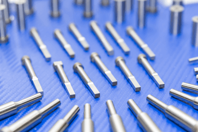
カテゴリー
category_usa

Carbide Punch

What Is a Carbide Punch?

Carbide Punches

A carbide punch is a punch made of cemented carbide.

It is also called cemented carbide. Cemented carbide is a metal alloy made by adding tungsten carbide (WC) and titanium carbide (TiC), using cobalt (Co) powder as a binder, and sintering (pressing and solidifying the material at a temperature of 1300° to 1500° by heating it near its melting point) in a pressurized mold.

A carbide punch is a challenging and heat-resistant punch used for wear resistance. Regular punch material (equivalent to SKD11) becomes hard to cut when the cutting edge of the punch begins to sag due to frictional heat (around 1330°).

Uses of Carbide Punches

Carbide punches are a wear-resistant measure because they are made of carbide metal.

They are mainly used for precision dies and as punches for press dies. It is possible to maintain stable dimensions using carbide punches, which have little dimensional fluctuation due to wear.

Carbide punches have excellent wear resistance and are robust against compressive stress but weak against tensile stress, so the punch holding section must be reinforced when used.

Principle of Carbide Punches

Gold has the property of elongation when struck at room temperature.

However, iron does not elongate when struck at room temperature.

By adding heat to iron (around 1330°), it begins to elongate when struck.

In other words, gold has the same property at room temperature, and iron has the same property when heated to 1330°.

This is the difference between gold and iron.

The wear mechanism of the metal is that the part of the metal that comes in contact with the iron with the binder will be at around 1330° and

The metal becomes soft and wears by having the same properties as gold.

This is the wear mechanism.

If this is the case, to make a metal resistant to wear, it should not become soft even at a temperature of around 1330°.

This is called SKH51 (high-speed steel).

This is SKH51 (high-speed steel), a cemented carbide.

HSS is often used as a heat-resistant wear-resistant material because it begins to wear when heated to around 1550°.

Therefore, it is often used as a heat-resistant wear-resistant material.

Some cemented carbide materials do not wear out at temperatures above 2000° and even at 4000°.

You can understand how heat-resistant and hard they are.

However, it is not all merit.

Because of its hardness, it is less pliant and easily broken.

It is vital in compression but weak in tension and lateral force.

カテゴリー
category_usa

Involute Spline

What Is an Involute Spline?

An involute spline is an element whose tooth profile is formed using an involute curve. It is more precise than elements using general keyways and can transmit greater torque.

Spline is a fastening element that transmits power by meshing structures with external and internal teeth cut into each other. The fundamental principle is similar to that of gears (spur gears), where external teeth mesh together.

In Japan, an involute spline is standardized by JIS. When considering the assembly of an involute spline into a mechanical device, it is necessary to confirm that it conforms to the JIS standard.

Uses for Involute Splines

Compared to other splines like square splines and serrations, involute splines are easier and more precise to manufacture, making them widely used in mechanical devices.

For example, they are used in gearboxes for automobiles and motorcycles, where gears slide along the shaft to change speeds.

On the other hand, machining involute splines require a tooth height of a certain height, so it is not suitable for thin shafts or thin-walled shafts. In such cases, using a serrated type will enable stable rotation.

Principles of Involute Splines

The characteristic tooth profile of an involute spline is formed by drawing a specific curve known as an “involute curve.”

Wrap a thread around the cylinders circumference and attach a pencil to the end of the thread. Unwind the thread from its taut state and draw the trajectory of the thread with the pencil. The curve created by repeating this process is the involute curve.

When two tooth profiles made in this way are meshed and rotated, the contact points of both tooth profiles move smoothly on the same curve. Because of these characteristics, the involute curve can be considered suitable for tooth profile curves.

Easy to manufacture and ensuring accuracy, involute splines are more versatile than conventional square splines. Since each spline type has its characteristics, selecting the appropriate type for each application is necessary.

カテゴリー
category_usa

Retaining Ring

What Is a Retaining Ring?

A retaining ring, also known as a snap ring, circlip, or retaining ring, is a metal component used to secure a shaft and a shaft-through-hole component in position.

It is designed to fit into a machined groove on a shaft or hole and holds the attached part securely in place. The portion of the retaining ring that protrudes from the groove makes contact with the mating part, ensuring it stays fixed.

Uses of Retaining Rings

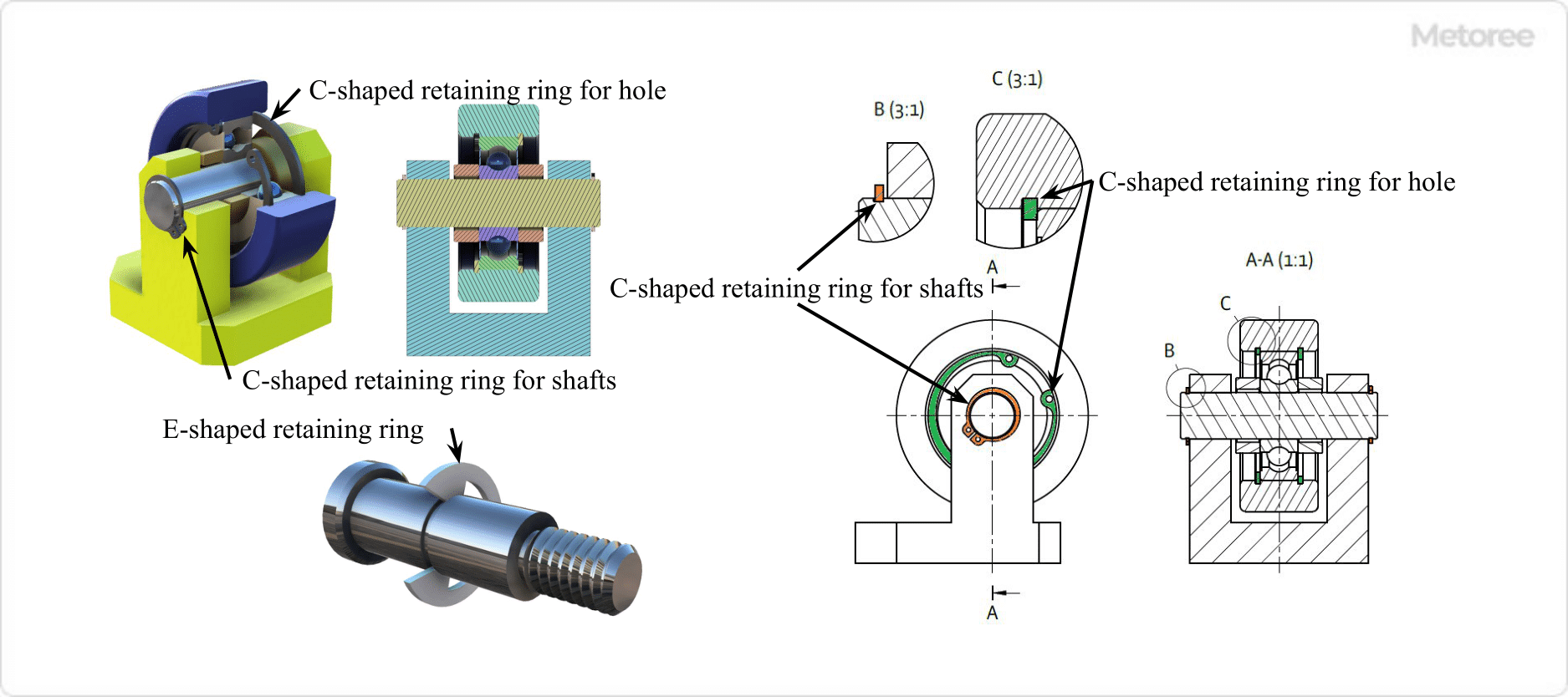
Figure 1. Example of retaining ring use

Figure 1. Example of retaining ring use

Retaining rings are commonly used in machinery to fasten parts like bearings or gears to shafts. They are available in both internal and external varieties for different applications. The selection of the ring’s shape and type depends on the fastening method and the restraining force required. Proper groove dimensions, according to JIS standards or manufacturer specifications, are necessary for installation.

Principle of Retaining Rings

Retaining rings are installed in a groove machined on the shaft or hole. The ring secures adjacent parts by fitting snugly into the groove, with its plate-width portion holding the part in place. See Figure 1 for a visual representation.

The groove dimensions are designed to accommodate the ring’s size. Special tools are often used to fit the ring into the groove properly. Once installed, the ring presses against the groove’s bottom to stay secure.

Types of Retaining Rings

1. Classification by Installation Direction

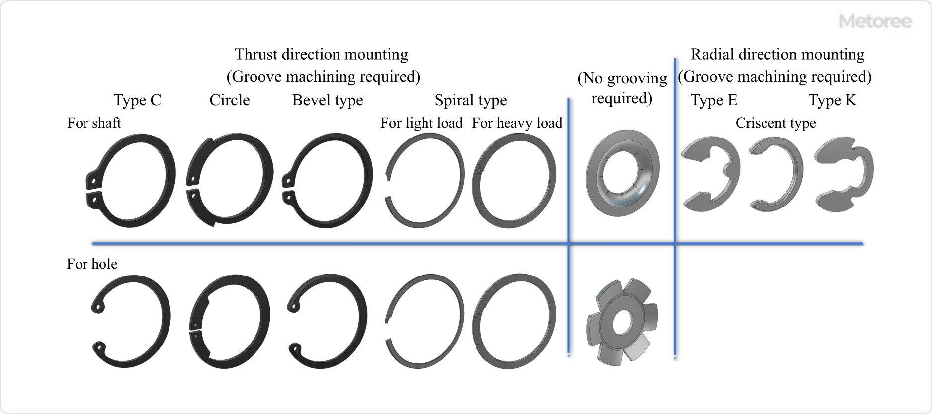
Figure 2. Mounting orientation of the retaining ring

Figure 2. Mounting orientation of the retaining ring

Retaining rings are categorized based on their installation direction, with specific types for thrust direction mounting and radial mounting, each requiring groove machining.

2. Classification by Shape

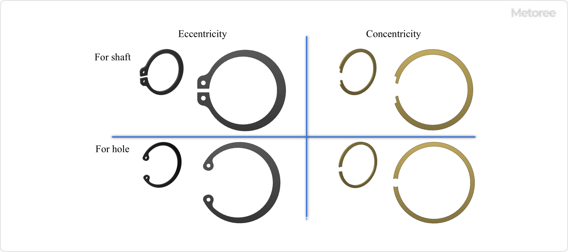
Figure 3. Shape of the retaining ring

Figure 3. Shape of the retaining ring

Retaining rings also vary in shape, including eccentric and concentric types, each with distinct characteristics and applications.

Other Information About Retaining Rings

1. Material and Surface Treatment of Retaining Rings

Retaining rings are commonly made from carbon steel, hard steel wire rods, or stainless steel strips. Surface treatments like phosphate coating or hexavalent chromium coating are applied for enhanced durability and corrosion resistance.

2. Retaining Ring Standards

  • JIS B 2804 Retaining rings
  • ANSI/ASME B18.27 Tapered and Reduced Cross-Section Retaining Rings (Inch Series)
  • ANSI/ASME B27.7 General purpose tapered and reduced cross-section retaining rings, Metric

3. Tools for Retaining Rings

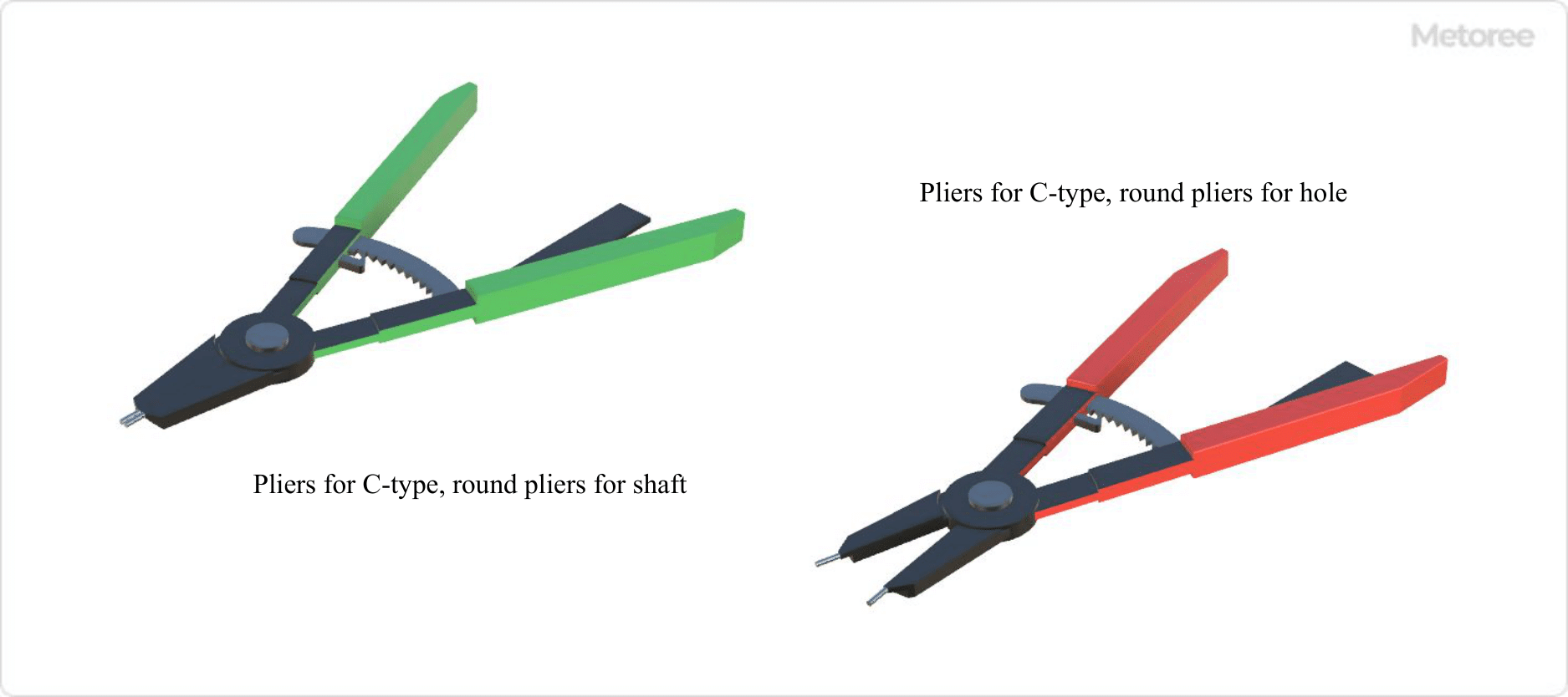
Figure 4. Pliers for retaining ring

Figure 4. Pliers for retaining ring

Special pliers are used for installing and removing certain types of retaining rings, such as C- and round-shaped rings. Spiral rings can be installed and removed without special tools.

カテゴリー
category_usa

Marking Laser

What Is a Marking Laser?

Marking Lasers

A marking laser is a device that uses a laser beam to mark lines. It can accurately mark vertical and horizontal lines. This marking process is essential in construction sites to accurately install piping and various conductors. A laser beam simplifies finding the correct placement. It also enables checking that windows and floor surfaces are level. Sometimes a measuring tripod is used to hold it in place, and sometimes a detection receiver is used if the laser is difficult to see.

Uses of Marking Lasers

Marking lasers are mainly used on construction sites. They are used for marking out the correct location of piping and other work. In the past, markings were made on walls and columns using ink and chalk, but vertical and horizontal lines can be easily checked with a laser. This makes it possible to install piping in the exact location as shown on the drawings. Furthermore, it simplifies checking vertical and horizontal lines in large buildings, ensuring that columns, windows, floors, etc., are not distorted.

Principles of Marking Lasers

There are two main types of marking lasers, differentiated by their methods of generating vertical and horizontal lines. Here we introduce the principles and features of the two types.

  • Gimbal type
  • This method uses a pendulum-like mechanism called a gimbal. A pendulum is attached to the mechanism that emits the laser, which always points vertically downward due to gravity. The laser is emitted according to the vertical direction of the pendulum, and a horizontal laser is emitted perpendicular to this light. The simple structure of the pendulum makes it a low-cost marker. However, with the pendulum swings, it is impossible to emit an accurate laser beam while moving the pendulum. Therefore, it is unsuitable for use in high-rise areas of buildings, where there is a risk of horizontal swaying from wind or other factors.
  • Electronic leveling type
  • This method calculates the horizontal displacement of bubbles in a liquid. Instead of a pendulum, a liquid containing air bubbles is attached. The level is checked by utilizing the change in the position of the bubbles as the pendulum is tilted. Although the electronic leveling method is not easily broken and is suitable for construction sites, temperature and air pressure can cause the bubbles to change, resulting in errors.


カテゴリー
category_usa

Belt Conveyor

What Is a Belt Conveyor?

Belt Conveyors

A belt conveyor is a mechanical system that transports materials using a continuous belt.

It is designed for the efficient and continuous transportation of various types and sizes of goods. Belt conveyors are highly effective for moving large volumes of items quickly and continuously, making them suitable for a broad range of industries and applications. They can also navigate different elevations and angles, accommodating various shapes and sizes of objects.

Regular maintenance of belt conveyors is essential. This includes inspecting belt tension and wear, as well as ensuring the power unit is functioning correctly. Prompt repair or replacement is necessary if the belt is damaged.

Uses of Belt Conveyors

Belt conveyors have diverse applications across various fields:

1. Manufacturing Industry

In the automotive industry, belt conveyors are integral to assembly lines, transporting engine parts, body components, and interiors. They are also used in the assembly and testing lines of electronic equipment, efficiently moving substrates, components, and finished products.

2. Logistics

Belt conveyors are crucial in warehousing for transporting and sorting goods, handling goods during receiving and shipping, and moving products to storage locations. They are also employed in packaging processes.

3. Food Manufacturing and Processing

The food manufacturing industry relies on belt conveyors due to their environmental resistance and ease of cleaning and maintenance, ensuring food safety and cleanliness.

Principle of Belt Conveyors

Belt conveyors operate on the principle of using a durable conveyor belt supported by rollers or pulleys, driven by a power unit like a motor or engine. The drive unit is typically situated at one end of the belt and is selected based on the conveyor length and load.

Tensioning devices maintain proper belt tension for optimal operation and stability. Belt tension is adjusted according to the type of belt and the load being transported.

How to Select a Belt Conveyor

The selection of a belt conveyor involves considering several key factors:

1. The Goods to Be Conveyed

The type and characteristics of the material to be transported are crucial. Larger, heavier items require a stronger drive and a more robust belt.

2. Distance and Speed

The required transportation distance and speed influence the design of the drive and belt. Control systems and speed regulators may be needed for long distances or high speeds.

3. Environmental Requirements

The operating environment impacts the choice of belt materials and protective measures. Considerations include temperature, humidity, chemical exposure, and the need for dust and waterproofing, which may necessitate specific seals and covers.

カテゴリー
category_usa

Volatile Corrosion Inhibitor (VCI)

What Is a Volatile Corrosion Inhibitor (VCI)?

A volatile corrosion inhibitor (VCI) is a chemical compound used to prevent rust formation on metal surfaces.

Also known as vapor-phase corrosion inhibitor (VRI), VCI works by vaporizing at room temperature. The vaporized inhibitor then adsorbs or reacts with the metal surface, effectively preventing rust. Some VCIs function by creating an atmosphere around the metal that inhibits rust, rather than directly interacting with it. These inhibitors are typically available as liquids or sprays and are easy to apply without requiring special equipment.

However, it’s important to note that some VCIs might contain hazardous substances. Users should review safety data sheets and follow safe handling practices, including proper ventilation and the use of personal protective equipment.

Uses of Volatile Corrosion Inhibitors (VCI)

VCIs are used in various applications to prevent rust on metal products, such as:

1. Automobiles

In the automotive industry, VCIs protect parts from environmental elements like road salt and moisture. They are used in manufacturing and maintenance to prevent rust, particularly in critical components like engines.

2. Warehousing

VCIs are employed in warehouses to prevent rust during long-term storage of metal products, especially in humid or variable environmental conditions.

3. Metal Processing

During metal processing and in operations like welding and painting, VCIs protect exposed metal surfaces from rust.

4. Outdoor Equipment

Outdoor equipment such as generators and air conditioning units are treated with VCIs to prevent rusting due to exposure to the elements.

Principle of Volatile Corrosion Inhibitor (VCI)

VCIs function by forming a thin protective film on metal surfaces, which blocks the elements that cause oxidation. These inhibitors are often in liquid or solid form and volatilize when applied to metal. The resulting protective film prevents the entry of materials that promote oxidation reactions.

Some VCIs create an oily film to cover the metal and inhibit oxidation, while others induce a chemical reaction on the surface to form a protective layer. This layer shields the metal from oxidation and corrosion. The durability of the protective effect varies, but proper selection and application can significantly enhance metal longevity and prevent rust formation.

How to Select a Volatile Corrosion Inhibitor (VCI)

Selecting a VCI involves considering the operating environment, the type of metal, and cost factors.

1. Operating Environment

The effectiveness of a VCI can vary with the use environment. Environments with high humidity or acidic gases may require stronger inhibitors. Assess the climatic and chemical conditions of the usage location and refer to product specifications and recommendations.

2. Metal Type

Different VCIs are formulated for specific types of metals. Confirm the metal type and select a compatible inhibitor.

3. Product Reliability

Consider product ratings and manufacturer reputation when choosing a VCI. Research product reviews and opt for products from reliable manufacturers.

カテゴリー
category_usa

Limit Gauge

What Is a Limit Gauge?

A limit gauge is an inspection tool designed for quick verification of a product’s dimensional conformity. It uses a pair of gauges representing the upper and lower acceptable limits of a product’s dimension. By testing whether a product can or cannot pass through these gauges, its acceptability is determined, making the process efficient for items like screws where dimensional accuracy is crucial.

Applications of Limit Gauges

Limit gauges are essential in mass production for process control, notably in manufacturing screws, but also applicable to various components to control thickness, height, width, and hole sizes. They ensure quality control with minimal measurement variation, suitable for use after thread forming, surface treatments, and during both shipment and acceptance inspections.

Principle of Limit Gauges

The principle relies on the ability of a product to pass through the ‘go’ gauge (street-side gauge) without passing through the ‘no-go’ gauge (stop-side gauge). This method ensures the product dimensions are within specified tolerances, verifying that dimensions do not exceed the maximum limit and are not below the minimum limit.

Types of Limit Gauges for Screws

Screw limit gauges come in various types, each designed for specific applications:

1. Ring Gauge for Screws

Used for inspecting male threads, ring gauges have a threaded hole that the screw must match to pass inspection. The acceptance criteria can include torque considerations, although there are no specific ISO regulations for torque during ring gauge inspection.

2. Plug Gauges for Screws

Plug gauges inspect female threads, similar in use to ring gauges, to ensure the thread fits appropriately.

3. Wear Inspection Gauges

These are used to check the wear on ‘go’ gauges to ensure they remain within acceptable tolerance ranges. Regular checks prevent false acceptances due to gauge wear.

Limit gauges for screws are detailed by standards, including ISO, with considerations for surface treatments like plating affecting screw dimensions. Agreements on gauge handling and acceptance criteria are essential in business transactions to ensure consistency and reliability in quality control processes.

カテゴリー
category_usa

Sealing Machinery

What Is Sealing Machinery?

Sealing machinery, also known as a carton sealer, is a semi-automatic or automatic machine used in factories and warehouses for taping corrugated boxes. The introduction of such machinery streamlines the taping process in packaging operations, enhancing efficiency while reducing labor and workspace requirements.

While basic models perform only tape stretching, more advanced machines, designed for integration into production lines, can simultaneously fold the flaps of corrugated boxes.

Uses of Sealing Machinery

Sealing machinery is extensively utilized for assembling and taping cartons in production plants and e-commerce shipping warehouses. While primarily used for corrugated cardboard, machines have been developed for various materials, including styrofoam, cans, and envelopes. These machines offer unique functions, such as applying glue and tape to sides and folding documents. The adoption of sealing machinery not only reduces manpower but also improves the packaging appearance and prevents accidents due to inadequate packaging.

Principles of Sealing Machinery

In sealing machinery for corrugated boxes, the system typically comprises a conveyor belt for transport, a folding flap section, and a tape unit. The process involves placing the carton on the conveyor belt, automatically folding the flaps when the carton reaches the right position, and then taping the top surface. Random-type machines, which can handle various box sizes, adjust their moving parts using air cylinders or similar devices. Electricity powers most sealing machinery, though some, like the random type, require an air supply for internal automatic adjustments.