What Is a Photomultiplier Tube?
A Photomultiplier Tube (PMT) is one of the most sensitive optical sensors capable of converting light (photons) into electricity.
It consists of a glass tube in a vacuum with an incident window, a photocathode, a dynode, and other components. The principle is based on the external photoelectric effect, a phenomenon in which electrons are emitted from the surface of a metal when light is irradiated on it in a vacuum.
Since even a single photon can be converted into a large electrical signal at high speed (10-9 seconds), photomultiplier tubes are used in electron microscopes, environmental analysis equipment, medical equipment, spectrophotometers, and spectral analysis equipment as photodetectors.
Applications of Photomultiplier Tubes
Photomultiplier Tubes are used as secondary electron detectors in electron microscopes and in photoanalytical instruments such as UV-visible spectrophotometers and emission spectrometers. They are also used in dust counters to measure particles in the air, in laser radar (LiDAR) to detect light scattered by suspended particles in the air, and in medical devices such as positron emission tomography (PET) and computed tomography (CT) used for cancer screening.
LiDAR provides a means of detecting the position and movement of objects around a vehicle and is also expected to be a key technology for fully automated driving. The Super-Kamiokande, the world’s most advanced facility for neutrino research, uses 13,000 20-inch diameter Photomultiplier Tubes to capture the Cherenkov light (light produced when electrons exceed the speed of light in water) generated in a 50,000 ton water tank.
Photomultiplier Tubes are extremely sensitive and are capable of converting faint light into a sufficient amount of electrical signals. On the other hand, they also have disadvantages, such as requiring high voltage for use and being prone to picking up noise caused by thermal electrons. Therefore, the power supply for Photomultiplier Tubes must have extremely low noise and high stability.
Photomultiplier Tube Principle
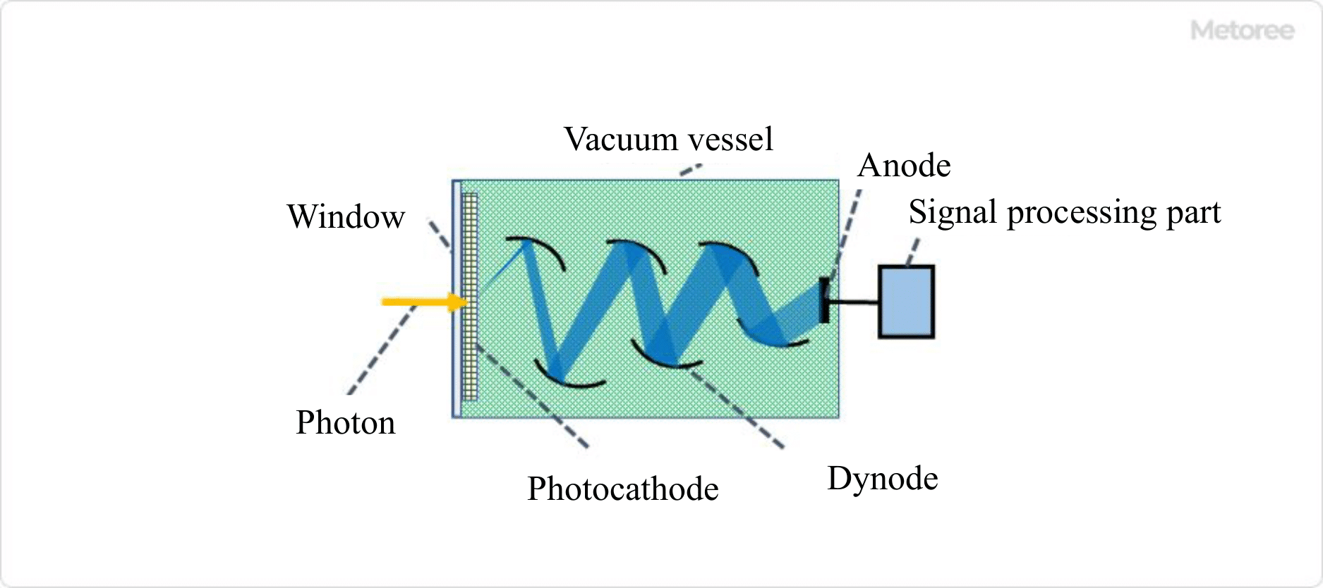
Figure 1. Basic structure of photomultiplier tubes
Photomultiplier Tubes are optical sensors that can detect light from a single photon and convert it into an electrical signal. Figure 1 shows the overall structure of a Photomultiplier Tube.
The glass tube in a vacuum state contains a window through which light enters, a photocathode that converts photons into electrons through the external photoelectric effect (the effect of electrons being emitted into a vacuum), a focusing electrode that collects the photoelectrons, a dynode with about 10 stages that multiplies secondary electrons, and an anode that generates an electronic signal. A DC voltage of about 1,000 V is applied to the entire area from the photocathode to the anode.
1. Window Material
Borosilicate glass, quartz glass, UV-transmitting glass, MgF2 crystal, etc. are used as window materials, depending on the wavelength region of the light, mainly on the short wavelength side.
2. Photocathode
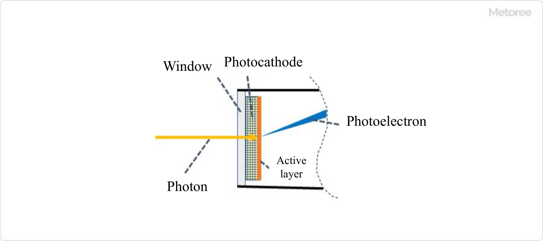
Figure 2. Photocathode and external photoelectric effect (Image)
The photocathode forms a quantum efficient (photoelectron generation efficiency) active layer on the surface in contact with the high vacuum. In the visible region, bialkali metal photocathodes, multi-alkali metal photocathodes of three or more types with sensitivity up to the infrared region, alkali halide photocathodes for UV detection, and photocathodes using III-V compound semiconductors with high sensitivity in the UV to near infrared region have been developed.
3. Die Node
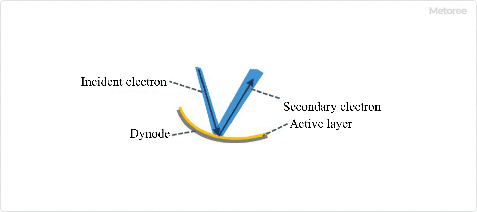
Figure 3. Structure and function of dynode (image)
Photoelectrons are accelerated by a focusing electrode and collected in a dynode. The dynode forms an active layer that increases the secondary electron emission ratio on a substrate metal such as nickel or stainless steel. Alkali metal-antimony (e.g., SbCs), beryllium oxide, and magnesium oxide are typically deposited on the layers.
When electrons strike the dynode, a large number of secondary electrons are emitted. The emitted secondary electrons collide with the next dynode, where more secondary electrons are emitted. This process is repeated until the number of electrons increases more than one million times, and is detected as a sufficient amount of electrical signal.
Other Information on Photomultiplier Tubes
Structure of Secondary Electron Multiplier
Various structures have been devised for the secondary electron multiplier, such as circular cage type, line focus type, box-and-grid type, fine mesh type, and metal channel type, depending on the arrangement and shape of the dynodes and other components.
For each structure, the optimum electrode design is made by electron orbital analysis. Electrons travel in a high vacuum, enabling fast time characteristic acquisition. The high sensitivity and fast response characteristics that count light as a grain are the reasons why PMTs are used at the forefront of the industry.