カテゴリー
category_usa

Transmitters

What Is a Transmitter?
Transmitters

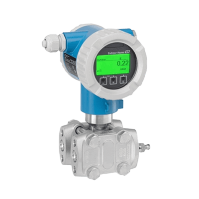
A transmitter is a device that transmits information measured by a sensor or other device to a different machine. It typically conveys pressure-related data like pressure, differential pressure, and pressure fluctuation. Transmission methods include pneumatic signals (using air pressure), electrical signals (using electrical signals and transmission lines), and optical signals (using optical fiber cables).

Uses of Transmitters

Transmitters are used in various facilities like plants, water treatment plants, and wastewater treatment plants. They are connected to pipes and ducts to measure and transmit fluid-related data such as pressure, liquid level, flow rate, and temperature to external devices. Selection criteria for transmitters include measurement range, accuracy, and transmission method. Some models also function as switches or controllers for other devices.

Principle of Transmitter

A transmitter consists of a sensor section for measurement, a processing section for signal conversion, and a transmission section for signal dissemination. It processes data such as pressure, flow rate, and temperature from sensors such as diaphragms, thermopiles, and transducers, converting it into electrical signals for transmission.

1. Processing Section

This section converts sensor data into electrical signals. Some Transmitters have built-in processors that generate control signals based on sensor data and send them to the transmission section.

2. Transmission Section

Here, information is transmitted via air pressure, electrical, or optical signals. Pneumatic signals are low-noise but slower, while electric or optical signals offer high-speed transmission but may be susceptible to noise in vibrating environments.

Types of Transmitters

Transmitters are classified based on their transmission methods:

1. Electrical Signal Type

This type transmits signals as electric current or voltage. It’s fast and suitable for long-distance transmission and easily integrates with control equipment or recorders.

2. Pneumatic Signal Type

Pneumatic signals use compressed air pressure for transmission. They are explosion-proof and resistant to electromagnetic noise but are not ideal for long distances and require clean, dry air.

3. Optical Signal Format

Optical signals use light flashes, usually transmitted through semiconductor lasers and optical fibers. Digital data is converted into optical blinks and sent through fibers, then converted back into electrical signals at the receiver. This format is ideal for long-distance, high-speed transmission in large plant instrumentation.
カテゴリー
category_usa

Zinc Die Casting

What Is Zinc Die Casting?

Zinc die casting is a process or product created using a method where high-temperature molten zinc is poured into a precision mold at high pressure and speed, forming a metal shape instantly. It is known for its extremely high dimensional accuracy and strength, as well as the flexibility it offers in producing a wide range of shapes. Due to these excellent characteristics, zinc die castings are used for a broad spectrum of products, ranging from daily necessities to industrial items.

Applications of Zinc Die Casting

Zinc die casting is utilized in various applications:

1. Architectural Hardware

It is used in architectural hardware for interior furnishings, including door knobs in residential spaces, made using zinc die casting. This technique allows for smooth surfaces that can be plated with metals like gold, silver, copper, chrome, nickel, or painted, offering diverse finishes.

2. Toys and Industrial Parts

Metal toys known as “superalloys” from the 1970s, characterized by their detailed shapes and substantial weight, are products of zinc die casting. In industry, it’s used for complex mechanical components such as motor shaft parts, gears, and transmission parts for vehicles and medical equipment, leveraging zinc‘s low melting point and precision.

Properties of Zinc Die Casting

Zinc, compared to aluminum alloys used in die casting, is stronger and allows for longer mold use, leading to significant production cost reductions. Additionally, its high electrical conductivity minimizes energy loss in mechanical and electrical parts, and its lower melting point eases the joining and processing of parts.

Characteristics of Zinc Die Casting

1. Suitability for Surface Treatment

Zinc die casting products, characterized by their smooth surface, are conducive to various finishing processes like plating or painting.

2. High Dimensional Accuracy

Offering higher precision than methods like plastic injection molding or gravity casting, zinc die casting is particularly advantageous for automotive parts and other precision-required applications.

3. Thin-Walled and Lightweight

The low melting point of zinc facilitates the production of thin-walled, lightweight products, making it an excellent choice for intricate designs.

4. High Mass Productivity

Zinc die casting is especially suitable for mass production, with molds lasting for a significantly higher number of uses compared to aluminum die casting.

Types of Zinc Die Casting

Two primary zinc alloys used in zinc die casting are ZDC1 and ZDC2, differing mainly in their copper content. ZDC1, with higher copper content, is chosen for its superior mechanical properties and corrosion resistance. In contrast, ZDC2 is preferred for interior furnishings and fittings requiring aesthetic finishes.

カテゴリー
category_usa

Dry-Type Transformer

What Is a Dry Type-Transformer?

Dry-type transformers are transformers that do not use insulating oil for cooling. Instead, they rely on air circulation around resin-coated coils for heat dissipation. This design offers several advantages, such as eliminating the risk of oil leaks and reducing environmental impact. However, they may not cool as effectively as oil-filled transformers and could require additional cooling equipment for larger capacities. Typically, dry-type transformers are more expensive than their oil-cooled counterparts.

Uses of Dry-Type Transformers

Dry-type transformers find applications in various settings:

1. Industrial Facilities and Factories

In industrial environments, they provide low-voltage power transmission to various equipment, offering safety advantages when installed indoors.

2. Commercial Facilities

They are widely used in shopping malls and other commercial buildings for powering lights, HVAC systems, elevators, etc., due to their low ignition risk.

3. Railroads

In railroad vehicles and systems, especially in enclosed spaces like subways, dry-type transformers offer enhanced safety and space-saving benefits.

Principle of Dry-Type Transformer

Dry-type transformers operate on the principle of electromagnetic induction, using two windings on an iron core to transform voltage. The heat generated during this process is dissipated via air cooling, contrasting with oil-filled transformers that use oil and cooling fins for heat dissipation.

Selecting a Dry-Type Transformer

Considerations for choosing a dry-type transformer include required capacity, voltage, and operating environment:

1. Required Capacity

Select a capacity that can handle average power usage efficiently, typically around 60% of the transformer’s capacity, while accommodating maximum power and inrush currents.

2. Voltage

Choose appropriate high and low-voltage sides, taking into account the specific requirements of the location and the load.

3. Operating Environment

Consider the installation location and environmental factors like humidity, temperature, and vibration to ensure the transformer’s suitability and durability.

Comparing Dry-Type and Molded Transformers

Dry-type transformers differ from molded transformers in cooling methods and protection performance. While dry-type transformers use varnish for winding protection and require external protection against physical damage and moisture, molded transformers encapsulate windings in insulating materials like epoxy resin for cooling and protection. This difference affects the manufacturing costs and applications of each transformer type.

カテゴリー
category_usa

Round Belts

What Is a Round Belt?

A round belt is a belt with a circular cross-section used in combination with pulleys to transmit rotational power through friction, similar to flat belts and V-belts.

  • Most round belts are made of polyurethane and are used to transmit the driving force of motors in processing machines and conveyors.

They are also used for driving belts in three-dimensional layouts (e.g., where each axis is in a twisting position) because there are no restrictions on the surface to which frictional force is transmitted, and no matter which direction the belt contacts the pulleys, it can be driven.

Uses of Round Belts

Compared to other belts such as V-belts and timing belts, round belts can be used to construct a power transmission system at a lower cost due to their simple cross-sectional shape. Also, they do not require a tension adjustment mechanism because of the belt’s elasticity.

Therefore, round belts are used in cost-saving equipment, when the assembly accuracy of the distance between shafts cannot be guaranteed, and when accurate synchronization of rotation speeds is not required.

Round belts are also used for power transmission between shafts arranged in three dimensions or on the same axis, as the belt does not need to be arranged in a straight line.

Characteristics of Round Belts

Like flat belts and V-belts, round belts transmit rotational power only through friction, so slippage occurs when a load exceeds the static frictional force on the contact surface with the pulleys.

This slippage is similar to that of a torque limiter, which shuts off power for safety reasons when a certain amount of torque is applied.

On the other hand, since belt slippage causes a deviation in rotational speed between shafts, a transmission mechanism is needed to guarantee synchronization of rotational speed. For example, a timing belt is used in machines that require precise control of rotational speed and position. One advantage of round belts over other belts is that joints can be easily made.

In principle, belt lengths for V-belts and other belts are determined at the time of manufacture, and different belt lengths must be prepared for design changes. Round belts, on the other hand, can be joined with quick-melt joints, where the cross-sections are butt-welded together by heat, and the joints are relatively strong, making design changes and maintenance much easier.

カテゴリー
category_usa

Neutralizers

What Is a Neutralizer?

Neutralizers are devices designed to adjust the pH of acidic or alkaline liquids to a neutral range before discharging them into sewage systems or natural water bodies. They are essential in settings where water mixed with chemicals, displaying either acidity or alkalinity, is produced, such as factories and laboratories. Legal regulations dictate the acceptable pH range for wastewater discharge, necessitating the use of neutralizers for compliance.

Uses of Neutralizers

Neutralizers find applications across various sectors, including construction sites with alkaline wastewater from concrete washing, food factories producing pH-varied wastewater, chemical and semiconductor plants, and university laboratories. They are critical in ensuring wastewater meets legal pH standards for discharge.

Principle of Neutralizers

Neutralizers operate by adding alkaline or acidic chemicals to raw water to achieve a neutral pH level. They come in two main types: continuous, which treats water flow in real-time, and batch, which treats collected water in tanks. Common neutralizing agents include caustic soda for acidity and sulfuric or hydrochloric acid for alkalinity, with the tanks typically made from acid- and alkali-resistant polyethylene.

Types of Neutralizers

Neutralizers can be continuous, batch-type, or utilize carbon dioxide gas for neutralization. Continuous neutralizers handle ongoing water flow, potentially requiring staged treatment for extreme pH levels. Batch-type neutralizers treat water collected in tanks. Carbon dioxide gas neutralizers, suitable when traditional acids can’t be used, introduce CO2 gas to neutralize alkaline solutions up to pH 12.

Other Information on Neutralizers

1. Boiler Neutralizer

Boiler wastewater, typically alkaline, must be neutralized to meet discharge standards. Carbon dioxide gas neutralizers are often used, either directly or by utilizing CO2 from boiler exhaust gases, for this purpose, ensuring compliance and environmental protection.

2. Neutralizer for Dialysis Treatment

Dialysis facilities must neutralize acidic or alkaline cleaning wastewater to prevent sewer system damage and comply with local sewage standards. Common agents include sulfuric acid for acidic wastewater and caustic soda for alkaline conditions, with necessary legal notifications for new or updated neutralization systems.

カテゴリー
category_usa

Carbon Monoxide Analyzer

What Is a Carbon Monoxide Analyzer?

Carbon Monoxide Analyzers

A carbon monoxide analyzer is an electronic device designed to measure the concentration of carbon monoxide (CO) gas.

Essential in detecting carbon monoxide leakage or buildup, these analyzers are critical in residential areas, factories, and other environments where carbon monoxide, a colorless and odorless gas, can be hazardous at high concentrations. They trigger alarms when carbon monoxide levels exceed safe thresholds, helping prevent poisoning and accidents.

Uses of Carbon Monoxide Analyzers

Carbon monoxide analyzers are key to ensuring safety in various settings. They are often installed in compliance with fire department safety standards and building regulations.

1. Residential and Commercial Buildings

In homes, apartments, and commercial spaces, these analyzers detect early signs of carbon monoxide from sources like fires, gas appliances, or poor ventilation. They are crucial in hotels and shopping malls, where heating systems and boilers can also be sources of CO.

2. Heavy Industry

In industrial settings, carbon monoxide analyzers monitor CO levels produced by combustion or chemical processes, crucial for worker safety and product quality. They are also used in vehicles like cars, ships, and aircraft to detect CO leakage from engines and exhaust systems.

Principle of Carbon Monoxide Analyzer

There are several methods for measuring carbon monoxide levels, including infrared absorption, constant potential decomposition, and catalytic combustion.

1. Infrared Absorption Method

This method involves passing the sample gas through the device, removing dust and water vapor, and then irradiating it with infrared light. The concentration of CO is determined by detecting changes in absorbed infrared radiation.

2. Constant Potential Decomposition Method

Used primarily in portable analyzers, this method electrolyzes CO that diffuses through a gas-permeable membrane into an electrolyte, with the resulting electric current indicating gas concentration.

3. Catalytic Combustion Method

This method involves heating an oxidant and bringing it into contact with the sample gas. The combustion of CO changes the oxidant’s temperature, which is then measured as an electrical resistance change to determine CO concentration.

Types of Carbon Monoxide Analyzers

Carbon monoxide analyzers come in various types, each suited for specific applications:

1. Portable Type

Compact and battery-operated, these analyzers are ideal for personal use, vacation settings, and fire scene investigations. They can detect CO leaks and trigger alarms.

2. Fixed Type

Designed for permanent installation, fixed analyzers are typically mounted on walls or ceilings in commercial and industrial facilities. They constantly monitor CO levels, alerting them to dangerous concentrations.

3. Combined Type

These analyzers offer additional functionality, detecting smoke and combustible gases alongside carbon monoxide. Common in commercial and industrial settings, they are crucial for compliance with environmental standards and safety regulations.

カテゴリー
category_usa

Roll Coaters

What Is a Roll Coater?

Roll Coaters

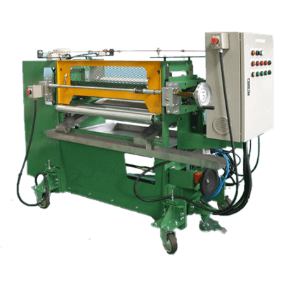
A roll coater is a machine that uses rollers to apply a coating to a flat surface, such as film.

Roll coaters apply paint, adhesives, chemicals, and other materials evenly. They are also equipped with a sputter source and plasma CVD, enabling continuous and high-speed deposition of barrier films, transparent conductive films, etc. Generally, it is limited to coating thin flat surfaces, such as sheets and films.

The applications are diverse depending on the combination of technologies, and various coating thicknesses and viscosities can be used. Therefore, the fields of application for roll coaters range from optics, liquid crystal products, and electronic components to chemicals and foodstuffs.

Uses of Roll Coaters

Roll coaters are used for functional films in optical products for tablets, smartphones, and other high-performance, low-profile devices, as well as for high-density, compact components. Film types include light control, anti-reflection, anti-glare, polarization, light diffusion, screen protection, and transparent conductivity.

They are also used in films for solar cells and secondary batteries. Types of films include reflector, light shielding, decorative, and heat dissipation. Thin film coating technology is used in automobiles, textiles, housing, electronic components, and semiconductors.

Principle of Roll Coaters

Roll coaters use multiple rollers to apply paints, adhesives, chemicals, conductive films, barrier films, and optical films to films and other materials. Rolls have various names such as “coater roll,” “doctor roll,” “feed roll,” “knife roll,” “guide roll,” and “gravure roll.”

Linear bearings are used to raise and lower the upper roller section to maintain high accuracy and smooth operation for a long time. The opening height can be adjusted. The rolls can be removed and reassembled in a short period for easy replacement.

The doctor roll open/close handles are integrated on both sides, enabling accurate and quick adjustment of application volume. Each roll is independently driven and can be divided into types according to the deposition process. The system is classified according to whether the coating amount is measured and selected and whether the coating liquid is before or after coating, and a combination of multiple systems can be used.

Types of Roll Coaters

Various types of roll coaters are in practical use. The two main types are the direct roll coater and reverse roll coater. They can also be classified according to whether the coating liquid is released or sealed.

1. Direct Roll Coater

The direction of rotation of the rolls and the direction of the object to be coated are the same. Also called natural roll coater. The material to be coated is fed between the rubber-lined coating roll and the steel backup roll.

2. Reverse Roll Coater

In this method, the coated object will travel in the opposite direction of the roll rotation. The coating rolls rotate in the opposite direction and roll over the coated object sent by the roller called the backup roll.

Compared to the direct roll, the reverse roll can apply a thicker coating at a time and has a cleaner surface, so it is widely used for primer coating, etc.

3. Post Metering Roll Coater

The post-metering coating method is a method in which extra coating liquid is applied once and then scraped off to the desired amount. It is called a knife coater or roll coater with blades, etc. The amount of scraping off and film thickness are determined by setting the shape and gap of the rolls.

Other Information on Roll Coaters

1. Roll Coaters for Special Purpose

Sputter Roll Coater
Sputter roll coaters use the sputtering method to deposit metal, transparent conductive, and optical films used in solar cells, touch panels, window films, and FPDs.

Plasma CVD Roll Coater
A plasma CVD roll coater uses electrical discharges generated between rollers to deposit silica films to achieve barrier properties used in organic EL, e-paper, lighting, solar cells, etc.

AIP Roll Coater
An AIP roll coater deposits metallic compound films by evaporating target materials using vacuum arc discharge.

2. Development and Trends of Roll Coaters

The problem with roll coaters is that the equipment is large due to the large area of the target material, and the setup and changeover are extensive. In recent years, roller cassettes have been introduced for coaters that can easily accommodate changes in coating conditions.

Coater equipment has become more sophisticated and complex, and it is desirable to have coaters that can measure, monitor, and record the condition of the coating surface, equipment, and workpiece using laser displacement gauges, cameras, and sensors.

カテゴリー
category_usa

Roller Pumps

What Is a Roller Pump?

A roller pump consists of a special elastic and resilient tube and a roller with multiple protrusions. The roller rotates and pushes the tube with its protrusions, pushing the fluid inside the tube to transport the fluid. It is also called a tube pump or hose pump. Since the fluid is transported by volume change in the tube, it is classified as a positive displacement pump. They are suitable for transporting fluids that are difficult to transport with gear pumps, such as slurries.

Uses of Roller Pumps

Roller pumps are used in situations such as medical equipment, chemical plants, commodity plants, and for transporting petroleum products. They are used in situations where they can be used to convey fluids that contain high levels of impurities, such as slurries, and in situations where changing pumps can take advantage of the characteristics that guarantee hygiene. When selecting a roller pump, it is necessary to consider the transport volume, low pulsation, power consumption, sanitation, and whether the fluid is suitable for transport by the roller pump.

Examples of roller pumps in use are shown below.

  • Conveying blood for dialysis
  • Conveying petroleum products to tanks
  • Conveying drinking water to plastic bottles

Principle of Roller Pumps

This section describes the operation of a roller pump. A roller pump consists of a tube, a roller, a motor to rotate the roller, a suction port, and an outlet. The tubing is elastic and resilient, and the rollers have dimensional protrusions that completely seal the tubing and allow it to rotate. Some products are equipped with valves on the inlet and outlet ports to adjust the flow rate.

During operation, the roller rotates, and its projections crush and move the tube. Fluid in the tube is pushed out and transported through the outlet. The inside of the tube, crushed and restored by the protrusions, is in a state of vacuum, and fluid is drawn into the tube by opening the valve. Since the protrusions deform the tube and transport the fluid as if pushing it out, the fluid does not easily clog inside the tube and can be transported stably.

カテゴリー
category_usa

Bearing Rollers


What Is a Bearing Roller?

Bearing Rollers

A bearing roller is a bearing that uses cylindrical rollers instead of balls as the rolling elements that support the load while rolling inside the bearing.

Bearing rollers with a larger diameter are called rollers, while those with a smaller diameter are called needles or needle rollers. Compared to ball bearings, which use a rolling element (ball), a bearing roller can support higher loads. There are various types of bearing rollers, depending on the application.

Uses of Bearing Rollers

Compared to ball bearings, bearing rollers can support larger loads and are used in automobiles and industrial machinery. The applications vary depending on the type.

1. Thrust Needle Bearing Roller

Thrust needle bearing rollers are used to support axial loads between parts rotating relative to each other in a planetary gear mechanism (planetary gears).

2. Needle Bearing Roller

Needle bearing rollers are used in the crankshafts of competitive bicycles. While ball bearings are used in the crankshafts of bicycles for daily use, needle bearings, and ball bearings are used in competition bicycles to reduce size and weight.

3. Tapered Bearing Roller

Tapered bearing rollers are used in the transmissions of automobiles. Automatic transmissions for front-wheel drive have a large gear on the final reduction shaft, and these gears are usually helical. The teeth of the helical gears are slanted to reduce noise and vibration when the gears mesh, but they also generate forces in three directions. The role of the tapered bearing roller is to support the forces in these three directions.

Planetary gears are also used in multi-stage step-type automatic transmissions, the forward/reverse switching mechanism of continuously variable transmissions (CVTs), and some sub-transmissions. The pinion in planetary gears is supported by a needle roller. Although the pinions are usually beveled, the needles can only support loads in two directions. The remaining thrust load is not supported by the needle, but by a washer on the end face of the pinion.

Principle of Bearing Rollers

In general, bearing rollers can support larger loads than ball bearings. The reason for this is bearing rollers have a cylindrical rolling element that makes linear contact with the inner and outer rings and raceways with which it comes into contact.

Since ball bearings are in point contact, the bearing roller has a larger contact area. The larger contact area reduces the stress (Hertzian stress) generated at the contact area.

The shape of the bearing can be cylindrical or conical, and changing this shape also changes the amount of load that the bearing can support. This also makes it possible to increase the load that can be supported by a single bearing without using multiple bearings, thus enabling compact specifications through weight reduction and miniaturization.

Types of Bearing Rollers

Similar to ball bearings, bearing rollers can be broadly classified into two types: radial bearings, which support radial loads (perpendicular to the axis of rotation), and thrust bearings, which support thrust loads (in the same direction as the axis of rotation). Bearings with relatively large rollers are called bearing rollers, while bearings with narrower rollers are called needle bearing rollers. Typical types are as follows:

1. Radial Bearing Roller

Radial bearing rollers are capable of bearing radial loads acting at right angles to the shaft. Compared to ball bearings, which use balls instead of rollers, radial bearing rollers can support larger radial loads. By changing the shape of the rollers, a wider variety of types is available.

2. Needle Bearing Roller

A needle roller is used as the rolling element between the inner and outer rings of a bearing roller. By making the rolling element as thin as a needle, the height of the cross section is smaller than that of a bearing roller, contributing to the reduction of machine weight and size. In addition to radial bearings, thrust bearings are also available and are used in a variety of applications, including automobiles and electrical machinery.

3. Taper Bearing Rollers

Tapered bearing rollers are radial bearing rollers with tapered rollers and sloped raceways on the inner and outer rings instead of flat. The tapered rollers and beveled raceways can support large radial loads and large thrust loads at the same time.

It is mainly suitable for supporting loads in three directions generated by helical gears. However, a single bearing can only support thrust loads in one direction. It is common to use a combination of two tapered bearing rollers in opposite directions.

カテゴリー
category_usa

Roller Followers

What Is a Roller Follower?

Roller Followers

A roller follower is a type of compact and highly rigid bearing incorporating a needle bearing inside.

Its outer ring, in direct contact with the rolling surface, is thick-walled, hard, and features a high-precision surface. This design allows them to withstand high loads and impact loads, making them suitable for use as guide rollers in cam mechanisms and linear motion systems.

Roller followers, with their inner diameter as an inner ring, offer flexibility in shaft settings, enabling their use as compact guide rollers or cam followers with extended shafts.

These components are used in various applications, including eccentric rollers, guide rollers, rocker arm rollers, cam rollers, and pressure rollers.

Applications of Roller Followers

Roller followers are employed in scenarios where direct contact and rotation with cam mechanisms are required. Some common applications include:

Cam Mechanisms

These mechanisms, which alter motion direction, benefit from roller followers due to their ability to handle high loads and high-speed operation. Their adaptable shaft length makes them suitable for different types of cams, such as groove cams.

  • Guide Rollers: Roller followers serve as efficient guide rollers, facilitating smooth and straightforward installation and operation in conveyor systems.
  • Wheels: These components can be used as simple wheels for moving pallets and jig tables without needing a cart.

Principle of Roller Follower

Roller followers operate by supporting radial loads while minimizing friction. This is achieved through cylindrical rollers (needles) placed between the inner and outer rings. The rollers rotate, allowing smooth rolling of the inner and outer rings.

Internally, these bearings are typically grease-filled for lubrication. For long-term or high-speed applications, lubrication ports and holes can be added for maintenance.

Roller followers are available in two needle arrangements: full complement and with cage. The full complement type, with more needles, is ideal for high loads but not for high-speed rotation due to friction. The caged type, suitable for high-speed rotation, has fewer needles and thus a lower load capacity.

The outer ring’s rolling surface can be cylindrical for a larger contact area and higher track load capacity or spherical to compensate for any misalignment, ensuring smooth rotation.

Types of Roller Followers

Roller followers are categorized into non-separating and separating types:

Non-separating Type

This type features a steel plate press-fitted into the outer or inner ring, creating a labyrinth seal that prevents foreign matter entry and keeps side plates intact. It is designed for smooth rotation under axial and moment loads, and sealed versions have additional rubber seals for enhanced protection.

Separated Type

The separated type lacks a flange on the outer and inner rings, allowing each component to be separated and replaced individually. This design offers compactness and ease of assembly compared to the non-separated type.