カテゴリー
category_usa

Ceramic Resonators

What Is a Ceramic Resonator?

A ceramic resonator is an electronic component that uses the vibration of a ceramic material, commonly lead zirconate titanate, to create oscillations at a specific frequency. These devices offer a more cost-effective and compact solution compared to quartz-based oscillators, making them suitable for many electronic applications where high precision is not critical.

Uses of Ceramic Resonators

Ceramic resonators are typically used in oscillation circuits for clocks in digital circuits, particularly where miniaturization and weight reduction are prioritized:

  • Digital clocks and smartwatches
  • Timers for home appliances like microwave ovens
  • Automobile engine control units (ECUs)
  • Audio equipment and musical instruments tuning
  • Clock signal generation in data communication equipment
  • Measurement and control devices timing control
  • Robots and automatic control systems
  • Medical device timers and controllers
  • Electronic locks and security systems timing control
  • Battery management in mobile devices

Principle of Ceramic Resonators

The operation of ceramic resonators is based on the piezoelectric effect, where physical deformation and electrical signals are interconverted in ceramic materials:

1. Piezoelectric Effect

Applying an electrical signal to the ceramic material causes it to deform and vibrate, generating a frequency determined by its physical properties.

2. Vibration Control

The resonator stabilizes the vibration through a feedback control mechanism, using the voltage generated from the ceramic’s vibration.

3. Signal Output

The ongoing vibration of the ceramic material produces a voltage, which is then used as a stable clock frequency output.

Characteristics of Ceramic Resonators

Compared to crystal and LC oscillators, ceramic resonators offer several advantages:

1. Compact and Lightweight

Due to the small size of the ceramic materials, the overall circuit can be made compact and light.

2. Cost-Effective

Ceramic materials are relatively inexpensive, making these resonators a cost-effective option for mass production.

3. Low Power Consumption

They generally operate with low power consumption, enhancing energy efficiency in battery-powered devices.

4. High Reliability

Ceramic materials are robust and provide stable oscillations over a wide range of temperatures.

5. Wide Frequency Range

These resonators can operate across various frequencies, suiting a range of applications.

Limitations of Ceramic Resonators

Despite their advantages, ceramic resonators have certain limitations compared to crystal and LC oscillators:

They offer less frequency stability and are not ideal for high-frequency or specific frequency range applications. Unlike LC oscillators, their oscillation frequency is not easily variable, limiting their flexibility in some use cases.
カテゴリー
category_usa

Bus Switches

What Is a Bus Switch?

In electronic circuits, a bus switch is a device that electrically conducts (turns ON) or interrupts (turns OFF) a signal. This is achieved using MOSFETs. The basic role of a bus switch is the same as that of a mechanical switch.

Since it is a switch, it naturally operates in both directions, so there is no need to worry about the direction of the signal.

In the case of a mechanical switch, it only conducts the signal by turning it ON or interrupts it by turning it OFF. On the other hand, some bus switches have a built-in function to amplify the signal or, conversely, to reduce its level.

Uses of Bus Switches

Devices that turn signals on and off in electronic circuits include bus switches and analog switches.

Analog switches are devices designed to perform switching operations in analog circuits. On the other hand, bus switches are devices for digital circuits and are inserted between the CPU and peripheral ICs.

Bus switches are used not only to conduct and disconnect signals but also to switch the connection destination. In the simplest case, for example, if outputs B and C are placed in relation to input A, the bus switch switches from conduction between A and B to conduction between A and C.

Bus switches used in electronic circuits are designed for use in relatively high-speed circuits due to their high-speed switching characteristics.

Principles of a Bus Switch

A typical bus switch is made by combining two MOSFETs: a P-CH MOSFET and an N-CH MOSFET with their gates directly connected and their drains directly connected in parallel.

By inputting a signal from the gate, either the P-CH or N-CH MOSFET will always be in a conducting state, and this is used as the output signal.

A device similar to a bus switch is a bus buffer. A bus buffer has a large fanout number (high drive capability), but there is a delay in switching.

The choice of which device to use should be determined based on the application in the circuit.

Types of Bus Switches

In addition to the aforementioned type that consists of P-CH and N-CH MOSFETs connected in parallel, there are also N-CH type and charge pump type bus switches.

The N-CH type switches ON/OFF by applying a specified voltage to the gate and inputting a signal between the drain and the source.

The charge pump type is made using only N-CH MOSFETs to improve the output signal voltage range.

カテゴリー
category_usa

Power Analyzers

What Is a Power Analyzer?

Power Analyzers

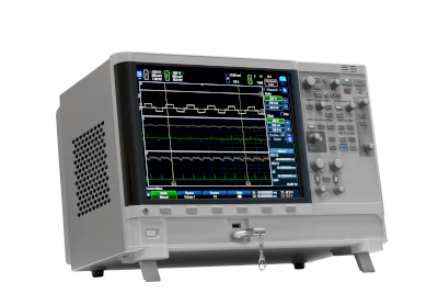
A power analyzer is a device designed to measure the power output of electrical equipment. It enables the assessment of energy conversion efficiency and the identification of malfunctions caused by voltage drops. Although power can be measured with a wattmeter, power analyzers offer the additional capability to measure other parameters such as voltage, current, and frequency, which is not possible with standard power meters. These devices feature multiple channels on the display screen, allowing for the customization of displayed parameters according to the user’s needs.

Uses of Power Analyzers

Power analyzers are instrumental in measuring the efficiency of power generation from renewable energy sources like solar and wind power. Despite the growing popularity of renewable energy for its environmental benefits, it faces challenges such as dependency on weather conditions and generally lower efficiency compared to conventional thermal power generation. Power analyzers help in ensuring the effective supply of electricity and in implementing backup systems when power generation efficiency drops due to energy shortages.

Principle of Power Analyzers

Power analyzers assess the power flow within electrical equipment, employing different calculation methods for DC and AC circuits. In DC circuits, power is calculated by multiplying voltage and current. For AC circuits, however, where current values fluctuate, simple multiplication is insufficient. Power analyzers calculate the RMS (root mean square) value of electrical signals to provide a reliable measure of power current for AC circuits, facilitating accurate power calculations.

Features of Power Analyzers

Modern power analyzers offer:

1. Portability

Designed for field measurements, such as those needed for solar panels, power analyzers are now more compact and lightweight, thanks to advances in technology that condense computing functions into the power analysis engine.

2. Environmental Adaptability

They are engineered for accurate measurements in various temperature conditions, including rapidly changing environments found in constant-temperature rooms and engine rooms.

3. Data Transmission

Wireless technology adapters, such as Bluetooth, enable the transmission of measured data to data loggers or similar devices.

4. Diversity of Interfaces

They support a broad range of standards including USB, LAN, GP-IB, and RS-232C, and offer capabilities for external control and synchronization between units.

Types of Power Analyzers

Various power analyzers available include:

1. Oscilloscope Integrated Type

Integrating high-resolution oscilloscopes, these models combine power and waveform measurements in a single device, offering a solution that was not available in earlier power analyzers that lacked waveform observation capabilities. Several manufacturers now offer similar integrated oscilloscope models.

2. High-Precision Measurement Models

These models provide high accuracy in power measurement across a broad frequency range, suitable for detailed analysis of phenomena with large variation ranges and for measuring the switching drive of inverters, with some capable of measuring frequencies above 100 kHz and below 1 Hz.

How to Select Power Analyzers

Power analyzers fall into two main categories based on price: low-priced and high-end models. The selection depends on the required accuracy and frequency range of power measurement. For measurements over 100 kHz, including frequencies of 1 Hz or below, or when high measurement accuracy is essential, a high-end model is recommended. These models are ideal for detailed analysis of wide variation ranges and for measuring inverters and switching drives. For other applications, a mid-range model may suffice.

カテゴリー
category_usa

Voltage Detectors

What Is a Voltage Detector?

A voltage detector is an electronic device used to detect specific voltage levels.

It monitors whether the power supply voltage is within a specified range, ensuring stable operation and proper control.

Uses of Voltage Detectors

Voltage detectors are crucial in monitoring and controlling power supply stability, ensuring system reliability and safety.

1. Reset Circuits for Microprocessors

They monitor supply voltage and generate a reset signal at the proper voltage level, especially during power-on, allowing microcontrollers or microprocessors to initialize successfully and start from a reset state.

2. Control of Power Supply Units

Integrated into power supply units, voltage detectors detect power supply voltage abnormalities and control the circuit to maintain stable power.

3. Battery Management Systems

In battery management systems, voltage detectors monitor battery voltage, detecting overvoltage or undervoltage during charging or discharging, aiding in stable battery operation.

4. System Fail-Safe Functions

They are also employed in system fail-safe functions, safely shutting down systems or activating protective functions upon detecting power failures or unstable voltages.

Principle of Voltage Detectors

Voltage detectors contain a circuit that detects voltage levels at the input terminals. Their typical configuration and operating principle include:

1. Reference Voltage Source

They require a stable, accurate reference voltage for comparison with the input voltage, either produced internally or supplied externally.

2. Comparator

Comparators within voltage detectors compare the input voltage with the reference voltage, outputting the result.

3. Threshold Setting

They set a threshold voltage as the reference. The comparator then determines if the input voltage is above or below this threshold, making a stable threshold voltage crucial.

4. Output Signal

Voltage detectors output a digital signal indicating whether the input voltage is above or below the threshold, which is crucial for monitoring and controlling power supply stability.

Types of Voltage Detectors

Various types of voltage detectors exist, each with specific applications:

1. Fixed-Type Voltage Detector

Fixed threshold voltage detectors are used for power supply monitoring and reset signal generation.

2. Variable-Type Voltage Detector

Variable-type detectors allow users to adjust the threshold voltage, which is suitable for monitoring diverse voltage levels.

3. Dual Voltage Detector

Dual voltage detectors have two independent thresholds for monitoring and controlling different voltage levels.

4. Overvoltage Detector

Specialized for detecting overvoltage, these detectors activate countermeasures when the input voltage exceeds a set threshold.

5. Low-Voltage Detector

Designed for low voltage detection, they trigger countermeasures like current supply limitation when the input voltage falls below a specified threshold.

6. Reset IC

Mainly used in microcontrollers and microprocessor reset circuits, they detect when the power supply stabilizes and outputs a reset signal, initiating normal operation.

カテゴリー
category_usa

Universal Counters

What Is a Universal Counter?

Universal Counters

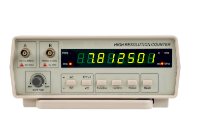
A universal counter is an advanced type of counter for electrical signals, offering additional functionalities beyond the standard period and frequency measurement capabilities of a frequency counter. It can measure pulse width, phase, period relative to pulse width, and the rise and fall times of signals. Additionally, it measures the time difference between two input signals and their frequency ratio, making it a versatile measuring instrument.

Some models can analyze and display data stored over a certain period.

Uses of Universal Counters

Universal counters are instrumental in product development, particularly for circuit design and operational verification of boards based on design results. They are also valuable in technical education settings.

On production and inspection lines, these counters are useful for verifying if the expected frequency and other parameters meet specified values.

While historically expensive due to the need for dedicated logic circuits, recent advancements in low-cost, high-functionality microcomputers and peripheral ICs have made universal counters more affordable.

Principles of Universal Counters

The universal counter measures frequency, a numerical indicator of the number of signals per unit time in a repetitive signal, through the following process:

Initially, input signals are waveform-shaped into clean signals for accurate measurement (signal A). Simultaneously, a gate signal (signal B) specifies the measurement period for signal A. The counter takes the AND of signals A and B and counts the outputs. By counting the number of A signals within a specific period of signal B, the frequency of signal A is determined and displayed on an LCD or through the counter interface.

Most universal counters simplify circuit configuration by using a built-in microcontroller to set the frequency of the gate signal and count the gated signals.

カテゴリー
category_usa

Lithium Ion-Capacitors

What Is a Lithium-Ion Capacitor?

A lithium ion capacitor is an energy storage device that combines the properties of an electric double-layer capacitor and a lithium ion battery.

It is abbreviated as “LiC” because it is written as “lithium-ion capacitor” to distinguish it from LiB, which is a lithium-ion battery.

Compared to the electric double layer capacitor (EDLC), the LIC has a higher energy density and a larger power density than the LIB. Due to these differences in characteristics, there are different types of lithium-ion capacitors for different applications.

Uses of Lithium-Ion Capacitors

A Lithium-Ion Capacitor is an energy storage material with high energy density and output density, as well as excellent safety and durability. They are expected to replace lithium-ion batteries in fields requiring high output, which lithium-ion batteries are not good at. It can also be used in situations requiring energy density, in which electric double-layer capacitors are not good at, and in applications where high temperature and high voltage loads are applied.

It features excellent rapid charge/discharge characteristics, high- temperature characteristics, durability, and reliability, and can be handled safely. Because they can be used stably for a long time, even after repeated charging and discharging, they are being considered for a wide range of applications, including solar power generation, wind power generation, instantaneous voltage drop compensation devices, industrial machinery, and transportation and vehicle-related applications.

Lithium-Ion Capacitor have also been considered for use as a power source for electric vehicles, but their energy density is lower than that of lithium-ion batteries and they are inferior in terms of cruising range, so lithium-ion batteries are mostly used for electric vehicle applications. However, compared to lithium-ion batteries, lithium-ion capacitors are superior in terms of rapid charging and discharging, so they are being considered for use in vehicles with a fixed route, such as trams and buses, where they are charged at stops and stations to store power for the journey.

Principle of Lithium-Ion Capacitors

A Lithium-Ion Capacitor consists of a cell, cathode, anode, and electrolyte, and can be charged and discharged repeatedly by adsorption and desorption of lithium ions in the electrolyte to the cathode and anode. When voltage is applied to a Lithium-Ion Capacitor, lithium ions are adsorbed on the negative electrode and anions are physically adsorbed on the positive electrode.

When discharged from this state, the lithium ions on the negative electrode are desorbed and lithium ions are adsorbed on the positive electrode after the anions are desorbed. With charging and discharging, the positive electrode uses physical adsorption and desorption as in an electric double layer capacitor, while the negative electrode uses adsorption and desorption of lithium ions, involving a chemical reaction as in a lithium-ion secondary battery.

Lithium-Ion Capacitors require a higher cell voltage to increase energy density. This is because the amount of energy stored is expressed as E = CV2/2 (C: capacitance, V: cell voltage). The voltage is the potential difference between the positive and negative electrode potentials, but raising the positive electrode potential causes oxidative degradation of the material, so in Lithium-Ion Capacitor, the negative electrode is doped with lithium in advance at the manufacturing stage to lower the negative electrode potential so that the potential difference increases during charging.

Structure of Lithium-Ion Capacitors

A capacitor is a capacitor, which mainly consists of a cell, a positive electrode, a negative electrode, an electrolyte, and a separator. Lithium-Ion Capacitor uses activated carbon as the active material of the positive electrode, and the active material of the negative electrode has a small specific surface area, similar to that of a lithium-ion battery.

Carbon materials such as hard carbon, which can be doped with lithium ions, are used. Aluminum is used for the positive electrode and copper for the negative electrode current collectors, but they are porous because they must allow lithium ions to permeate through them for lithium doping in the manufacturing process described below.

As electrolyte, organic electrolyte made by dissolving lithium salts such as LiBF4 (lithium tetrafluoroborate) and LiPF6 (lithium hexafluorophosphate) in organic solvents is usually used. Separators with excellent lithium ion permeability and electrolyte impregnation properties are used.

カテゴリー
category_usa

Reflow Ovens

What Is a Reflow Oven?

Reflow Ovens

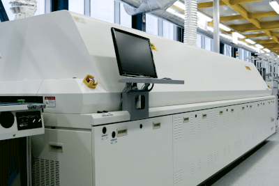
A reflow oven is a heating device used in the production of printed circuit boards (PCBs), bonding electronic components to boards using solder.

Operating typically at temperatures between 150°C and 230°C, the reflow oven’s temperature range may vary depending on whether the solder contains lead.

Uses of Reflow Ovens

Reflow ovens are crucial in bonding electronic components to PCBs in unit board production. They are particularly advantageous when soldering a large number of components or those with small bonding surfaces. The precision of reflow ovens becomes essential as components get smaller and more densely packed, avoiding issues like weak adhesion or short circuits often encountered in manual soldering.

Principles of Reflow Ovens

The reflow oven heats up by blowing hot air inside, with the temperature increased by directing hot air perpendicularly onto the board. When the solder, placed on the board, melts due to the heat, electronic components positioned on the solder adhere to the board. After soldering, the oven cools down, solidifying the solder and securing the components to the board.

Other Reflow Oven Information

1. Difference Between Flow Oven and Reflow Oven

A flow oven, used for flow soldering, involves boards passing over a bath of molten solder, requiring a solder bath and resulting in larger equipment. In contrast, a reflow oven utilizes paste solder or cream solder, applied to the board or component, which forms a metallic bond when heated in the oven, eliminating the need for a solder bath.

2. Filling the Reflow Oven with N2 Gas

Filling the reflow oven with nitrogen gas (N2) can reduce the oxygen concentration, preventing oxidation of the rosin in the solder paste. However, this can sometimes lead to the soldering appearing cleaner than its actual quality, potentially passing inspection even if the bonding is insufficient. Decisions regarding the use of nitrogen gas should involve consultation with manufacturing, design departments, or contractors.

カテゴリー
category_usa

Piezoelectric Actuator

What Is a Piezoelectric Actuator?

A piezoelectric actuator is a device that converts electrical energy from sources like ICs into physical kinetic energy, manifesting as linear motion or deformation. This conversion is achieved through a piezoelectric element within the actuator, making piezoelectric actuators distinct for their high precision, rapid response, and absence of electromagnetic noise.

These actuators are notable for their compact size, lack of a need for driving coils, and low power consumption, making them ideal for precision instruments such as digital cameras and mobile devices.

Uses of Piezoelectric Actuators

Piezoelectric actuators find applications across various industrial products and household appliances, particularly in precision equipment. They are valued for their compactness, swift response, and energy efficiency. Uses span single-lens reflex cameras, hard disk drives, inkjet printers, medical devices, and more.

Principle of Piezoelectric Actuators

The operation of piezoelectric actuators is based on the inverse piezoelectric effect, where applying an electric field to a piezoelectric material causes it to deform. This effect is harnessed to achieve precise mechanical movement through electrical control. By thinning the ceramic substrate, these actuators can operate at lower voltages, enhancing their efficiency.

Other Information on Piezoelectric Actuators

1. Comparison With Electromagnetic Actuators

Piezoelectric actuators offer several advantages over traditional electromagnetic actuators, including the potential for greater displacement and reduced drive voltages. Electromagnetic actuators, requiring coils, struggle with miniaturization and cannot match the precision, controllability, and energy efficiency of piezoelectric actuators.

2. Hysteresis of Piezoelectric Actuators

While piezoelectric actuators can achieve nano-level control, they exhibit hysteresis, meaning their displacement is not perfectly linear with control voltage. This necessitates external precision control mechanisms, such as strain gauges and ASICs, for accurate operation.

3. Development of Energy Harvesting Applications

Interest in piezoelectric actuators for energy harvesting is growing, driven by environmental sustainability goals. These devices can convert mechanical displacement into electrical energy, with potential applications in power generation from environmental sources, including vibration, light, heat, and electromagnetic waves. This technology is also being explored for use in wireless communication tags powered by vibration energy.

カテゴリー
category_usa

Variable Inductors

What Is a Variable Inductor?

An inductor (coil) is an electronic component made by wrapping copper wire around an iron core. When an electric current is applied to the copper wire in the inductor and the amount of the current is varied, it generates an induced electromotive force. This is called inductance and is expressed in units of Henleys (H).

A variable inductor is a device whose inductance can be varied by placing a small driver or adjusting the rod on top of the device and rotating a knob to slide the internal iron core up and down.

Applications of Variable Inductors

In general, inductors are used in many electrical products. A familiar example is an AC transformer.

Since it transmits high frequencies, it is also used in various wireless devices (WiFi and non-contact IC chips) and microwave ovens. They are also used in fluorescent light ballasts and various electrical products and are indispensable components for rectifying electronic circuits.

Variable inductors are used in a limited number of applications, such as tuning circuits for car tuners, but are now used less frequently due to the digitization of circuits.

Principles of Variable Inductors

The basic principle of operation of variable inductors is the same as that of fixed inductors.
When a DC current is applied to the coil, a magnetic field is generated in the iron core, and the core becomes an electromagnet.

When a voltage is initially applied or when the voltage is lowered, an induced current flows instantaneously in the moving wires. This causes electrical energy to be stored in the form of a magnetic field.

After a magnetic field of a certain strength is generated, a direct current flows, just like an ordinary copper wire. In contrast, when an alternating current flows through an inductor coil, a magnetic field of varying magnitude is generated in the iron core.

As the magnetic field changes, induced electromotive force in the opposite direction of the current is generated, resulting in resistance (inductance). If an alternating current continues to flow, an induced electromotive force in the opposite direction is always generated, so the current continues to have difficulty flowing.

In the case of an inductor coil, DC current can pass through smoothly, but AC current is challenging to flow because of the resistance generated. Therefore, it is an electronic component with the opposite characteristics of a capacitor, allowing AC current to pass through but not allowing DC current to pass through.

カテゴリー
category_usa

Optical Connector

What Is an Optical Connector?

An optical connector is a terminal for connecting an optical fiber line.

In the Internet connection, the conventional method used telephone lines, but now optical fiber lines using optical communication have become the mainstream. Optical connectors are indispensable components for connecting optical fiber cables.

Compared to fusion splicing, which is another splicing method, optical connectors are highly versatile because they can be easily and accurately connected and disconnected.

Uses of Optical Connectors

As mentioned above, optical connectors serve as connection terminals in optical fiber lines. There are a wide variety of types, and different types of optical connectors are used for different purposes. The most common type is the “push-pull” type, which has a structure that allows easy insertion and removal. For applications where insertion and removal are rarely required, the “screw-tightening type” is recommended, as it provides a strong connection.

In addition to fiber-optic lines, optical connectors are sometimes used in devices that handle light, such as optical measuring instruments.

Principle of Optical Connectors

A typical optical connector consists of a ferrule and housing that fixes the tip of an optical fiber. In an optical fiber line, the principle of connector connection is to butt these tips directly against each other. Even the slightest misalignment of the connection causes an increase in loss (connection loss), so a structure that allows a high-precision connection is necessary.

The device to which an optical connector is connected is called an optical adapter. The optical adapter has a built-in split sleeve inside that matches the shape of the connector, enabling a high-precision connection.

The connection surface (end face) is finished by polishing. The most common method is PC polishing, also known as spherical polishing. The spherical end faces are butted together in such a way that the tops are concave due to the springs inside the connector. This prevents the formation of an air layer between the optical fibers, thereby enabling a connection with minimal loss.