What Is a Frequency Counter?


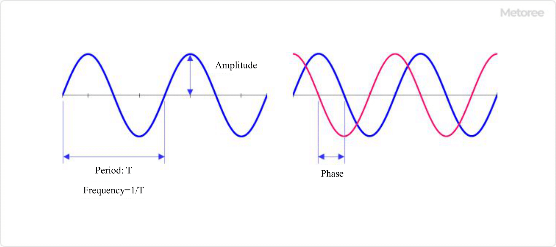
Figure 1. Three parameters of an electrical signal waveform
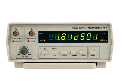
A frequency counter is a digital device used to measure the frequency occurring in an electronic circuit.
An electrical signal can be expressed in terms of three parameters: frequency, amplitude, and phase. It is also possible to determine the period by the reciprocal of the frequency. Frequency measurement is an important parameter in the basic measurement of electrical signals.
In addition to the frequency counter, those with several additional functions, such as duty cycle measurement, pulse rise time, and time interval, are called universal counters.
Uses of Frequency Counters
Frequency counters are used as basic measuring instruments in electrical signal measurement, like ammeters and voltmeters. Although some products are available as stand-alone frequency counters, many products have been developed with frequency counter functions as part of the functions of devices with many functions, such as digital multimeters, oscilloscopes, and optical spectrum analyzers.
Frequency counters are characterized by the fact that their principle is very simple. Since it is possible to make your own frequency counter, kits are available. Frequency counter kits are available from various companies for several tens of MHz. The reason for this is that direct-type frequency counters are characterized by their uncomplicated operation.
Some multi-testers are equipped with a frequency measurement range, and these types are especially useful at sites where large measurement equipment cannot be brought in, because they can be handled easily. However, while they have the advantage of being easy to use, their disadvantage is that they are not suitable for applications that require high frequencies or a large number of significant digits.
Since most of the kits are LSI-based, you cannot learn the entire structure, but you can get a feel for it.
Principle of Frequency Counter

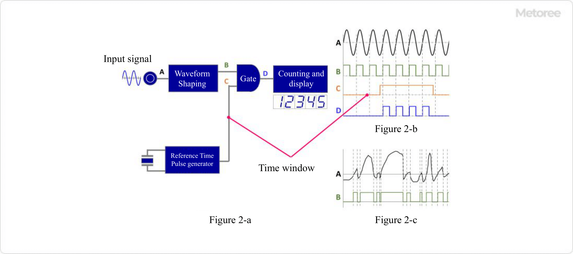
Figure 2 Principle of frequency counter (Direct method)
A frequency counter consists of a waveform shaping circuit, a gate, a crystal oscillator, and a counting circuit.
1. Waveform Shaping Circuit
Converts the input signal into a “pulse train.”
2. Crystal Oscillator
Generates pulses with a fixed time width. Generates a time window (gate time) for measuring the pulse train described earlier, and the time window serves as a window for measuring the frequency.
3. Measurement Circuit
The frequency of the original signal is measured by counting the number of pulses in the time window. The resolution of the frequency measurement is determined by the time width of the time window generated by the crystal oscillator. For example, a time window of 1 second allows the frequency to be displayed in units of 1 Hz, a time window of 0.1 second is 10 Hz, and so on. The resolution is proportional to the inverse of the time window width.
In frequency counters, the most error occurs at the point where the pulse train is generated, especially if the input signal contains noise, which can cause the rising edge of the pulse to be unstable or generate extra pulses that should not be there.
The method used to prevent the generation of errors is to perform repeated measurements and average out the noise components. This reduces the errors that occur when generating pulse trains.
Frequency Counter Measurement Method

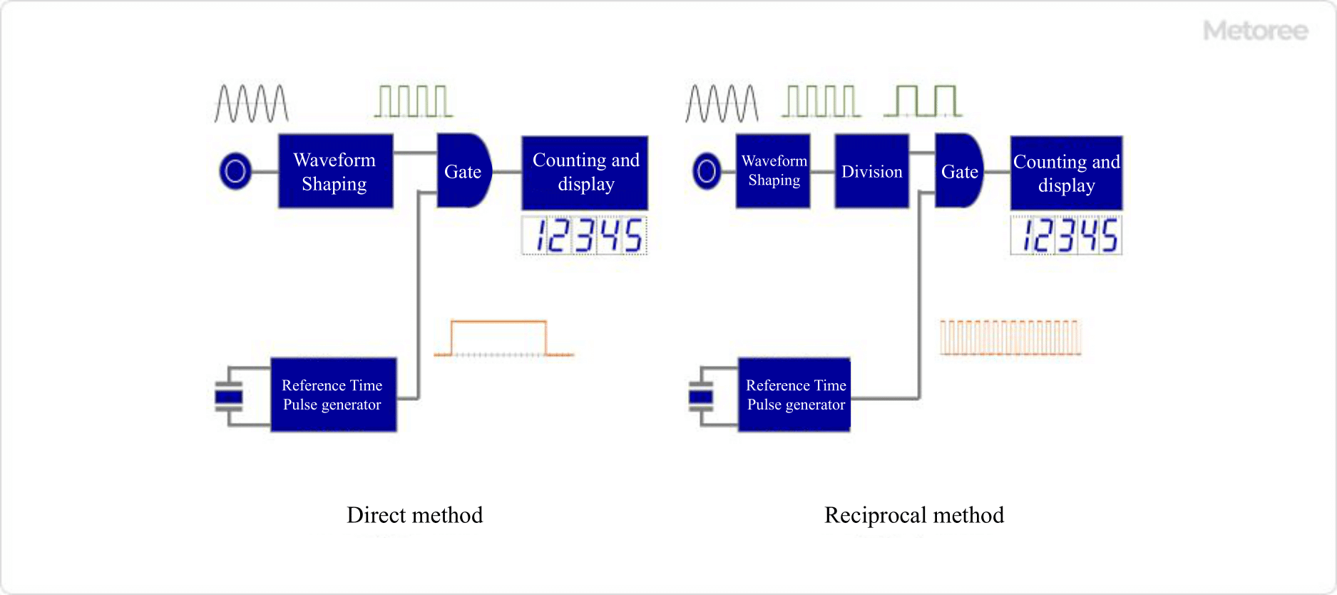
Figure 3. Frequency counter system
A frequency counter is a device that measures the frequency of an input signal and displays the result. There are two measurement methods: the “direct method,” which has been used for a long time because it is easy to implement, and the “reciprocal method,” which is expensive but can obtain a high number of significant digits.
1. Direct Method
Zero Point Cross Measurement
The direct method frequency counter measures the number of times the frequency of the input signal crosses at the zero point. If the input signal is a sine curve, it counts the number of times it crosses either down or up to the zero point. The advantage of the direct method frequency counter is that it can be easily implemented using only hardware. For this reason, this method has been used for a long time, and its number of zero point crossings per second is displayed as a frequency measurement.
The direct method frequency counter is characterized by the fact that an accurate reference clock is made inside the device, and the number of times the zero point is crossed is measured by opening a time window for that amount of time.
Number of Significant Digits in Measurement
The number of significant digits in a direct method frequency counter is determined by the time width of the time window and the input frequency. For example, if the input frequency is 1 GHz and the time window is 1 second, the measured value is 1×10^9 and the number of significant digits is 10. If the input frequency is 1 kHz, the number of significant digits is 4, and the resolution for both is 1 Hz.
For example, if the time window is 100 seconds, the number of significant digits is 6 at 1 kHz, and the resolution is 0.01 Hz. However, taking at least 100 seconds for a single measurement is not realistic and significantly reduces workability. It should also be used with the understanding that the measured value will always have a quantum error of ±1.
If you are only measuring high-frequency signals, you can use a direct method frequency counter without any problems, but to increase accuracy with the direct method, you need to increase the time window time width. However, the direct method has the disadvantage of extremely low efficiency because the longer the time window, the longer the time required for each measurement. Frequency Counter of “Reciprocal Method” is an alternative in such a situation.
2. Reciprocal Method
A reciprocal frequency counter counts the input waveform as it is or divides it by an internal reference clock. The advantage of this method is that a high number of significant digits can be obtained, especially when measuring low frequencies. The number of significant digits in a reciprocal Frequency Counter is determined by the internal reference clock and gate time, and is not affected by the input frequency.
For example, if the internal reference clock is 10 MHz and the gate time is 1 second, the number of significant digits is 7. Although the reciprocal method is capable of obtaining a high number of significant digits in measurements in the low frequency counter range, it has the disadvantage of being expensive because the operation of the counter itself is complex.