カテゴリー
category_usa

Optical Connector

What Is an Optical Connector?

An optical connector is a terminal for connecting an optical fiber line.

In the Internet connection, the conventional method used telephone lines, but now optical fiber lines using optical communication have become the mainstream. Optical connectors are indispensable components for connecting optical fiber cables.

Compared to fusion splicing, which is another splicing method, optical connectors are highly versatile because they can be easily and accurately connected and disconnected.

Uses of Optical Connectors

As mentioned above, optical connectors serve as connection terminals in optical fiber lines. There are a wide variety of types, and different types of optical connectors are used for different purposes. The most common type is the “push-pull” type, which has a structure that allows easy insertion and removal. For applications where insertion and removal are rarely required, the “screw-tightening type” is recommended, as it provides a strong connection.

In addition to fiber-optic lines, optical connectors are sometimes used in devices that handle light, such as optical measuring instruments.

Principle of Optical Connectors

A typical optical connector consists of a ferrule and housing that fixes the tip of an optical fiber. In an optical fiber line, the principle of connector connection is to butt these tips directly against each other. Even the slightest misalignment of the connection causes an increase in loss (connection loss), so a structure that allows a high-precision connection is necessary.

The device to which an optical connector is connected is called an optical adapter. The optical adapter has a built-in split sleeve inside that matches the shape of the connector, enabling a high-precision connection.

The connection surface (end face) is finished by polishing. The most common method is PC polishing, also known as spherical polishing. The spherical end faces are butted together in such a way that the tops are concave due to the springs inside the connector. This prevents the formation of an air layer between the optical fibers, thereby enabling a connection with minimal loss.

カテゴリー
category_usa

Photomultiplier Tube

What Is a Photomultiplier Tube?

A photomultiplier tube is one of the light sensors that can convert light into electricity. The PMT consists of a glass tube in a vacuum with an incident window, a photocathode, a dynode, and other components. The principle is based on the external photoelectric effect, a phenomenon in which electrons are emitted from the surface of a metal when light is irradiated on it in a vacuum.

Since even very weak light signals can be converted into large electrical signals, photomultiplier tubes are used as photodetectors in spectrophotometers, spectroscopic analyzers, and other instruments.

Applications of Photomultiplier Tubes

Photomultiplier tubes are very sensitive and can convert very weak light into a sufficient amount of electrical signals. On the other hand, they also have disadvantages, such as requiring high voltage for use and being prone to picking up noise.

They are used in detectors for optical analyzers, such as UV-visible spectrophotometers and emission spectrometers. They are also used in dust counters to measure particles in the atmosphere, laser radar (LiDAR) to detect scattered light from suspended particles in the air, and medical devices such as PET and CT for cancer screening.

Photomultiplier Tube Principle

A photomultiplier tube is an optical sensor that can detect light and convert it into an electrical signal. A window through which light enters, a photocathode, a focusing electrode, a dynode, and an anode are mounted inside a glass tube under vacuum conditions.

PMTs, apply the external photoelectric effect, in which electrons are emitted when light strikes them. This phenomenon occurs when light is irradiated onto a metal under a vacuum, causing electrons to be emitted from the metal surface. When light strikes the photocathode, electrons are knocked out of the photocathode. The knocked-out electrons are accelerated by the focusing electrode, and when they strike the dynode, multiple secondary electrons are emitted. The emitted secondary electrons then collide with the next dynode, where more secondary electrons are emitted. Repeating this process increases the number of electrons many times over, and eventually, a sufficient amount of electrons are detected as an electrical signal.

Solar cells and photodiodes can also output electrical signals from light, but PMTs are superior because they can output electrical signals from feeble light.

カテゴリー
category_usa

High-Voltage Resistor

What Is a High-Voltage Resistor?

A high-voltage resistor is designed to handle significantly high voltages, typically in the kilovolt (kV) range. These components, which can have resistance values up to 100 Ω, are crucial in circuits for controlling the flow of electricity, thereby ensuring circuit stability and signal integrity. Their construction from high-resistivity materials allows them to maintain superior insulation properties, making them integral in managing high-voltage applications.

Uses of High-Voltage Resistors

Due to their ability to withstand high voltages, these resistors find applications across a wide array of high voltage circuitry in sectors including:

1. Medical Applications

Utilized in various medical equipment, from home health devices to advanced hospital machinery, including X-ray and ultrasound machines, defibrillators, and patient monitoring systems.

2. Automotive Applications

Key in electric and hybrid vehicle systems such as engine and inverter controls, battery management, and navigation systems, enhancing efficiency and safety.

3. Industrial Applications

Employed in control circuits, automation, power supplies, and test/measurement equipment, supporting the backbone of industrial operations.

4. Communication Applications

Critical in telecommunications for devices like smartphones, base stations, and IoT systems, ensuring reliable signal transmission and power management.

5. Energy Applications

Applied in smart meters, energy storage systems, and LED lighting solutions, contributing to energy efficiency and sustainability.

Principle of High-Voltage Resistors

A high-voltage resistor comprises a substrate, insulative base, resistive element, protective coating, and internal and external electrodes. Its construction, often using alumina for insulation, is tailored to endure high voltages. The resistive element may feature solid, meander, or serpentine patterns to optimize voltage withstand capability. Adjustments to the resistance value are made through precise trimming techniques, including single-cut, double-cut, and L-cut methods.

Other Information on High-Voltage Resistors

Ultra-Precision Class High-Voltage Resistors

These resistors represent the pinnacle of precision and stability, suitable for -55 to +150°C operation with minimal temperature-induced resistance changes. They are designed for applications demanding long-term reliability under high voltage conditions, such as in laboratory and medical imaging equipment. Special surface treatments enhance their resistance to surface leakage, with compatibility with solvent-based cleaning processes.

カテゴリー
category_usa

Schottky Rectifiers

What Is a Schottky Rectifier?

A Schottky rectifier, a type of rectifier diode, is used to convert AC voltage to DC. Unlike conventional rectifier diodes, Schottky diodes offer faster switching and lower reverse leakage current, leading to more efficient power conversion. These diodes are typically made of metal and n-type semiconductor junctions, forming a Schottky barrier that facilitates rapid switching and a low forward voltage drop, thus reducing power losses.

Uses of Schottky Rectifiers

Schottky rectifiers are essential in high-frequency rectifier circuits, power electronics, and power conversion devices. Their high-speed switching and energy efficiency make them ideal for applications like DC/DC converters where these characteristics are advantageous.

Principle of Schottky Rectifiers

The Schottky rectifier functions based on the Schottky barrier, which is a junction between a metal and an n-type semiconductor, serving as an electron barrier. The barrier height, determined by the metal and semiconductor types, is crucial to the diode’s characteristics. A forward bias allows easy electron movement across the barrier, resulting in a low forward voltage drop. Conversely, a reverse bias raises the barrier and reduces the reverse current.

Features of Schottky Rectifier Diodes

Schottky rectifier diodes differ from ordinary rectifiers in several ways:

  • Low Forward Voltage: Their forward voltage is typically 0.2 to 0.3 V, compared to 0.6 to 0.7 V for general rectifier diodes.
  • Short Reverse Recovery Time: These diodes switch off rapidly, making them suitable for high-frequency rectifier circuits.
  • Risk of Thermal Runaway: Due to a larger reverse current, Schottky diodes are susceptible to thermal runaway and potential breakdown, especially under high reverse voltage.

It’s crucial to balance the advantages and potential disadvantages of circuit design.

Types of Schottky Rectifiers

Schottky rectifiers come in various types for different applications:

  • Regular Type: Standard diodes for general rectification.
  • Ultra-Fast Type: Suitable for fast switching and high-frequency operations.
  • Low-Voltage Type: Features a low forward voltage drop, ideal for low power applications, but with higher reverse current.
  • Ultra-Low Leakage Type: Offers very low reverse leakage current, perfect for precision measurement, but with a higher forward voltage.
  • Diode Array: Integrates multiple Schottky diodes in one package, used for high-density mounting and high-current applications.
カテゴリー
category_usa

Earth Resistance Meters

What Is an Earth Resistance Meter?

Earth Resistivity Meters

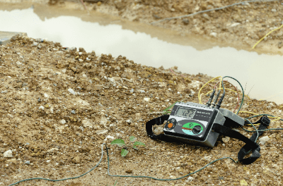
An Earth Resistance Meter is a device that measures the electrical resistance between an electrical device and the earth. It is one of the most familiar devices for electricians and electrical practitioners. Grounding refers to the connection between the earth and electrical equipment.

When an abnormality occurs in electrical equipment, a person touching the equipment may receive an electric shock. By grounding electrical equipment, it is possible to release the electric current to the earth in the event of an abnormality. Secure grounding is very important for the safety of electrical equipment. The state of being securely grounded is called “grounded.”

Uses of Earth Resistance Meters

Earth Resistance Meters are used for grounding work and electrical equipment inspections. Grounding is the process of burying a metal or other electrical conductor deep underground. It is one of the most important works for electricians, and is classified into four types from A to D according to the intended use of the grounding.

The grounding pole for high-voltage equipment is called Class A grounding, which must maintain a resistance of 10 Ω or less, and the grounding pole for low-voltage equipment of 100 to 200 V is called Class D grounding, which is specified as having a resistance of 100 Ω or less.

During grounding work, check the grounding resistance using an Earth Resistance Meter. Electricians and chief electrical engineers use Earth Resistance Meters on a daily basis.

Principle of the Earth Resistance Meters

The measurement principle of the Earth Resistance Meteris Ohm’s law. The Earth Resistance Meter applies an alternating voltage between the pole to be measured and the pole to be compared. After the voltage is applied, the current flowing between the two poles is measured, and the ground resistance is calculated by dividing the current by the applied voltage.

Although the above method can be used to calculate the ground resistance, this method measures the ground resistance of the target pole and the pole to be compared, plus the ground resistance of the two poles. Therefore, a separate grounding pole dedicated for voltage measurement is provided to measure the grounding resistance of the target pole only.

If a DC voltage is used in the Earth Resistance Meter, electrolysis occurs and the current value cannot be determined. Therefore, AC power is often used in Earth Resistance Meters. Since AC power supplies are affected by lead capacitance at higher frequencies, power supplies with a frequency of 1 kHz or lower are used.

How to Use an Earth Resistance Meter

There are three types of Earth Resistance Meters: analog display, digital display, and the method of reading the scale value when the scale needle displays “0”. As an example, the procedure for using an analog display type is shown below.

The Earth Resistance Meter comes with a metal rod called an auxiliary grounding pole, which is embedded in the ground when measuring earth resistance.

  • Step 1: Embed the first auxiliary grounding pole P at a distance of about 10 m from the grounding pole to be measured (hereinafter referred to as “grounding pole E”).
  • Step 2: Place an auxiliary grounding pole C at a distance of about another 10 meters on the straight line extension connecting the grounding pole E and the grounding pole P.
  • Step 3: Connect each grounding pole to each terminal of the Earth Resistance Meter.
  • Step 4: Confirm that the battery capacity is OK and that the voltage between E and P is less than the allowable value.
  • Step 5: Press the measurement button, and the value displayed is the value of the grounding resistance.

The procedure for other Earth Resistance Meters is basically the same as the analog display method, but the “read the scale value when the scale needle shows “0”” method reads the scale value when the scale needle shows “0”. The green, red, and yellow wires attached to the Earth Resistance Meter are used to connect each grounding pole to the terminals on the body of the Earth Resistance Meter.

In addition to these, there are also clamp-type Earth Resistance Meters that measure earth resistance by clamping the ground wire. It is easy to measure because there is no need to bury the auxiliary pole in the ground, but it can be used only in the case of multiple grounding.

Other Information on Earth Resistance Meters

Difference Between an Earth Resistance Meter and an Insulation Resistance Meter

Insulation testers and Earth Resistance Meters differ in measurement items and objects to be measured. An insulation tester measures an electric circuit to check the insulation status, while a grounding tester measures the grounding pole to check the grounding resistance.

The insulation tester applies a DC voltage, while the Earth Resistance Meter applies an AC voltage. Although the appearance and names of the devices themselves are similar, it is important to understand the above-mentioned differences between them in advance.

カテゴリー
category_usa

Network Resistors

What Is a Network Resistor?

A network resistor is a composite component consisting of multiple resistors interconnected. This single component functions as multiple resistors, making it a practical choice in electrical and electronic circuits. Network resistors come in two main types: leaded types, consisting of discrete components connected with jumper wire legs, and surface-mounted types, comprising chip components designed for surface mounting.

Uses of Network Resistors

Network resistors are utilized in situations where multiple resistors of the same value are required within a circuit, such as in boards with various identical circuit configurations. They help in reducing the mounting area and overall board size, thereby enhancing circuit integration. Additionally, network resistors are cost-effective, as purchasing a single network resistor with multiple connected resistors is usually cheaper than buying the same number of individual resistors.

Principle of Network Resistors

Commonly, network resistors consist of multiple resistors connected in parallel. In the leaded type, thick film resistors are arranged in parallel. Each resistor has a common electrode on one side and a lead wire connection on the other, serving as the element terminal. The assembly is insulated with a glass coating and encased in outer resin, forming a unified component.

Some network resistors function as voltage-dividing resistors, with terminals emerging from between two series-connected resistors. For instance, a network resistor with a voltage divider function can halve a 10 V voltage to 5 V using just one element.

Variants with differing resistance values, such as 2x, 4x, and 8x, are also available. These are particularly useful in ladder circuits and similar configurations, significantly enhancing circuit integration while reducing costs.

カテゴリー
category_usa

Proportional Counter

What Is a Proportional Counter?

A proportional counter is a type of radiation detector. It detects radiation by measuring the number of electrons (electric current) produced by the ionization of gas molecules when energetic particles pass through a gas.

Ionization chambers and GM (Geiger-Müller) counters are radiation detectors based on similar principles, but they differ in the magnitude of the voltage applied to measure the current. Ionization chambers operate at lower voltages than proportional counters, while GM counters operate at higher voltages than proportional counters.

Applications of Proportional Counters

Proportional counters detect radiation such as X-rays, α-rays, β-rays, γ-rays, and neutrons and measure radiation counts and energy. Because of their simple structure and relatively easy manufacturing, proportional counters are often used as detectors in academic research and other fields.

Generally, they are used to measure radiation dose in the air, especially for neutron detection and β-ray contamination detection. Proportional counters for X-rays are also sometimes incorporated as detectors in X-ray fluorescence film thickness meters, which are used for non-contact measurement of plating thickness, etc., because of their larger incident window and higher efficiency compared to semiconductor detectors.

Principle of Proportional Counters

The proportional counter is usually a cylindrical aluminum vessel filled with a mixture of inert gases such as argon, helium, or neon, and methane or butane and operated by applying high voltage to wires stretched inside the tube. The cylindrical vessel has an incident window through which radiation enters the tube.

When the incident radiation passes through the gas, the gas along its path is ionized to produce electrons and cations. The electrons produced are called primary electrons. The primary electrons are accelerated by the electric field in the tube and ionize the gas anew, and these ionized electrons cause further ionization, resulting in a phenomenon called gas amplification in which the number of electrons increases explosively. The amplified electrons flow into the wire inside the tube and are detected as an electrical pulse.

Since the number of amplified electrons is proportional to the energy of the incident radiation, this detector is called a proportional counter. The amplification rate of electrons depends on the type of gas and the applied voltage, but if the gas and voltage are known, the energy of the incident radiation can be measured.

An ionization chamber operates on a similar principle to the proportional counter but operates at a lower voltage and therefore does not amplify the gas. Therefore, proportional counters have the advantage of higher sensitivity than ionization chambers. On the other hand, proportional counters have the disadvantage that they cannot measure the number of primary electrons as accurately as an ionization chamber, and their energy resolution is inferior.

カテゴリー
category_usa

High-Frequency Power Supplies

What Is a High Frequency Power Supply?

A high frequency power supply is a power supply that outputs a constant voltage with a frequency ranging from several kHz to several hundred kHz.

Power supply types are classified according to their switching elements, with some using transistors and others using vacuum tubes. The vacuum tube method has been used for a long time and uses a large transmitter tube and transformer, so the size of the power supply is large.

On the other hand, the method using transistors has recently seen the development of inverters that use elements called MOSFETs, and the advantages are smaller size and higher power supply output efficiency. High frequency power supply is mainly used to heat objects using a method called induction heating.

Industrial applications include quenching, ERW pipe welding, thin steel plate heating, plasma generation, and cleaning.

Uses of High Frequency Power Supplies

High frequency power supplies are used to generate eddy currents to heat objects in high frequency induction heating. Specific applications are as follows:

  • Microwave and electromagnetic induction heating
  • Plasma generation
  • Surface modification
  • Cleaning

Used in semiconductor and LCD manufacturing, MEMS manufacturing, solar cell manufacturing, plasma cleaning, steel and forging industries. It is also increasingly used in the new materials industry, food manufacturing, building materials manufacturing, wood drying, medical thermotherapy, electronics, automotive, vinyl fusion, and other industrial fields.

High frequency power supplies for plasma generation excite plasma by means of a high frequency electric field, thereby heating the ions and electrons that form the plasma. By irradiating the surface of polymer materials and other materials, they can be used to select the type of functional group and control the radical species on the surface, which is also used in the development of functional materials.

Principle of High Frequency Power Supplies

To generate a high frequency power supply, the input AC power supply must be converted once to DC, passed through an inverter, and then converted again to AC. First, the AC power supply is converted to DC using bridge diodes.

A bridge diode is an element consisting of six diodes connected in a bridge. By inverting the negative voltage side of the AC power supply, a DC voltage can be output. Next, the DC voltage is converted to a square wave using a switching element, and this square wave is connected to a matching transformer.

The voltage is then converted according to the number of transformer windings, and finally converted to AC power in a resonant circuit.

Types of High Frequency Power Supply

High frequency power supplies (inverters) are classified according to their switching elements.

1. Thyristor Inverter

Thyristors are used as the oscillator element. They are suitable for commercial power supply frequencies up to 10 kHz and high voltages, and have a large element.   

2. Bipolar Transistor Inverter

Suitable for small oscillators 500W to 2kW. The element is small and is used for handy types, etc.

3. IGBT Inverter

GBT stands for “Insulated Gate Bipolar Transistor.” The elements are large and suitable for high-current applications and series resonance circuits. The frequency range is: 10kHz to 50kHz, for high output.

4. MOSFET Inverter

MOSFET stands for “Metal-Oxide-Semiconductor Field Effect Transistor.” It is suitable for high-frequency applications and is smaller than other devices. Frequency range is 100kHz to 400kHz, so it is not suitable for high output power.

5. Vacuum Tubes

Vacuum tubes are suitable for high-frequency applications, self-excited oscillation type with frequencies ranging from 100 kHz to 10 MHz. They use a large transmitter tube and a large transformer, so the equipment becomes larger.

Other Information on High Frequency Power Supply

Types of Power Supply Control

1. Voltage Control
This control method uses thyristors or other elements to suppress DC voltage. It is suitable for quenching because the frequency is fixed and the current penetration depth can be fixed.

The circuit is complex and expensive because of the need for flattening with a power supply capacitor.

2. Current Control
On the oscillator side, the output current value is constant because the frequency is varied by automatically adjusting the load resistance to match the indicated current value. Therefore, the oscillator frequency is always changing.

3. Power Control
The input power value is calculated by multiplying the voltage and current value of the DC section. The output is then controlled with respect to the indicated value.

4. PWM Control
This is a control method found in small oscillators. It is a control method in which the pulse width (duty ratio) is varied while the period remains constant.
カテゴリー
category_usa

Dew Point Hygrometer

What Is a Dew Point Hygrometer?

Dew Point Hygrometers

The dew point is the temperature at which condensation occurs when a gas is cooled. A dew point hygrometer is used to measure the dew point of the gas continuously.

The first application where dew point measurement is needed is in dryers. A low dew point means less moisture in the air, so moisture can be efficiently removed from items that need to be dried.

In the industrial gas industry, a high dew point also means that there is more moisture in the air.

When used outdoors, the low temperatures can lead to condensation and freezing. Therefore, the dew point is always measured with a dew point hygrometer.

Uses of Dew Point Hygrometers

The first use of dew point hygrometers is in dryers. The word “dryer” may bring to mind a machine that dries food at high temperatures, but some foods may deteriorate under high temperatures.

Therefore, it is necessary to dry them at low temperatures, and in doing so, it is essential to expose them to air with a low dew point, so the dew point is constantly measured with a dew point hygrometer.

In other industries, there are also machines that do not like moisture or whose efficiency is reduced by moisture.

When supplying nitrogen or oxygen to such machines, the dew point is always measured with a dew point hygrometer.

Principle of Dew Point Hygrometers

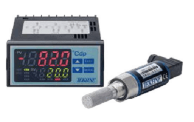
A dew point hygrometer is an instrument that measures the moisture content in the air. The dew point hygrometer can be broadly divided into two types of measurement methods: the capacitance type and the mirror-cooled type.

The capacitance type is easy to measure and is used in portable devices. On the other hand, the mirror-cooled type is highly accurate and can be used for applications requiring high accuracy.

As the name suggests, the capacitance type uses electricity to detect moisture. The capacitance type has a very thin sensor inside, on which a special metal is deposited. When moisture adheres to the sensor, the resistance value changes depending on the amount of moisture. This change in resistance is output from the sensor as the amount of moisture.

As the name implies, the mirror-cooled type uses a mirror. In the mirror-cooled type, the gas whose dew point is to be measured is sprayed onto the mirror surface inside the instrument. Cooling then causes condensation to form on the mirror surface, and heating the mirror surface eliminates the condensation.

The dew point is output by repeating this process to find the best balance. Therefore, highly accurate measurement is possible, but it takes some time.

カテゴリー
category_usa

Linear Gauge

What Is a Linear Gauge?

A linear gauge is a measurement device that determines the displacement of an object. It utilizes optical methods to measure displacement, involving a moving slit attached to the object, two fixed slits, and a machine that converts the slit waveform into a pulse wave. The displacement is interpreted from the number of wave pulses, with accuracy dependent on slit spacing.

Applications of Linear Gauge

Linear gauges are primarily used in machine tool control across various industries, including automotive, home appliances, machinery parts, logistics, and research. Selecting the right gauge involves considering its accuracy, environmental suitability, and mountability.

1. Machine Tools

In machine tools, such as lathe equipment and milling machines, linear gauges measure shaft rotation speeds and the travel of cutters and drills.

2. Load Displacement Measurement

They are used to measure displacement under a constant load, such as in testing the strength of automobile bodies or doors.

Principle of Linear Gauge

Linear gauges function by detecting changes in light patterns caused by the movement of the object.

1. Calculation of Displacement

Displacement is calculated based on the light passing through the moving slit and its variation in relation to the fixed slits.

2. Orientation Calculation

The gauge calculates the direction of movement by observing the phase shifts in the light pattern between the moving and fixed slits, outputting two square wave signals with a 90° phase difference.

Structure of Linear Gauge

A linear gauge comprises a detection part with a light source and slits and a counting section that transforms light waveforms into pulse waves.

1. Detection Part

The detection part includes a light source, two fixed slits, and a moving slit attached to the measured object. The fixed slits are offset to discern the movement direction of the moving slit. The output signal is either 4um or 40um per pitch, depending on the resolution type.

2. Counting Section

The counting section, consisting of a light-receiving element and a counter, multiplies the signal to achieve a measurement resolution of a quarter pitch.

Other Information on Linear Gauge

1. Indication Accuracy

Indication accuracy refers to the measurement error of the linear gauge, calculated over the entire length of the moving slit’s travel.

2. Temperature Effect

Accuracy is affected by temperature. The linear expansion coefficient of the glass scale used in the detection section is considered to calculate indication accuracy at different temperatures.