What Is a Switching Regulator?
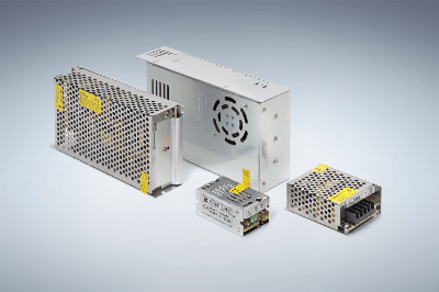 A switching power supply (SMPS) is a power supply that incorporates a highly efficient power conversion circuit called a Switching Regulator.
Electronic devices with ICs and microcontrollers require stable direct current with minimal voltage fluctuation. There are two types of regulated power supplies: linear power supplies and switching regulators, but linear power supplies have been the most common.
In the case of linear power supplies, the circuit is simple. It converts a 100 V AC voltage into a constant AC voltage and rectifies the AC current by utilizing the diode’s property of flowing forward current but not reverse current. It further uses a capacitor to smooth it out. However, this had the disadvantage that it did not allow power supplies to be made smaller or more efficient.
Switching regulators have solved this problem. While linear power supplies convert commercial alternating current to voltage and then rectify it, switching regulators do the exact opposite: they rectify commercial alternating current to DC and then convert it to voltage.
Then, by switching on and off, it is converted into pulse wave AC and fed into a high-frequency transformer, which is the mechanism of switching regulator.
The feature of switching power supplies is that they are smaller and lighter, but their circuits are more complex.
Uses of Switching Regulators
Compared to conventional linear power supplies, switching regulators have much more complex circuits, but they have the advantage of being extremely compact due to the use of ICs for the stabilization circuit.
The large and heavy power transformer (a device that uses electromagnetic induction to convert the height of AC power voltage) is not installed, as in the case of a simple power supply, and this has made it possible to reduce the size and weight.
Because of this compactness and light weight, applications for switching regulators include AC adapters for cell phones. They are also highly compatible with small electronic devices such as PCs and tablets, which are often carried around.
Recently, in order to further promote miniaturization, high-power and high-efficiency GaN devices have been incorporated into switching regulators for AC adapters to realize even smaller AC adapters compared to conventional Si devices.
Principle of Switching Regulators
The principle of switching regulators is the opposite of the conventional linear power supply. Linear power supplies use a transformer to convert commercial current to voltage and then rectify it, whereas switching regulators first rectify commercial alternating current to DC and then convert it to voltage. However, once rectified, voltage conversion cannot be performed using a transformer.
Therefore, in switching regulators, the rectified current is converted into pulse-oriented AC by high-speed switching of semiconductor elements such as transistors and MOS FETs, and then fed into a high-frequency transformer. This increases the number of components and circuits required and makes them more complex, but this complexity is the key to switching regulators.
There are several types of control methods for switching regulators, the most common of which is the PWM (pulse width modulation) method. PWM is a method of stabilizing voltage by adjusting the on-time of the switching on/off cycle, or the width of the pulse wave, so that the area of each pulse is the same. Switching regulators can also be said to increase efficiency because the output can be adjusted by switching on and off.
In addition, since the pulses of switching regulators are high-frequency, ranging from tens to hundreds of kHz, the transformer can be small and lightweight. However, high frequencies increase the loss of the iron core, so a ferrite core is used. This improves power supply efficiency and saves energy.
The ferrite core has a core rod made of a material called ferrite that is attached to the cable so that it wraps the cable. This absorbs the magnetic field generated by the high-frequency noise current flowing through the cable and converts it into heat, thereby reducing noise.
The weak point of switching regulators is the generation of noise due to high-speed switching, which is expected to be reduced by ferrite technology.
Other Information on Switching Regulators
1. Frequency of Switching Regulators
Switching regulators convert the output voltage to a specified voltage value by adjusting the ON/OFF time of the switching operation using semiconductor elements. The frequency of the signal that controls this switching is called switching frequency.
2. Reason Why 24V Voltage Is Often Used
In electrical products that use switching regulators, the output voltage required for the power supply is often 24 VDC. The reason for this is that control circuits require that voltage, although there are various theories.
One theory is that since DC was once often powered by batteries, it was determined by an integral multiple of the 1.5V of a dry cell battery cell. In small devices, 6V, 9V, 12V, etc. are also used, but these are also integer multiples of 1.5.
In the days before PLCs (programmable controllers) replaced control circuits used in factory automation, circuits consisted of electromagnetic relays, and the voltage was used to turn on the relays.
As a remnant of this, 24V is still often used today. There are also other reasons such as the fact that 24 VDC is more resistant to noise environments.
3. Noise in Switching Regulators
Switching regulators use switching elements to turn current on and off at high speed, so it is inevitable that they generate high-frequency noise.
The history of the development of switching regulators has been one of increasing efficiency and at the same time, noise suppression has been a must. Modern switching regulators are equipped with various noise suppression measures.
Switching regulators are themselves a source of noise. Noise is not only added to the output power line, but also becomes electromagnetic waves that affect electronic equipment.
The following methods are available for noise suppression:
- Reflection
Using inductors and capacitors as filters to prevent noise components from being transmitted
- Absorption
Absorbing noise with ferrite cores, etc. and converting it into heat or other energy
- Bypass
Dropping noise to ground with capacitors, etc.
- Shield
Radiated noise components are dropped to the ground with a metal case or absorbed with a ferrite material or other radio wave absorbing material.
4. Detailed Examples of Noise Suppression for Switching Regulators
The most common types of noise are common mode noise and differential noise.
Common mode noise
This is noise that leaks through parasitic capacitance generated between the switching regulator circuit board and the equipment chassis and returns to the power supply side through the GND as a loop path.
Differential Noise
In this case, the noise is current noise from a noise source entering the switching regulator circuit in series with and returning to the power supply side via the power supply line. As the name implies, the direction of each noise current at the positive and negative poles of the power supply is opposite and is also called normal mode noise.
It is called differential noise because the direction of the noise current at the positive and negative poles of the power supply is the same for each.
Generally speaking, common mode noise is the more radiated of the two types of noise, but countermeasures must be taken for both if the allowable noise level is exceeded. The first method is to shorten the cable length of the path or to use stranded cables.
For more serious countermeasures, a noise filter must be added. Choke coils are effective against common-mode noise. A bypass capacitor to ground, called a pass capacitor, is also used. Differential noise suppression is achieved by connecting capacitors between power lines flowing in opposite directions.

 A laser module is a set of devices that produce a
 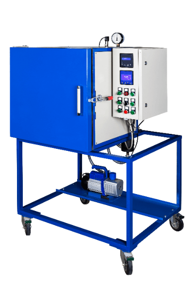 A vacuum furnace is a furnace capable of vacuum heat treatment processing.