What Is a Metering Pump?
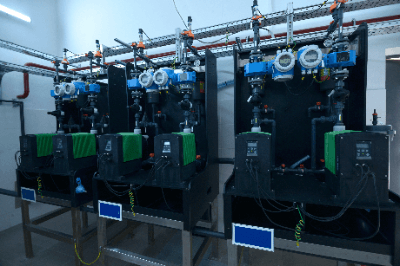
A metering pump is a device that repeatedly pumps a fixed amount of liquid.
It is suitable for accurate dosing of chemicals and other liquids. Metering pumps are constructed of corrosion-resistant materials because they are required to resist corrosion. Generally, electricity or compressed air is used as The driving force.
Uses of Metering Pumps
Metering pumps are used to pump out a certain amount of liquid.
The following are examples of applications for metering pumps:
- In the manufacturing lines of pharmaceuticals and chemical products
- For chemical injection and sterilization in agriculture and livestock industries
- For adding sterilizing chemicals in water purification plants
- During neutralization in wastewater treatment plants
Mainly used in industry as part of the manufacturing process, they are also widely used in infrastructure facilities such as water purification plants and wastewater treatment plants.
Metering pumps in the medical field require highly accurate liquid volume control, as errors can directly affect human lives.
Principle of Metering Pumps
Metering pumps are broadly classified into reciprocating and rotating mechanisms.
The reciprocating mechanism in a metering pump will pump liquid by reciprocating a piston. Liquid can be pumped as much as the volume of the piston. It has the advantage of pumping liquid at high pressure.
The rotary mechanism in a metering pump will pump liquid by rotating an impeller or the like. It is capable of pumping out liquid as much as the volume of the impeller and casing. The structure is simple and it can handle a wide range of liquids.
Types of Metering Pumps
Various types of metering pumps are used.
1. Plunger Pump
A plunger pump is a type of reciprocating pump in which the plunger, a rod-like piston, moves back and forth. It is capable of continuously pumping a fixed volume of liquid at high pressure.
2. Piston Pump
A piston pump is a type of reciprocating pump that pumps liquid through the reciprocating motion of a piston. It is characterized by the use of seals and valves on the piston side for pumping liquid. It can be used under high pressure and it has the advantage of high efficiency.
3. Diaphragm Pump
This is a type of reciprocating pump that pumps liquid using a reciprocating motion of an elastic membrane, such as resin. It is characterized by its seal-less feature and it is widely used for transferring chemical solutions.
It has the disadvantage of pulsation, and flow is generated only when the diaphragm operates. For instantaneous high flow rates, the piping diameter must be enlarged to match the peak flow rate. Pulsation flow can be counteracted by introducing an air chamber or accumulator downstream of the pump or by shifting the phase and installing multiple units in parallel.
The flow rate is adjusted by changing the stroke width and frequency. Drive sources vary, but mainly motor-driven and electromagnetic (solenoid) types are used. The former uses an inverter, and the latter uses electronic control to change the stroke rate.
Ultra-compact diaphragm pumps using piezoelectric elements (piezoelectric elements) are called micropumps. They can handle minute flow rates, such as several µL/min.
4. Screw Pump
This is a type of rotary pump that pumps liquid by rotating a threaded rotor inside the pump. It is characterized by extremely low pulsation.
5. Gear Pump
This is a pump in which two gears mesh with each other and pump liquid only as much as the volume of the gears and casing. When the flow rate is high to some extent, pulsation is minimal. Pulsation appears when the flow rate is reduced and the rotation speed decreases. The flow rate is adjusted by controlling the rotation speed with an inverter.
6. Vane Pump
This is a type of rotary pump that pumps liquid only as much as the volume of the impeller-like vane and casing. The vanes can be installed slightly off-center from the center of the pump.
7. Tube Pump
A tube pump is a pump that continuously pushes liquid in a tube by means of multiple rollers attached to a rotating rotor. It has a simple mechanism with high quantitative performance and it is used for pumping liquid for analytical instruments and adding chemicals.
It is capable of pumping a small amount of chemical solution at a few µL/min. The flow rate is adjusted by controlling the number of roller rotations with an inverter.
8. Syringe Pump
This pump pushes a syringe at a constant speed and can supply minute flow rates with absolutely no pulsation. However, it is a batch process and cannot supply continuously. It is used for medical applications.
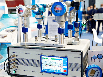 A pressure calibrator is an instrument used in the maintenance of
  Arc welding robots are robots that perform arc welding in place of humans.
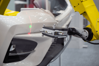 A
A  A humidity sensor is a sensor that measures humidity in the air.