カテゴリー
category_usa

ADCs

What Is an ADC?

Analog-to-Digital Converters

An ADC is a device that converts analog data into digital data.

Most information in the real world is continuous analog data, which must be converted into digital data expressed in terms of 0s and 1s to be processed by a computer. The opposite is called an ADC, which converts digital data to analog data.

ADC is available in various architectures (conversion methods) with different sampling rates and resolutions. Therefore, it is necessary to select the appropriate one according to the purpose.

Uses of ADCs

ADCs are used in numerous applications in our daily lives. Specifically, they are used in digital cameras and audio equipment. They convert analog data such as video and sound into digital data for output.

Various electronic devices need to use analog signals as input information, but the internal processing is done with digital signals. Therefore, ADCs are required. ADCs are installed in devices that handle light, temperature, etc.

High-speed ADCs with high sampling rates are being developed for digital cameras and audio equipment, which require high-speed transmission.

Principle of ADCs

The conversion of analog data into digital data by ADCs is divided into three major stages.

  1. Sampling is performed by periodically cutting out a continuous analog signal.
  2. Approximating the amplitude of the sampled signal to a discrete value is done.
  3. Encoding is performed to represent the approximated signal in binary 0s and 1s. The circuit that performs the encoding is called an encoder.

Sampling rate and resolution are indicators of ADC performance. The sampling rate represents the speed of conversion; the higher the value, the faster the conversion.

Resolution is an indicator of how finely the data can be expressed and is expressed in bits (the number of binary digits in the encoding). The higher the value, the smoother and more accurate the representation.

There is a trade-off between sampling rate and resolution, whereby resolution is sacrificed for high-speed sampling, while a slower sampling rate is required to achieve high resolution.

Other Information on ADCs

1. Resolution of ADCs

The resolution of ADCs are concept of how finely the input analog signal can be quantified. The unit is expressed in bits, where 8-bit data is broken down to the eighth power of 2 and expressed as a number from 0 to 255. In general, the number of bits is often a multiple of 8.

If the analog input is a number from 0 to 2 and the ADCs have an 8-bit resolution, then 2/(2^8-1) = 2/255 = 0.007843. From the above, the minimum resolving power of an 8-bit-ADCs that can input from 0 to 2 is 0.007843. As high-precision ADCs, 32-bit, and 64-bit products are in practical use. 

2. Sampling rate of ADCs

In ADCs, the sampling rate is an important index as well as resolution; the sampling rate of ADCs is how often it samples an analog quantity. This is the speed at which the Analog-to-Digital converters operate.

By the Nyquist Theorem, we know that ADCs require a frequency that is at least twice the frequency of the input analog signal. Therefore, the sampling rate of the ADCs is set to 2.2 times or more than the input analog signal frequency. 

3. Accuracy of ADCs

ADCs are subject to errors. For example, a 16-bit ADCs with an analog input of 0 to 2 has an error of 2/(2^16-1)=0.0000030518. The degree of accuracy at which sampling is required is determined by the above calculation.

It is important to note that the performance of the ADCs does not always directly translate into the performance of the device; input protection circuits, amplifiers, attenuators, etc. are provided before the input terminals of the ADCs, where minute signals are handled.

If the peripheral circuits of the ADCs are not carefully selected, the performance of high-precision ADCs may not be fully demonstrated.

カテゴリー
category_usa

Flow Sensor

What Is a Flow Sensor?

A flow sensor is a measuring instrument that measures the flow rate of a fluid, from gas to liquid.

It is sometimes treated as a flowmeter. Flow rate is the volume or weight of fluid that passes through one cross-section in a unit of time.

There are various types of flow sensors, including analog flow sensors that monitor the fluid flowing in a fluid circuit for abnormalities, and digital flow sensors that are connected to a feedback control mechanism to adjust the gas supply to a certain volume.

Uses of Flow Sensors

Flow sensors are used in the following fields:

1. Hydraulics, Pharmaceutical/Chemical, and Food Industries

Flow sensors are mainly used to control the input of raw materials in manufacturing processes. The volumetric flow sensor is used in these fields.

2. Measurement of Industrial Gases, Fuel Gases, and Exhaust Gases

Flow sensors are used to control the amount of industrial gases, fuel gases, and exhaust gases used in factories. Thermal mass flow meters are the most common type.

3. Drinking Water, Sauces, and Flammable/Explosive Fluids

Food-related and highly hazardous fluids require non-contact measurement that does not touch the fluid For this purpose, electromagnetic flow sensors are used.

4. Industrial Facilities and Water Treatment Facilities

Flow sensors are used for flow control in industrial plants and water treatment facilities. Ultrasonic flow sensors are used especially when adding flow sensors to existing pathways.

5. LNG Plants, Automotive, Chemical, and Pharmaceutical Industries

Flow sensors are used in a variety of manufacturing settings. Coriolis flow sensors are most commonly used.

6. Chemical and Pharmaceutical Industries

Kalman vortex flow sensors are widely used in plants that handle natural gas and water vapor.

Principle of Flow Sensors

Flow sensors employ a variety of measurement formats depending on the nature of the fluid to be measured and the purpose of the measurement. This section describes the principle of differential pressure flow sensors, which are applicable to common fluids such as air and water.

The principle used in differential pressure flow meters is Bernoulli’s theorem. During the flow of a fluid of a certain size, if the flow path is intentionally narrowed, a pressure difference is created due to a pressure drop in the fluid. This pressure difference is applied to Bernoulli’s law to calculate the flow velocity.

There are various types of flow sensors, such as orifice-type and nozzle-type, depending on the mechanism used to narrow the flow path. However, they all share the same principle of measuring the pressure difference between the fluid before and after the narrowing mechanism.

How to Select a Flow Sensor

The appropriate flow sensor depends on the type of fluid to be measured. If you select the wrong flow sensor for a gas or a liquid, you will not only record the wrong flow rate, but also risk a serious accident, particularly if the chosen flow sensor is ill-suited for measuring the flow rate of a hazardous or flammable substance. Therefore, it is important to start by carefully examining the nature of the substance to be measured.

In addition, flow sensors generally cannot measure a wide range at once. If the expected flow rate is determined in advance, it is best to select a flow sensor with high accuracy for that range.

Other Information on Flow Sensors

1. About Clamp-on Type Flow Sensor

Clamp-on means that the instrument is mounted outside the piping through which the fluid to be measured flows. Clamp-on flow sensors include ultrasonic flow meters and ultrasonic flow sensors.

If the object to be measured is a fluid or other material that can be measured by ultrasonic waves, it can be used as a measurement device. Ultrasonic flowmeters include the propagation time difference method and the frequency measurement method using the Doppler method. The advantage of ultrasonic flowmeters is that they can be installed without removing or cutting piping, thus reducing the cost of installation.

Another advantage is that maintenance after installation is greatly improved and pressure loss in the piping is eliminated. Conversely, demerits include the need for a long straight pipe section since the meter is installed outside of the piping, the fact that the diameter of the piping is also a factor, and the fact that measurement cannot be performed if the fluid to be measured contains many solids or bubbles.

2. Air Flowmeter

Air flowmeters include clamp-on flowmeters and screw-connection flowmeters. The screw-connection type eliminates the need for an intuitive part, and the measurement device is compact and space-saving.

Conventional air flowmeters have used thermal mass flowmeters if the gas to be measured is a compressible fluid. There are several measurement methods for thermal mass flowmeters. In the capillary type, a flow element with ohmmeter is installed inside the tube and a heater is wound around the outside of the tube, and temperature sensors on both sides of the heater measure the flow balance.

However, thermal mass flowmeters are vulnerable to contamination and are not good in low-pressure environments, making them unsuitable for facilities with large amounts of oil mist. Currently, the flow sensor type is the most common type of thermal mass flowmeter.

This type is composed of a semiconductor flow sensor and can be used in low-pressure environments with a wide measurement range and without concern for contamination.

カテゴリー
category_usa

Linear Motor

What Is a Linear Motor?

Linear Motors

A linear motor is an electric motor that produces motion in a straight line, unlike conventional motors that generate rotational motion. It operates on the principle of magnetism, utilizing the attraction and repulsion of magnets or the Lorentz force to create propulsive force. This design allows for direct linear movement, eliminating the need for complex mechanisms required by traditional motors to convert rotational motion to linear motion.

Uses of Linear Motors

Linear motors are widely used in various applications, from linear motor cars, such as the linear bullet train which achieves high speeds with minimal frictional loss thanks to magnetic repulsion, to industrial equipment requiring precision, such as machine tools and semiconductor manufacturing equipment. They are also found in consumer products like electric curtains, shaving machines, camera autofocus systems, and even in the food industry, exemplified by revolving sushi restaurants.

Principle of Linear Motors

The operation of linear motors relies on magnetic attraction, repulsion, or the Lorentz force, akin to conventional motors but designed to produce linear instead of rotational motion. There are several types of linear motors, including linear induction motors, linear synchronous motors, linear DC motors, and linear stepping motors, each based on different principles of operation.

1. Linear Induction Motor

Utilizes electromagnetic induction for propulsion, driving an electromagnet across a magnet-aligned NS-SN using electric current. This type is preferred for industrial applications requiring high precision.

2. Linear Synchronous Motor

Operates on magnetic attraction and repulsion, with motion generated by altering the magnetic poles of fixed magnets in sync with movable electromagnets. This method is highly efficient, making it suitable for linear motor cars to reduce power consumption, with magnetic levitation trains using superconducting magnets to further minimize energy loss.

3. Other Methods

Linear DC motors and linear stepping motors are employed in actuators and precision control of optical equipment, respectively. Linear piezoelectric motors, though less efficient, offer high precision control and are used in precision machinery.

Other Information on Linear Motors

1. Speed and Precision of Linear Motors

Linear motors offer significant benefits in speed and precision, eliminating the need for reduction mechanisms and allowing for accurate positioning. They can operate over long distances and can be configured with multiple units working in unison. Despite challenges in control, thrust, and maintenance, advancements are continually made, increasing their application in precision tools like grinders and lathes, and contributing to environmental preservation efforts.

2. Cooling of Superconductive Linear Motors

Superconductive linear motors, essential for magnetic levitation trains, utilize superconducting magnets that operate at low temperatures with zero electrical resistance, thereby creating a powerful magnetic field without energy loss. Advances in cooling technologies, moving away from liquid helium to materials like bismuth-based copper oxide, allow for higher operational temperatures and more efficient, compact cooling systems, paving the way for the development of high-temperature superconducting magnets.

カテゴリー
category_usa

Power Inverter

What Is a Power Inverter?

A power inverter is a device that transforms input current into alternating current (AC). It can convert both direct current (DC) and AC; in the case of AC, it first converts the input to DC, then back to AC with adjusted voltage and frequency. To distinguish it from power inverter circuits, which are part of its structure, it’s sometimes referred to as a power inverter device.

Uses of Power Inverters

Power inverters are commonly used in electrical products featuring motors, as they control motor rotation. Air conditioners, for example, utilize power inverters in their compressors to regulate motor speed, enabling precise temperature control beyond the simple on/off method. This not only improves functionality but also significantly enhances energy efficiency, which is why modern air conditioners are typically equipped with power inverters.

Principle of Power Inverters

The core components of a power inverter include a converter circuit, a capacitor, and an inverter circuit. The process involves converting AC to DC through a converter circuit, using diodes for rectification. The rectified current is stored in a capacitor and then shaped through charging and discharging to create a pseudo-DC current. This current is fed into an inverter circuit, where pulse width modulation (PWM) generates pulse waves of varying widths, combining to produce a pseudo-sine wave. This allows for the free manipulation of output voltage and frequency, characterizing voltage-type and current-type power inverters.

Other Information on Power Inverters

1. Merits and Demerits of Power Inverter Control

Advantages
Power inverters are primarily adopted for their energy-saving benefits, allowing for precise motor speed adjustments and enhancing the accuracy of temperature control in devices like air conditioners and oil consoles, compared to traditional on/off temperature regulation methods.

Disadvantages
However, power inverters can be costly, and their capacitors, being consumable components, require periodic replacement. The decision to use power inverters should be made after weighing these factors carefully.

2. Causes of Power Inverter Breakdown

Long-term use of power inverters may lead to overcurrent and overvoltage issues, often due to the lifespan of their electrolytic capacitors. These capacitors are sensitive to temperature; a 10°C increase can halve their lifespan. Particularly in devices like air conditioners used extensively in summer, capacitors can wear out quickly, leading to failure. Signs such as motor vibration or noise may indicate the need for early replacement, as capacitor deterioration can also result in swelling or leakage.

カテゴリー
category_usa

Aluminum Electrolytic Capacitor

What Is an Aluminum Electrolytic Capacitor?

Aluminum Electrolytic Capacitors
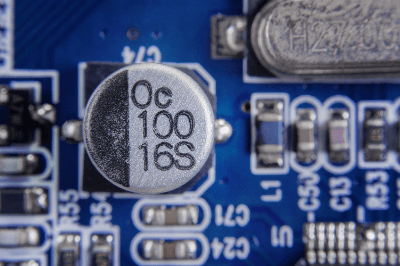
Aluminum electrolytic capacitors are small capacitors with high capacitance that use aluminum oxide as the dielectric.

Wet type capacitors use an electrolyte as the cathode, but dry type capacitors using solids such as conductive polymers with improved performance are also available. Because of their low price and high versatility, they are used in many products with electronic circuit boards, such as home appliances and personal computers.

Uses of Aluminum Electrolytic Capacitors

Aluminum electrolytic capacitors are used in a wide variety of products with electronic substrates in a wide range of fields, such as automobiles, home appliances, and industrial equipment, because they are smaller, have a larger capacity, and are less expensive than other capacitors.

Specific applications are as follows:

  • Automotive Field
    Engine control units, advanced driver assistance systems, air bag controls, car stereos, car navigation systems
  • Home Appliances
    Televisions, recorders, digital cameras, audio equipment, refrigerators, washing machines, air conditioners, microwave ovens, lighting fixtures, personal computers, TV game consoles
  • Industrial Equipment Field
    Various manufacturing equipment, power conditioners for renewable energy

When used as power conditioners for renewable energy, many of them use 10 to 100 aluminum electrolytic capacitors. Due to their high versatility, the performance requirements for aluminum electrolytic capacitors are increasing year by year.

Principle of Aluminum Electrolytic Capacitors

Aluminum electrolytic capacitors use thin aluminum foil for the anode and cathode and aluminum oxide for the dielectric. Aluminum oxide is formed on the surface of the aluminum foil by an electrochemical oxidation process (chemical conversion).

The surface of the aluminum foil is made uneven by an etching process to increase the surface area. The capacitance of a capacitor is expressed by the following equation, which is proportional to the surface area of the dielectric and inversely proportional to its thickness.

Capacitance C = ε × S/d 
ε: Dielectric permittivity of dielectric S: Surface area of dielectric d: Thickness of dielectric

A disadvantage of aluminum oxide coatings is that they generate more leakage current than other capacitors because of the minute current flow when voltage is applied. The internal cathode of a wet aluminum electrolytic capacitor uses an electrolytic solution, which can leak in the event of a failure.

Another drawback is that the electrolyte may decrease due to electrolyte leakage or evaporation, resulting in low durability. Dry aluminum electrolytic capacitors, on the other hand, do not evaporate because conductive polymers are used for the internal cathode, and are more durable than wet capacitors.

Other Information on Aluminum Electrolytic Capacitors

1. Life Span of Aluminum Electrolytic Capacitors

Among electronic components, wet aluminum electrolytic capacitors are known to have a particularly short life span: while LSIs are required to operate for tens of thousands of hours, a typical aluminum electrolytic capacitor has a life span of 2,000 hours at 85°C and a highly reliable one of 5,000 hours at 105°C.

One of the reasons for the short life expectancy is the structure of aluminum electrolytic capacitors, in which the electrolyte impregnated in the insulating paper gradually leaks out from the rubber sealing section over time. When the electrolyte leaks out, the capacitance decreases and ESR (equivalent series resistance) will increase.

The life of an aluminum electrolytic capacitor is said to follow Arrhenius’ law (chemical reaction formula based on thermal energy) when the temperature is below the maximum operating temperature, and the life is approximately doubled when the temperature is 10°C lower. Therefore, an aluminum electrolytic capacitor with a life of 2,000 hours at 85°C will last 4,000 hours if used at 75°C, and 8,000 hours at 65°C.

Compared to other capacitors, aluminum electrolytic capacitors have a large ESR, and when a large current flows during operation, the inside of the capacitor generates heat. This heat generation causes the temperature of the capacitor to rise, which further promotes electrolyte leakage and shortens the life of the capacitor.

2. Polarity Indication on Aluminum Electrolytic Capacitors

Polarized capacitors are always marked with some kind of indication so that the polarity can be easily checked.

  • Vertical Electrolytic Capacitor
    Generally, there is a line on the negative pole side below the body. Also, the lead wire of the negative electrode is shortened.
  • Surface Mount Type Electrolytic Capacitor
    Capacitance and withstand voltage are indicated on the top surface of the electrolytic capacitor, and there is a colored mark in one corner. The electrode below this mark is the negative electrode.
  • Axial Lead Type Capacitor
    The line with an arrow indicates the lead of the negative electrode. The electrolytic capacitor body has a recess; the side with this recess is the positive electrode.

It is extremely important to check the polarity indication because if the polarity is incorrectly marked, the capacitor may not only malfunction but may also catch fire.

カテゴリー
category_usa

Strain Gauge

What Is a Strain Gauges?

Strain Gauges

A Strain gauge is a device that measures the strain of an object. They have also been used in pressure gauges and force gauges because they can measure strain and calculate pressure, load, etc.

Uses of Strain Gauges

Strain Gauges are used to measure the strain of products whose strength is directly affected by strain, to measure loads in production plants, and to measure the degree of deformation of molds and other components. However, care must be taken to ensure that the strain cages are installed in the correct orientation, otherwise, measurement errors will occur.

Specific examples of use include the following.

  • Measurement of strength and strain of printed circuit boards
  • Monitoring and measuring the load on press equipment

Principles and Types of Strain Gauges

1. Principle of Strain Gauges

Strain cages are used by attaching them to the object to be measured, which is then strained along with the object to be measured, resulting in a change in the internal electrical resistance. The strain is calculated by measuring the amount of change in the electrical current.

2. Types of Strain Gauges

There is a great variety of strain gauge types. The most widely used are foil strain gauges, wire strain gauges, and semiconductor strain gauges.

Other features of strain gauges include those suitable for low and high-temperature environments, those capable of measuring finer strains, and those made of materials suitable for various materials to be measured.

Structure of Strain Gauges

The structure of  “foil strain gauges” and “semiconductor strain gauges” are described below.

1. Foil Strain Gauges

The structure of foil strain gauges, the most popular type of strain gauges, consists of a metal foil attached in a zigzag pattern on an insulator base, with two wires coming out of the metal foil. These two wires are connected to a circuit called a Hoinston bridge circuit.

The Hoinston bridge circuit is a circuit in which three resistors of known resistance and four strain gauges are arranged in a bridge configuration, and the resistance of the strain gauges can be measured by measuring the potential difference between the center of the resistors and the strain gauges.

When the object to be measured to which the strain gauges are attached is distorted, the foil of the strain gauges attached expands or contracts, resulting in a change in the value of electrical resistance, and the amount of change in resistance is obtained from the potential difference in the Hoisington bridge circuit. Since strain gauges have a gauge factor, which is an intrinsic value of the amount of change in resistance to strain, it is possible to calculate the strain of the object to be measured from the gauge factor and the amount of change in resistance.

2. Semiconductor Strain Gauges

Semiconductor strain gauges are strain gauges that utilize a semiconductor in the foil portion of a foil strain gauge. They utilize the property that the electrical resistivity of a semiconductor changes when stress acts on the semiconductor.

Other Information on Strain Gauges

1. How to apply Strain Gauges

The accuracy of strain measurement using strain gauges strongly depends on the method of gauge installation (adhesion in most cases). Therefore, it must be very careful when attaching strain gauges to a measurement object. The first step is to clean the surface of the measurement target to which the gauge is to be attached.

It is best to use an oil-based detergent to remove oil thoroughly. Failure to do so will allow oil to penetrate deeper into the material when the surface is ground or polished during application. After cleaning, lift the gauge with tweezers and carefully adhere it to the surface to be measured.

At this time, it is important to ensure that all empty bubbles between the surface and the gauge are pushed out so that they can be affixed. In this state, wait a few minutes for the adhesive to harden. After a few minutes have elapsed, finally wrap the entire surface with insulation tape to protect it from damage, and the pasting is complete.

2. Drawbacks of Strain Gauges and how to solve them

The advantage of strain gauges is that they can easily measure strain simply by bonding them to the object to be measured. In reality, however, there are many complex factors involved that make measurement more difficult. For example, the problem of stress is one of them.

Strain changes due to the material’s interaction between externally applied forces and internal stresses. Therefore, analysis of strain in two or three directions requires using “rosette strain gauges,” which are a combination of multiple gauges.

In addition, depending on the coefficient of thermal expansion of the material constituting the measurement object, the strain may be determined to have occurred even if there is no actual strain. To prevent this, it is necessary to match the material of the gauge with the material to be measured.

In strain measurement with strain gauges, the best one must be selected from among many types of gauges based on a good understanding of their physical or mechanical characteristics. 

3. Strain Gauges and Temperature Compensation

The major factors affecting strain gauges bonded to the measurement object are strain caused by external forces and temperature change. When temperature changes occur, the strain gauges are affected by the difference in the coefficient of linear expansion between the measurement object and the strain gauges, and by the change in resistance of the strain gauges due to temperature.

The measurement of strain as if it is caused by temperature change is called apparent strain. The use of self-temperature compensating strain gauges is the most effective countermeasure against apparent strain. Self-temperature compensating strain gauges are strain gauges in which the temperature coefficient of resistance of the strain gauges is adjusted to suit the measurement object to minimize the amount of apparent strain due to temperature.

Selecting the appropriate strain gauges for the measurement object is the best choice, but it may leave some errors. In some cases, they have nonlinear characteristics. In most cases, this error is noted on the data sheet of the strain gauges, and if more precise measurement is required, a compensation calculation can be made to account for the error calculated from the datasheet.

4. Strain Gauges and Creep Compensation

Creep is a phenomenon in which strain increases with time when a constant load is applied under certain temperature conditions. The creep phenomenon is the natural enemy of strain gauges, and if it occurs, it may directly lead to measurement errors.

In most cases, the creep phenomenon of strain gauges is caused by the base material, grid shape, and adhesive. Therefore, a common method is to cancel the effects of creep phenomena on each other by using a strain generator in the opposite phase of the creep caused by these factors as the material creep and attaching strain gauges to it.

The important point is the combination of materials. If the creep phenomena are in opposite phases, but their absolute values are very different, they cannot be canceled, and the effect will be in one direction. Note that, depending on the material, creep phenomena are more pronounced at higher temperatures in most cases. Please remember that the higher the stress applied to the strain gauges, the shorter the time to rupture (life), considering the increase in strain due to the creep phenomenon.

カテゴリー
category_usa

Positive Temperature Coefficient (PTC) Thermistor

What Is a Positive Temperature Coefficient (PTC) Thermistor?

A PTC thermistor is an electronic component whose resistance value increases sharply at a certain temperature.

PTC stands for positive temperature coefficient, meaning that there is a positive correlation between temperature and resistance. Thermistor is derived from the term “Thermal Sensitive Resistor”. A thermistor is a component that can measure temperature from the difference in electrical resistance when a resistive element is brought into contact with the object to be measured. It is characterized by the use of a metal oxide semiconductor as the resistive element.

An overcurrent protection device using a positive temperature coefficient (PTC) thermistor is also called a resettable fuse. Tube and blade fuses use alloy elements that need to be replaced once they blow, so the principle is different from that of common fuses.

When an excessive current flows in a circuit, a resettable fuse limits the current value by causing the positive temperature coefficient (PTC) thermistor to become hotter and its resistance to increase. When the cause of the excessive current is removed, the positive temperature coefficient (PTC) thermistor decreases and its resistance becomes lower. Therefore, it is used as a resettable fuse.

Uses of Positive Temperature Coefficient (PTC) Thermistors

PTC positive temperature coefficients (PTC) thermistors are used in electronic circuit boards and a wide range of other applications, from home appliances to industrial applications. The following are examples of positive temperature coefficient (PTC) thermistor applications:

  • Overcurrent and overload protection for smartphones, etc.
  • Overload protection for small motors
  • Electric carpets and heaters
  • Overload protection for motors and power semiconductors

PTC positive temperature coefficient (PTC) thermistors have a low resistance value when the temperature is low, but when overheated due to excessive current, the resistance value increases rapidly. This mechanism allows them to be used for overcurrent protection in electrical circuits. Circuits in which PTC thermistors are used include heater circuits and electronic communication devices.

Protection against overheating must also be considered when using power semiconductors and motors. This is where positive temperature coefficients (PTC) thermistors are used. To protect against overheating, a positive temperature coefficient (PTC) thermistor is used by physically thermally coupling the PTC thermistor to a heat sink or motor winding for heat removal.

The positive temperature coefficient (PTC) thermistor is used to detect overheating by increasing its resistance, and the circuit is configured to stop operation or shut off the power supply.

Principle of Positive Temperature Coefficient (PTC) Thermistors

PTC thermistors have three major characteristics:

1. Resistance Temperature Characteristics

The resistance value is almost constant from room temperature to the Curie point (temperature at which the resistance value is about twice that of room temperature), and increases rapidly after the Curie point. This property allows the device to detect overheating of an electronic circuit quickly and limits the circuit current, thereby preventing failure of electronic components.

2. Static Characteristics (Voltage-Current Characteristics)

Until the Curie point is exceeded, the current rises in proportion to the rise in voltage. Once the Curie point is exceeded, the resistance of the thermistor itself increases, and the current value decreases. In other words, a constant power is maintained. The voltage-current characteristic is characterized by a mountain-like graph.

3. Dynamic Characteristics (Current-Time Characteristics)

The current-time characteristic of a PTC thermistor is characterized by the fact that the current value decreases over time. This characteristic allows a large current to flow immediately after the power is turned on, and is used for motor startup and other applications.

Types of Positive Temperature Coefficient (PTC) Thermistors

PTC thermistors can be classified into two types: polymer-based and ceramic-based.

1. Polymer Type

Polymer-based PTC thermistors are manufactured by mixing conductive particles with polymer materials, such as polyethylene. Carbon black and nickel are used as conductive particles.

They are also known by the acronym PPTC. Resettable fuses are also called poly switches, but the name is derived from the polymer. The positive temperature coefficient (PTC) thermistor is used only for overcurrent protection.

2. Ceramic-Based

PTC thermistors are positive temperature coefficient (PTC) thermistors made of ceramic with a small amount of rare earth elements added to barium titanate. Curie temperature can be adjusted by adjusting the amount and type of additives. They are used not only for overcurrent protection but also for demagnetization circuits and self-regulating heating elements.

カテゴリー
category_usa

Negative Temperature Coefficient (NTC) Thermistor

What Is a Negative Temperature Coefficient (NTC) Thermistor?

Negative Temperature Coefficient (NTC) Thermistors
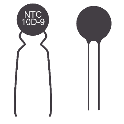
Negative temperature coefficient (NTC) thermistors are electronic components whose resistance decreases as the temperature increases.

NTC stands for negative temperature coefficient, meaning that there is a negative correlation between temperature and resistance. Thermistor is derived from “thermal sensitive resistor”. A thermistor is a component that can measure temperature from the difference in electrical resistance when a resistive element is brought into contact with the object to be measured. It is characterized by the use of a metal oxide semiconductor as the resistive element.

Negative temperature coefficient (NTC) thermistors are the most versatile of all thermistors because the material is inexpensive and easy to process. They are high-precision thermistors because their resistance value changes even with minute changes in temperature. They are widely used in familiar home appliances and industrial equipment.

They are used as temperature sensors by detecting differences in resistance. Lead type, chip type, disk type, and thin-film type are available.

Uses of Negative Temperature Coefficient (NTC) Thermistors

Negative temperature coefficient (NTC) thermistors are used in a wide range of applications, from industrial applications to home appliances, due to their inexpensive characteristics. They are mainly used as temperature sensors.

  • Internal temperature detection in smartphones
  • Inrush current reduction in electronic circuit boards
  • Temperature measurement in electronic thermometers
  • Motor temperature monitoring in vacuum cleaners
  • Temperature detection in refrigerators

1. Application to Smartphones

Smartphones use heat-sensitive components and components that lose accuracy due to heat, so it is important to prevent heat buildup. Therefore, the negative temperature coefficient (NTC) thermistor detects internal temperature changes and conveys the information to the IC. In addition to measuring room temperature, NTC thermistors are also used as temperature protection elements to protect circuits from overheating in order to stabilize circuits and prevent failures.

2. Inrush Current Reduction

In electrical and electronic equipment, a large current exceeding the steady-state current value may temporarily flow at power-on. This current is called inrush current. The reason for inrush current may be the initial charging of a large-capacity capacitor.

Negative temperature coefficient (NTC) thermistors are sometimes used to suppress inrush current at power-on by taking advantage of their high resistance value at low temperatures. As the temperature of the thermistor rises due to current loading, the resistance value decreases and power decreases as well.

Since the resistance value decreases as the temperature rises due to energization, power loss can be reduced compared with the use of fixed resistors. Therefore, negative temperature coefficient (NTC) thermistors are used as ICLs (Inrush Current Limiters) to protect circuits of electrical and electronic equipment by easily and effectively limiting inrush currents.

3. Temperature Measurement Circuits

Negative temperature coefficient (NTC) thermistors are widely used in temperature measurement circuits. Since this component detects temperature change by resistance change, it is often used in combination with other resistors. The most commonly used circuit configuration is to use a thermistor connected to a constant voltage source via a pull-up or pull-down resistor.

Principle of Negative Temperature Coefficient (NTC) Thermistors

The main component of the negative temperature coefficient (NTC) thermistor is ceramics, which is a semiconducting ceramics made by mixing and sintering oxides of manganese, nickel, cobalt, etc., with electrodes attached. There are N-type and P-type semiconductors depending on the doping substance.

Normally, the transfer rate of free electrons and holes decreases as the temperature rises. However, in negative temperature coefficient (NTC) thermistors, electrons in the valence band are transferred to the conductor by thermal energy, and the rate of increase of free electrons and holes in the conductor is greater than the rate of increase of free electrons and holes, resulting in lower resistance. Negative temperature coefficient (NTC) thermistors are characterized by a gradual decrease in resistance.

To make negative temperature coefficient (NTC) thermistors, raw oxides are mixed to make a uniform mixture and temporarily baked at 800°C to 1,000°C. They are then pulverized and the grains are sized. After crushing them, the grain size is increased to a size suitable for molding, and then they are formed into their final shape and fired at 1,300-1,500°C. Finally, electrodes are formed and the product is finished by coating with epoxy resin.

How to Select Negative Temperature Coefficient (NTC) Thermistors

Negative temperature coefficient (NTC) thermistors are selected according to application, dimensions, B constant, and resistance value. The application is the use for which negative temperature coefficient (NTC) thermistors are used. These include automotive and electronic board mounting applications. Select a thermistor according to its dimensions and the situation in which it is to be mounted.

The larger the B constant, will create a greater change in resistance with temperature. Therefore, products with a large B constant have high sensitivity, while those with a small B constant have low sensitivity.

The resistance value is the normal resistance value at room temperature (25°C). Generally, a product with a small resistance value should be selected for low-temperature environments, while a product with a large resistance value should be selected for high- temperature environments.

カテゴリー
category_usa

Printed Circuit Board (PCB) Inspection System

What Is a PCB Inspection System?

A PCB is a device that inspects for problems such as misalignment, disconnection, shorts, cracks, floating parts, and soldering of components mounted on the board. This inspection is called board visual inspection.

In addition to functional testing of electronic circuit boards to ensure correct operation, board visual inspection (also called board inspection or mounting inspection) inspects whether each electronic component is mounted in the correct position without defects.

Electronic board inspection is called AOI (Automated Optical Inspection).

If there are no problems in the board visual inspection, a functional inspection is performed to ensure that the product actually works as designed.

Function testers are used for this functional inspection.

Uses of PCB Inspection Systems

Until now, board visual inspections have been performed visually by human eyes.

However, with visual inspections, the criteria for acceptance or rejection may differ depending on the subjectivity of the inspector.

In addition, the more inspection items are required, the more personnel are needed, resulting in higher labor costs.

In addition, electronic circuit boards are generally manufactured in a factory on a production line. Visual inspections have a limited processing capacity, and this limits the speed of the production line.

PCB visual inspection systems are introduced to increase efficiency and reduce costs by automating inspections that were previously performed by human labor.

Principle of PCB Inspection Systems

Since PCBs use a machine to perform what was originally done visually, it requires “eyes” to see the appearance and “brains” to judge whether it is good or bad, just like a human being.

Therefore, the PCBs consist of a camera as the “eye” and a computer equipped with image processing software as the “brain”.

The most common defect in board visual inspection is soldering defects.

The PCBs determine whether soldering is good or bad by using a straight line connecting the boundary of the solder adhesion surface and the electronic component adhesion surface as a threshold value and whether or not it exceeds this value.

Since the threshold value varies depending on the shape of the component and other factors, such as the electronic board, it is necessary to input all kinds of threshold data into the image processing software.

In recent years, to alleviate this complication, three-dimensional imaging with multiple cameras and the use of X-ray cameras have made it possible to detect defects that cannot be detected with ordinary cameras.

False Alarm Rate

The false alarm rate is one of the most important indicators for inspection equipment.

Although it is as old as 2009, here is an article describing the false alarm rate data from a survey on the current status of product inspections conducted by the Japan Institute of Electronics Packaging to Japanese manufacturers of printed circuit boards and electronic devices.

Inspection of Board Mounting by PCB Inspection Systems

Electronic boards manufactured by manufacturers can have various types of defects. For this reason, various types of PCB inspection systems are used to identify boards with defects. There are various types of board defects, the most common of which are listed below.

1. Component Defects

  • Component Not Mounted: Component is not mounted in the correct position
  • Component misalignment: A component is removed from the pad and mounted out of the correct position.
  • Component floating: Only one side of the component is soldered and the other side stands up.

2. Solder Defects

  • Disconnection: No solder is applied
  • Short: Excessive amount of solder adhering to adjacent pads
  • Void: A defect caused by air bubbles during soldering
  • Poor wetting: Solder is clean but electrical contact is incomplete
  • Solder ball: A ball-shaped lump of solder
  • Bridging: Solder is connected between adjacent IC pins
  • Cracks: Cracks on the surface of the solder
  • Imo-solder: Solder does not bond well and the solder is bumpy like a potato

What Is AOI?

AOI stands for Automated Optical Inspection. It is an automated visual inspection in which an electronic board is photographed by a camera or other means to inspect for serious defects and quality defects. Because optical inspection is non-contact and non-destructive, it has been introduced in many board manufacturing processes. Methods used in automated optical inspection include camera-based imaging, laser reflection, and X-ray transmission.

Visual inspections used to be performed by human operators, but they are now widely used for a number of reasons, including the fact that it is no longer easy to distinguish between small, integrated boards due to the increasing integration of circuits, cost reductions and productivity increases due to labor and manpower savings, and quality value enhancement by reducing human error.

カテゴリー
category_usa

Print Inspection System

What Is a Print Inspection System

A print inspection system is a device that inspects for errors or problems in the printing of dates in manufacturing processes in the food and medical industries.

In recent years, consumers have become increasingly aware of the need for safety and security, and errors in the labeling of product expiration dates in the food and medical industries can lead to major problems. Any printing error can result in not only the loss of money and time associated with product recalls, but also the loss of customer trust.

Therefore, a print inspection system that prevents errors caused by human factors is in high demand in the manufacturing field. The introduction of a print inspection system enables stable inspections with high accuracy and consistent standards and also guarantees records through image storage.

Uses of Print Inspection Systems

Print inspection systems are often used on production lines to inspect the presence or absence of print, as well as any missing or incorrect print, on the expiration date, factory-specific symbols, lot numbers, and other items printed on products and packages.

The system can inspect the printing in areas that are difficult to identify manually or that require time for visual inspection, such as the backside of products. Images used for inspection can also be saved, which helps reduce risk by anticipating problems after shipment.

The print inspection systems can be linked with a mechanism that ejects only NG products after inspection. By interlocking with the ejection mechanism, NG products can be ejected while the line is still in operation. The main mechanisms that can be introduced include an air jet ejection mechanism from an air outlet and an arm mechanism to eject NG products with pinpoint accuracy.

Principle of Print Inspection Systems

Print inspection systems consist of a camera that captures images of the printed surface, an analyzer that inspects the captured images, a monitor that displays the results and settings, and storage for storing the images.

A fixed digital camera captures images of the printed surface as it flows from the production line. The captured images are subjected to image analysis and inspected for problems. In production, it is important not only to detect errors with high accuracy but also to avoid detecting errors excessively.

With the development of image analysis technology, there are print inspection systems with many features that can detect not only characters in the printed area but also other problems such as the presence of smudges. In addition, there are also print inspection systems available that can be linked to a printing machine, which is expected to improve inspection efficiency and further automate the process.

Other Information on Print Inspection Systems

Advantages of Print Inspection Systems

1. Reduction of Inspectors and Elimination of Errors
By installing print inspection systems, the work can be done without the inspectors’ manual labor required for print inspections. In addition, when inspections are conducted manually, inspection errors can occur. To maintain work efficiency and quality assurance for a long time, print inspection systems are very important.

2. Highly Accurate Print Inspection
Some models of print inspection devices are equipped with a printer interlocking function, which automatically synchronizes item switching, calendars, etc., eliminating omissions and errors in settings. In addition, print inspectors can identify misprints, missing prints, and missing prints with high accuracy, thereby controlling excessive error reactions and preventing unnecessary lost items, thereby ensuring reliable inspection while maintaining productivity.

3. Print Images Can Be Saved to Prevent Recurrence
By saving the inspection images of the print inspection machine, it is possible to keep an inspection history at the time of shipment. If a problem occurs after the product has been shipped, the cause of the problem cannot be identified because the date and time of the print inspection and the condition of the product at the time of shipment cannot be confirmed if the inspection images are not saved. By storing all inspection images, it is possible to investigate the cause of the problem and prevent recurrence, which has the advantage of leading to a more stable supply of food and medical products.