カテゴリー
category_usa

Stand-Up Bags

What Is a Stand-Up Bag?

Stand-up bags, also called freestanding bags, are so-called hand-cut plastic bags with a bottom gusset.

The bags are made of thicker material, and as the name “stand” implies, the bags themselves can stand on their own and be managed when filled with contents.

Because they are polyethylene bags, they are highly transparent, making it possible to see the contents at a glance without having to open the bag.

Some bags are equipped with zippers, making them even more functional.

Uses of Stand-Up Bags

Stand-up bags are often used for food applications.

They are often used for displaying produce such as mini-tomatoes and strawberries, and for selling detergents and cosmetics.

Zippered bags are also often used to put cookies and other snacks, tea leaves, and other items that move frequently in and out of the bags.

Some types are also used to hold liquids such as health food jellies, juices, and medicines.

Principle of Stand-Up Bags

Stand-up bags stand on their own because they have a gusset at the bottom.

Stand-up bags with a zipper for opening have a notch at the top of the pack, which makes it easy for consumers to open the pack by hand at the top of the zipper.

In addition, the bag is cut at the top of the zipper, allowing the bag to be resealed with the zipper after opening.

Other Types of Stand-Up Bags

1. Flat Bags

There is another similar type of bag called a flat bag. It is flat and there are no gussets on the sides, so it does not stand up on its own and is not suitable for thick raw materials.

However, these bags have the advantage of being less bulky.

2. Gusset Bags

Gusset bags are flat bags with gussets on the sides. They can hold thicker raw materials than flat bags.

3. Three-Side-Seal Bags

Three-side-seal bags are made by heat-sealing the top and sides of the bag at the time of production.

4. Square Bottom Bags

Square bottom bags have a gusseted, square bottom and can hold a large amount of raw materials.

カテゴリー
category_usa

Stand-Up Pouches

What Is a Stand-Up Pouch?

A stand-up pouch is a pouch that can stand on its own and has folds at the bottom. The technology was introduced in France in the 1960s and gradually spread throughout the 1980s.

The characteristics of this type of pouch are that it is excellent for displaying products, and it can also be used to create attractive displays. In addition, the notched opening, zipper, or stopper can be selected according to the contents to be filled. Also, depending on the way the contents are to be used, it is used for a variety of applications, including food and toiletry products. In recent years, with the increase in environmental awareness, they are also used for refillable products.

Uses of Stand-Up Pouches

Stand-up pouches are currently used in a wide range of products, including seasonings, miso, soft drinks, soups, pouch foods, and dressings.

The first commercial products were developed for use in packaging processed marine products and processed agricultural products that had previously been packed in cans or bottles. Later, as technology advanced, it became possible to add various properties such as moisture resistance, transparency, suitability for vacuum packaging, low-temperature resistance, impact resistance, abrasion resistance, gas barrier property, light shielding property, and oil resistance, making it suitable for a wide variety of applications. Those with stoppers are also used for jelly beverages and refillable edible oils.

Characteristics of Stand-Up Pouches

Stand-up pouches are made up of two parts, depending on the pouch production method. One consists of a two-piece body and bottom, and the other consists of a single piece. The materials used include biaxially oriented polyester film, cellophane, and aluminum film.

Stand-up pouches use a barrier material to prevent deterioration of the contents, but the barrier material has been gradually changing with technological advances. When first introduced to Japan, PVDC coated film and AL foil were commonly used. However, in the 1970s, EVOH resin and other barrier materials became available, and the development of laminated films that could be retorted using high-performance urethane adhesives and other materials led to the popularization of stand-up pouches as packaging materials.

Pouches for beverages became popular as a new application after they revised food sanitation laws to allow the use of polyester and NY as materials. In the case of beverage use, the emphasis is on flavor matching with the packaging material.

Later, dessert pouches were commercialized using food preservation techniques that combine low PH and high sugar content of the food itself, boil sterilization, and food deterioration prevention techniques such as packaging materials incorporating barrier materials such as EVOH in laminated films. In addition, the use of O-NY, which is easily torn in one direction, in laminated films to improve tear capability, has evolved into a commercial product.

Other recent improvements include the use of single-site polyethylene to increase material strength to prevent pinholes and ruptures, and the emergence of transparent vapor deposited films with silica or alumina barrier materials deposited on O-PET or O-NY.

カテゴリー
category_usa

Studs

What Is a Stud?

Studs

Studs are metal fittings or clasps. The most common method is to insert them, but depending on the use of the stud, the tip of the needle may be crushed.

Other types of studs include rivets, stud bolts, and spike tires. Tacks are also used as decorative studs on furniture, bags, and clothing. For example, iron tacks are used for furniture.

Uses of Studs

Studs are mainly used to secure paper or metal. However, the name stud is used for a wide range of industrial products and components, and the industries and fields in which they are used vary widely. Accordingly, studs come in a wide variety of materials, from metals to plastics.

For example, rivets are among studs, and familiar ones are used to fasten car seats, sheet metal parts, and shutter assemblies.

On the other hand, studs are also used for what are called decorative studs, and in this field, they are used not for fixing things but for decoration. For example, it can be processed to look like an antique, so it is often used as a decoration on residential doors.

Studs are also incorporated into spiked tires, where they are used as non-slip metal studs.

Principle of Studs

Studs are used for a wide range of applications, and the construction of studs varies.

For example, drawing studs can be fixed to walls and objects mainly by simply pushing them into the area from the stud to the head of the shade shape. inserted, very little force is required. The same principle applies to decorative tacks.

Rivets, on the other hand, are generally fastened using a tool such as a hand riveter. There are various types of rivets, and some rivets are fixed by crushing the part of the rivet that is to be pressed into the rivet. Base materials that are difficult to be crushed by hand can be easily fixed by using tools.

Buttons utilized on clothes can also be classified as studs; round buttons sewn on Y-shirts do not fall into the stud category. Some decorated buttons, however, have separate upper and lower parts, and the upper pin portion and the lower receiver portion fit together to form a decorative button.

Thus, studs are used in other fields because they are relatively inexpensive to produce and there are many available.

カテゴリー
category_usa

Scale Inhibitors

What Is a Scale Inhibitor?

Scale Inhibitors, also known as Scale Removers, are an agent that removes water-insoluble stains that have accumulated in transmission and drainage facilities, equipment, and piping.

Scale is a crystallized substance that forms when minerals such as silica, magnesium, and calcium dissolved in groundwater become insoluble in water due to oxidation caused by contact with air or changes in pressure and temperature.

Once crystallized and adhered inside piping equipment, it is extremely difficult to remove, resulting in problems during drainage.

Uses of Scale Inhibitors

When scale clogs the piping of a factory manufacturing site or a boiler in a hot spring, the pressure required for sending and draining water increases. Water circulation slows, production capacity and thermal efficiency decrease, and operating and administrative costs increase.

To remove scale, which is one of the causes of equipment failure related to pumping and draining, removers tailored to various scale components are required.

Other applications include the removal of scaling that forms on mirrors and automobile surfaces.

Principle of Scale Inhibitors

Calcium in groundwater is dissolved in the form of calcium bicarbonate in a high-pressure environment along with carbon dioxide.

As it emerges from the ground to the surface, the pressure drops, and carbon dioxide is released from the groundwater, causing the calcium bicarbonate to precipitate out as calcium carbonate, which is insoluble in water.

Since calcium-based scales can be dissolved under acidic conditions, a pH adjuster such as hydrochloric acid or an oxygen scavenger is used as a remover.

Calcium and magnesium combine with silicon dioxide dissolved in water, and when concentrated in a heat exchanger, magnesium silicate and calcium silicate precipitate and adhere to the surface, forming a scale.

Silica scale is made of silicon, a constituent of glass, and is difficult to remove even with acidic detergents.

カテゴリー
category_usa

Screwless Terminal Block

What Is a Screwless Terminal Block?

Screwless Terminal Blocks

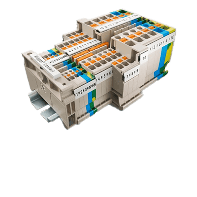
Screwless terminal blocks are a method of securing wiring without the use of screws.

This design significantly reduces the time and effort required for wiring work and at the same time improves the quality of signal transmission. It also greatly improves long-term reliability because it reduces the risk of contact failures due to loose screws.

Especially for hardware engineers and purchasing managers, it is worth seriously considering the use of screwless terminal blocks as an option for new projects and upgrades, as they can be expected to increase production efficiency, enhance maintainability, and even reduce overall costs.

In light of the above, screwless terminal blocks are gaining attention in many industries as a connection solution for modern electronic technology due to their superior characteristics and advantages.

Uses of Screwless Terminal Blocks

Screwless terminal blocks are increasingly being used in a variety of industries and applications as a screwless signal and power connection technology. Here we examine their main applications in detail.

1. Distribution Boards and Switchboards

Distribution boards and switchboards are central devices for power distribution and control. Screwless terminal blocks are extremely useful in these installations because they require solid connections and long-term reliability. They improve safety and maintainability by reducing the risk of loose screws and poor contact.

2. Semiconductor Manufacturing Equipment

In semiconductor manufacturing processes, which require precision and advanced technology, reliable electrical connections are essential. Screwless terminal blocks are ideal for quick and reliable wiring while maintaining signal accuracy and quality.

3. Machine Tools

Machine tools often operate in harsh environments with vibration and heat, requiring highly reliable connection technology. Screwless terminal blocks can maintain stable connections even under such conditions.

4. Storage Batteries

Screwless terminal blocks are increasingly being used to connect storage batteries. This technology is suitable for applications involving high currents and rapid charging and discharging, which require secure connections and high durability.

5. Photovoltaic/Solar Power Generation Equipment

Photovoltaic and solar power generation equipment is sensitive to environmental influences and requires long-term reliability and ease of maintenance. Screwless terminal blocks are the ideal choice to meet these requirements.

Principle of Screwless Terminal Blocks

1. Screwless Terminal Block Spring

The springs set into screwless terminal blocks are often made of stainless steel, and the conductive parts are electrolytic copper or tin plated, making them as durable as or more durable than screw-type terminal blocks over long periods of use. The clamping force of screwless terminal blocks is based on spring force, so they do not require periodic retightening as screw-type terminal blocks do.

The spring force set inside the terminal block secures the wire, and the larger the diameter of the wire, the stronger the clamping force. Therefore, even when using cables of different diameters on the same terminal block, the wire is not easily loosened and can be secured without damaging the wire.

2. Screwless Terminal Block Fixing Method

To secure a wire that has been stripped of its sheath, use a flat-blade screwdriver or a dedicated knob to reduce the force exerted by the spring to hold the wire in place, and insert the wire all the way to the back of the connection port. When removing an electric wire, use a flat-blade screwdriver or a dedicated knob to weaken the spring-loaded restraining force and pull the wire out of the connection port.

Types of Screwless Terminal Blocks

Screwless terminal blocks are widely used in many industries for their convenience and reliability. Various types of screwless terminal blocks are designed and manufactured to suit different uses and applications.

1. For Panel Mounting

Screwless terminal blocks for panel mounting are designed for direct mounting on the external panel of equipment and facilities. This allows for easy access and maintenance.

Primary applications include large equipment, facilities, and electrical wiring termination connection points.

2. For Board Mounting

Screwless terminal blocks for board mounting are designed for direct mounting on electronic boards. This allows them to be used in applications requiring compact design and high integration.

Primary applications include wiring terminations in electronic devices and PCBs, connections between modules, and signal transfer points.

3. For Relaying

Screwless terminal blocks for relaying are used to easily connect and relay two or more electrical circuits. They are characterized by multifunctionality and modular design. In many cases, they are compatible with existing wiring systems.

Primary applications include connecting and branching between cables and extending or modifying electrical circuits.

カテゴリー
category_usa

Screwfeeder

What Is a Screwfeeder?

Screwfeeders

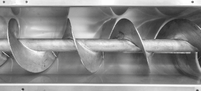
A screwfeeder is a machine that uses screw-shaped blades to feed supplies at a constant speed.

It consists of a spiral-shaped section called a flight, and supplies are fed as the flight rotates. The target objects are often powders, and the machine is used to feed a variety of materials, such as livestock feed.

With liquids, the flow rate can be controlled by opening and closing valves, but with powders, the conveying speed must be changed. In addition, changing the speed of a conveyor or other equipment at only one point may cause shelf fishing or spurting. A feeder is a device that prevents such problems and controls the feed rate.

There are various types of feeders, such as electromagnetic feeders, table feeders, etc., in addition to screwfeeders. They are used according to the required performance, such as the particle size and strength of the powder or grain to be fed, the processing volume, and the fixed-quantity feeding capability. Screwfeeders have relatively high quantitative feeding performance.

Uses of Screwfeeders

Screwfeeders are used in a variety of applications for the purpose of conveying powders.

A typical application is feed feeding in the livestock industry, where they are used to automatically feed livestock and birds on poultry farms. It is possible to supply the appropriate amount of feed according to the condition of the livestock and the time of day. Automatic feeding reduces the burden on keepers and contributes to more efficient breeding management.

They are also used at construction sites. They are used to automatically feed building materials such as concrete and cement. Screwfeeders can feed building materials at a constant speed, contributing to improved work efficiency.

They are also used for feeding raw materials in factories. They are particularly effective for automatically feeding powdered raw materials. It can feed raw materials at a constant speed, supporting stable operation of the production line.

Principle of Screwfeeders

Screwfeeders consist of spiral-shaped sections called flights, which feed material as they rotate.

Screwfeeders can control the delivery of supplies. Supply is controlled by adjusting the rotation speed, the shape of the flights, and the tilt angle of the container. Rotation speed can be controlled by employing inverters, for example.

In addition, plates called baffles may be placed between flights to control the flow of supplies. Baffles are used to control the flow of supplies and achieve uniform feeding.

Structure of a Screwfeeder

It consists of a spiral-shaped flight called a screw attached to a cylindrical container. The flights are attached to the inside of the cylindrical container and the rotation of the flights allows supplies to be fed out of the container. Flights are available in left-handed and right-handed products, selected according to the direction in which supplies are to be sent out.

Screws are available not only in vane type but also in ribbon type where the shaft itself is helical. The number of shafts also varies, including single and double shafts. Generally, these are designed according to the characteristics of the powder or grain to be conveyed.

How to Select a Screw Feeder

In screwfeeders, the driving force of conveying is the friction between the screw and the powder/pellets. Therefore, there is a risk of wear and shape breakage of the powder/pellets. To avoid this, appropriate selection of wear-resistant treatment of the screw and shape of the blades is necessary. It is not suitable for conveying coarse particles that are prone to breakage.

Selection should also be based on the properties of the material. Screwfeeders of appropriate materials must be selected according to the properties of the materials used. For example, when handling corrosive substances, it is necessary to select a screwfeeder made of highly corrosion-resistant stainless steel or similar material.

After considering the above, output capacity should be selected. The output of a screwfeeder affects the rate at which materials can be fed. The output represents the amount of material that can be fed per hour and is expressed in units such as L/h or kg/h.

Other Information on Screw Feeders

Location of Screwfeeder

Screwfeeders are generally installed at the bottom of an inverted conical powder storage container called a hopper, and the powder is pushed out and discharged by the rotation of a screw. Since the powder is pushed by the screw, it can be transported even if the container is inclined upward to some extent.

Another feature of this system is that the powder is sealed inside the screw and the hopper in the front stage, allowing interprocess conveying with pressure differences such as atmospheric pressure and vacuum. Screwfeeders with high sealing performance are used in pneumatic conveying, where the powder is carried by the airflow in the piping.

カテゴリー
category_usa

Jack Screw

What Is a Jack Screw ?

A jack screw is a screw-type jack that utilizes a screw screw.

A jack is a mechanism that can raise and lower heavy objects with little force, and the principle of the screw is used for the raising and lowering motion. Other types of jacks besides jack screws include hydraulic and other types of jacks.

In addition to lifting and lowering heavy objects, jack screws can also be used for moving, rotating, and positioning heavy objects. The jack screws are generally driven manually or by a motor, and are used for inspection and repair of vehicles and ships, as well as on construction sites and in factories.

They may also be used in place of hydraulic presses because of their extremely high output relative to input.

Uses of Jack Screws

Jack screws are used in steel material manufacturing sites, metal processing equipment, automotive parts manufacturing equipment, liquid crystal display and semiconductor washing machines, and substrate conveyors. Screw jacks are incorporated into large equipment, etc., from the equipment design stage.

Our familiar example is a large lift for vehicle inspection in an automobile repair shop. At construction sites, jack screws are sometimes used for height adjustment during the temporary assembly process before welding steel materials.

Principle of Jack Screws

The principle of the jack screw is based on the principle of the screw. Screws are used to convert rotational motion into linear motion for lifting and lowering. A reduction gear with a worm gear is used to drive the jack screw.

The worm refers to the input shaft, and the worm shaft has a spiral-shaped gear. A worm wheel is mounted on the output side to receive the rotation of the worm, and the worm wheel rotates in accordance with the rotation of the worm.

In this image, the worm is the male thread and the worm wheel is the female thread. When the male screw is turned, the screw is tightened with more force than the force of the male screw. The worm reduction gear converts this strong tightening force directly into high-torque rotational force.

Types of Jack Screws

There are two main types of jack screws, depending on the shape of the screw. There are two main types of screw jacks depending on the screw shape: trapezoidal screw type and ball screw type.

Just as a jack screw that has been tightened cannot be pulled out even if it is pulled as it is, a jack screw will not easily fall apart even if a load is applied to it. However, the stability of holding the position under load differs between the trapezoidal screw type and the ball screw type.

1. Trapezoidal Screw Type

The trapezoidal screw type has a self-locking function, so there is no need to worry about reversal (loosening of the jack) no matter where the screw is stopped. Trapezoidal jack screws do not require a separate brake mechanism.

2. Ball Screw Type

Ball screw jacks do not have a self-locking function and require a separate brake (e.g., a magnetic brake). However, the ball screw type can be raised and lowered more efficiently than the trapezoidal screw type, resulting in higher work efficiency and lower power costs.

How to Select a Jack Screw

Jack screws are both versatile and functional, and can be used in a wide variety of ways, depending on your ideas. However, care must be taken when selecting a jack screw for use as part of a large piece of equipment. In particular, if jack screws are not selected based on accurate design regarding “input,” they may be damaged.

Other Information on Jack Screws

Bevel Jacks

Jack screws use worm gears to convert rotational motion to lifting and lowering motion, but there are also bevel jacks that use bevel gears. Bevel gears are also called bevel gears, and have a shape of a cone with gears engraved on it.

In general, the difference between worm gears and bevel gears is the reduction ratio obtained and the transmission efficiency of the gears. The gear ratio of bevel gears is about 1~10, while worm gears can reduce the speed up to 100. The advantage of a worm gear is that a large reduction ratio allows a large lifting force to be obtained even with a small motor.

However, the transmission efficiency of worm gears is lower than that of bevel gears. Note that if the reduction ratio is large and the transmission efficiency of the gears is low, a longer lifting and lowering time is required, and more power is needed to operate the motor in the same time.

カテゴリー
category_usa

Welding Rods

What Is a Welding Rod?

Welding Rods are metal rods used in applications for detecting the position of objects.

They are an important material with electrical conductivity and durability, and are used in a variety of industrial fields due to their advanced functionality and precision. It is commonly used in water treatment facilities, in water storage tanks, water purification plants, and sewage treatment facilities.

It detects fluctuations in water levels. This enables appropriate water supply and drainage control, contributing to improved facility efficiency and safety.

Uses for Welding Rods

Welding Rods capable of detecting water level position are widely used in various industrial fields due to their high reliability and accuracy.

1. Water Treatment Facilities

Accurate monitoring of water levels is important in water treatment facilities. Welding Rods are used in water storage tanks, water treatment plants, and sewage treatment facilities to detect water level fluctuations. They enable appropriate water supply and drainage control, contributing to improved facility efficiency and safety.

2. Water Supply Facilities

Welding Rods are also used to detect water levels in water supply facilities. For example, in water towers and water storage tanks, Welding Rods measure the height of the water level and can be used for water volume control and water supply planning.

Welding Rods are also incorporated into water supply systems in homes and buildings to control water supply based on accurate water level information.

3. Agriculture and Irrigation

Water level monitoring and control is important in agricultural and irrigation systems. Welding Rods are used in agricultural water tanks and irrigation channels to provide accurate water level information. This enables optimization of crop watering rates and irrigation schedules, resulting in more efficient use of water resources.

4. Aquaculture

In the aquaculture industry, it is important to manage the growing environment for fish and shellfish. Welding Rods are incorporated into aquaculture ponds and tanks to monitor and control water levels. By appropriately adjusting the aquaculture environment in response to water level fluctuations, water quality and temperature stability can be ensured and the growing environment can be optimized.

5. Hydropower Generation

Water level control of dams and reservoirs is essential for hydropower plants. Welding Rods detect fluctuations in water levels and provide feedback to the controller to ensure stable power generation and safety.

Principle of Welding Rods

Two or more Welding Rods of different lengths are fixed to the tank. A weak voltage is applied between Welding Rods, and the level is detected when a conductive object comes in contact with them. In most cases, three sets of switch relays, holders, and Welding Rods are used as a set when used in tanks.

The holder holds the electrode rod in place, and after detecting the level with the Welding Rod, the switch relay applies voltage to the Welding Rod while outputting a contact point. Welding Rods are constructed with a device called a “floatless switch”.

The switch relay supplies a weak voltage, less than 30V, and the output is controlled by contact between Welding Rods. The floatless switch has contacts that turn ON when the Welding Rod is immersed at high liquid level and turn OFF when the Welding Rod leaves the liquid at low liquid level. These contacts control the pump operation and shutdown to keep the tank water level within a certain range.

A set of Welding Rods consists of four rods: one for grounding, one for water reduction, one for condensate, and one for full water. Taking the case for controlling the drain pump as an example, it can also be used for controlling the water supply pump by replacing the electrodes for reducing water and condensing water.

1. For Grounding

The ground is the longest Welding Rod and is installed near the bottom of the receiving water tank. It is always in contact with water during operation and is energized, making it the reference for all Welding Rods. It is also called “common electrode”.

2. For Water Reduction

The second longest Welding Rod detects when the water level in the receiving tank has dropped enough to cause problems such as the possibility of the pump idling. It is installed slightly above the pump suction port.

3. For Condensate

These are shorter Welding Rods than those for water reduction. The Welding Rod for water reduction detects that the water level has dropped and that there is enough water to operate the pump again after the pump has been shut down.

4. For Full Water

The shortest Welding Rod detects when the receiving water tank is full. It is installed to prevent full water in the event that other devices that detect full water fail. It is installed above the normal water level for full water detection.

Most Welding Rod products are made of metal and are exposed to liquid, which may cause them to stop working properly due to corrosion. In addition, due to the level detection principle, they are not suitable for detecting insulating objects and cannot be used for insulating oil, etc.

How to Select Welding Rods

When selecting Welding Rods, the length, diameter, and durability should be taken into consideration, depending on the intended use.

Even if the description of the material properties of Welding Rods states that they are “sufficiently corrosion resistant” or “corrosion resistant,” this does not mean that they are completely free from corrosion.

カテゴリー
category_usa

Tool Changers

What Is a Tool Changer?

Tool Changers

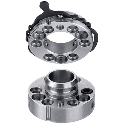
A tool changer is a tool changing mechanism and system used to add tool changing functions to articulated robots and processing machines (machining centers, etc.).

The tool changer is a mechanism and system used to add a tool changing function to an articulated robot or a machining center.

Some tool changers are equipped with an air blow function to remove dust from the tool clamping area in addition to tool loading and unloading. Some tool changers can supply compressed air, water, or electrical signals to the tool.

Uses of Tool Changers

In the past, tool changers were mostly used to change tools on processing machines, but as the introduction of articulated robots increases, tool changers for articulated robots are becoming more common.

Tool changers are used on machining centers to perform various machining operations automatically without the need for human tool change. The tool changer automatically performs tool change, tool height measurement, and runout measurement. This reduces the need for human operators to change tools, check tool height and runout after tool change, and furthermore, by automating parts loading and unloading, it is possible to fully automate the parts machining process.

In articulated robots, this tool changer is generally used to change the hand at the end of the robot. Robot hands have various functions such as gripping by air chuck, rotation by motor, and vacuum suction. Therefore, for articulated robots, tools are available that can be supplied with compressed air, water, vacuum, or electrical signals. By using a tool changer, a single robot can perform multiple tasks, thus helping to improve the efficiency of the use of articulated robots.

Principle of Tool Changer

There are various types of tool changers, but most of them use compressed air to clamp or pull up the tool.

For machining tools, an air cylinder is mainly used to hold the tool in place by pulling up the knob on the tool’s mounting section. Many of the tool mounting parts are tapered (BT and other standards are available), and contact with the taper maintains repeatability of the tool position.

In addition, the tool stocker, together with the tool stocker, is called an ATC (auto tool changer) in machining centers and is treated as a single system. There are different types of stockers, such as disk type and chain-driven type.

For articulated robots, each company has its own clamping mechanism driven by compressed air, often using cams. Fluid supply parts, such as compressed air, water, and vacuum, use seals such as O-rings to prevent leakage. Contact probes are used for electrical signals.

Robot hands are designed by automatic machinery manufacturers to suit their applications, and stockers and other parts are manufactured accordingly, so few are sold as standard products.

カテゴリー
category_usa

Centrifugal Concentrators

What Is a Centrifugal Concentrator?

A centrifugal concentrator is generally a decompression concentration and drying device that combines a centrifuge and a vacuum dryer.

While centrifugal force suppresses sudden boiling, the boiling point is lowered by depressurization, and the heat of vaporization is supplemented by heating to evaporate the solvent and concentrate the target sample.

In addition to being used for the analysis of trace samples, this equipment is also being introduced into the concentration process, which has a significant impact on sludge treatment systems in light of the worsening deposition of sewage sludge. Since it can be operated continuously and almost unattended, it is expected to become more widely used in the future.

Applications of Centrifugal Concentrators

Because centrifugal force prevents solvent from boiling or foaming, sample loss can be minimized, making it suitable for concentrating samples for trace analysis.

They are used, for example, to concentrate DNA, RNA, peptides, and other applications that require concentration and drying.

On the other hand, centrifugal thickeners are also increasingly being used in sewage sludge treatment due to their ease of operation, automatic operation, and maintenance.

Principle of Centrifugal Concentrators

Centrifugal concentrators use the “three states of matter” to concentrate samples. Specifically, the process of solid ⇔ liquid ⇔ gas is concentrated by low-temperature drying under reduced pressure.

First, the boiling point of the sample (solvent) is lowered by reducing the pressure applied to the sample. At the same time, heating accelerates the volatilization of the solvent and prevents the freezing of the solvent that occurs during depressurization.

The overall system consists of a centrifugal concentrator, cooling trap, and vacuum pump. The vacuum pump reduces the pressure in the centrifugal concentrator to concentrate the sample. The cooling trap then condenses and collects the vaporized solvent.

The centrifugal thickener for sludge concentration concentrates excess sludge by centrifugal force. The outer and inner cylinders rotate around a sludge feed pipe while maintaining a constant difference in rotation. Sludge is continuously fed from the sludge feed pipe into the outer drum, and centrifugal force causes the solids in the sludge to settle and accumulate on the inner wall of the outer drum. The sludge is then discharged out as concentrated sludge by the action of a screw installed in the inner drum.

Sludge Concentration by Centrifugal Thickener

Among sewage sludge, sludge in the first sedimentation tank settles easily and can be concentrated by gravity sedimentation, but sludge in the final sedimentation tank (especially excess sludge) does not settle well, so it is not easy to concentrate the sludge by gravity sedimentation. Therefore, it is difficult to concentrate sludge by gravity settling. Mechanical concentration methods include atmospheric pressure floating thickeners and belt-type filtration thickeners, and centrifugal thickeners are one of the mechanical concentration methods.

Sludge is first pumped to the centrifugal thickener and supplied. The structure of the centrifugal thickener is largely divided into an outer bowl and an inner bowl. Before the sludge is introduced into the centrifugal thickener, flocculants are added. By mixing the added flocculant, the sludge mixed with the flocculant is discharged into the end of the bowl. The outer bowl rotates at high speed, and the sludge is subjected to the centrifugal force of 800-1200 G, which initiates sedimentation separation due to the difference in specific gravity between water and solids.

The centrifugal force causes the feed sludge to settle and separate faster than gravity settling. The settled and separated concentrated sludge is transported to the concentrated sludge outlet by a screw conveyor attached to the inner bowl, and the separated liquid is transported to the separation liquid outlet by the flow.

Thus, sludge with a feed sludge concentration of 0.6-0.8% is concentrated and discharged as 4-6% concentrated sludge.

Differential Velocity of Centrifugal Thickeners

The structure of the centrifuge is largely divided into an outer bowl and an inner bowl.

The supplied sludge is fed into the bowls, where it is subjected to centrifugal force, stuck to the outer bowl, sedimented, and separated. The supernatant is discharged as a separated liquid, and the sedimented material as concentrated sludge. The outer bowl and inner bowl of the centrifuge do not rotate at the same speed but rather have a rotational difference of about 3 to 8 revolutions, with the inner bowl, to which the screw conveyor is attached, rotating slightly slower. This difference in the rotation is called “differential speed.” This difference in the rotation is the force that transports the concentrated sludge to the discharge outlet by the screw conveyor.