カテゴリー
category_usa

AC Cables

What Is an AC Cable?

AC cables are cables used to supply AC power.

Generally, cables are not distinguished according to whether the power source is AC or DC. However, the cables of AC adapters that convert commercial power sources to DC power sources may be referred to as AC cables on the AC side because the cable type and connectors differ depending on the power source.

In addition to AC cables, they are sometimes referred to as AC cords or power cords.

Uses of AC Cables

AC cables are mainly used to supply AC power to AC adapters.

The following are examples of uses for AC cables:

  • For supplying power to PCs and displays
  • For supplying power to home-use game machines
  • For supplying power to power tools
  • For supplying power to servers and switching hubs

AC cables are most commonly used for OA equipment. However, they may also be used for household games and power tools.

Principle of AC Cables

AC cables, like other cables, consist of a core wire, insulation coating, and connector plug.

1. Core Wire

The core wire is the metal part that serves as the pathway for electricity. The material used is copper, which has high electrical conductivity. It is generally made up of multiple thin strands of twisted wires.

2. Insulation Coating

The insulation sheath is the insulating portion that insulates the cable core wire. Synthetic resins such as nylon and vinyl are used. The type of insulation sheath determines the performance of the cable, such as heat resistance and weather resistance.

3. Connector Plug

Connector plugs are used to connect OA equipment and power supplies. 

How to Select AC Cables

Points to consider when selecting AC cables include allowable current, plug shape, and cable length.

1. Allowable Current

Allowable current is generally selected in accordance with the capacity of the AC adapter. The allowable current of general outlet cables is 15A, but AC cables with allowable current of 7A or 12A are also available.

2. Plug Shape

The plug shape should be selected according to the connected device and the power outlet. Since the type of power supply and plug shape often differ from those in Japan, use a dedicated conversion adapter.

3. Cable Length

Select an appropriate cable length according to the situation in which it will be used. For laptops, etc., select short AC cables, as long cables can be cumbersome to handle. Longer cables are best for applications where you want to keep electronic devices away from electrical outlets.

Other Information on AC Cables

1. Specified Electrical Appliances and Materials

Specified electrical appliances and materials include cables and extension cables, and most AC cables are also specified electrical appliances and materials. Most AC cables are designated as specified electrical appliances and materials, mainly those that may cause harm to people, such as those that directly conduct electric current.

2. Electrical Appliances Other Than Specified Electrical Appliances

Electrical appliances other than specified electrical appliances and materials include remote control relays and flexible conduits, which are electrical appliances that pose little risk of harm to humans. Electrical appliances and materials marked with PSE in a circle are certified as “Electrical appliances and materials other than specified electrical appliances and materials”.

3. AC Cables and AC Adapters

The AC adapter to which the AC cables are connected converts AC power supplied from a household outlet into DC power. They are classified into two types according to their internal structure: “transformer type” and “switching type.”

In general, the switching type tends to have higher conversion efficiency and generates less heat, and most AC adapters for PCs are of the switching type. However, the switching type has the disadvantage of having more components and a shorter service life than the transformer type.

Transformer-type AC adapters are designed to rectify and rectify AC power that has been stepped down by a direct transformer to direct current. Since a transformer is built in, heat is constantly generated, and the structure is simple and robust, although the conversion efficiency is not good.

Some electrical products are made on the assumption that they are powered by either transformer-type or switching-type power supplies, and the use of an AC adapter of the wrong type may lead to malfunctions.

カテゴリー
category_usa

X-Ray Fluorescence (XRF) Analyzers

What Is an X-Ray Fluorescence (XRF) Analyzer?

X Ray Fluorescence (XRF) Analyzers

X-Ray Fluorescence (XRF) Analyzer is a device that analyzes the content of an element by its X-ray fluorescence spectrum when an object is irradiated with X-rays.

X-Ray Fluorescence (XRF) Analyzers are used for qualitative and quantitative analysis of substances, and are utilized as a method of analyzing the composition of substances because they can be examined in a short time without destroying the sample.

X-Ray Fluorescence (XRF) Analyzer is a highly reliable inspection device because it can measure both solids and liquids and has relatively high sensitivity as a method of qualitative analysis.

Uses of X-Ray Fluorescence (XRF) Analyzer

X-Ray Fluorescence (XRF) Analyzers can perform qualitative and quantitative analysis of samples, both solid and liquid, in a nondestructive manner. They are especially used to determine the presence and content of toxic metals in alloy materials and soil.

For example, X-ray analysis is effective in examining the composition of materials of unknown composition, such as rocks and meteorites. Recently, printed wiring is being made halogen-free from the standpoint of environmental and safety preservation, and X-Ray Fluorescence (XRF) Analyzer is being used to assure this. Other applications include the qualitative and quantitative determination of hazardous chemical substances, and testing for substances specified by the RoHS Directive. Portable instruments that can be easily transported are also available, and their applications are expanding.

Principle of X-Ray Fluorescence (XRF) Analyzer

Figure 1. (a) Generation of X-ray fluorescence (b) Structure of the X-ray analyser

Figure 1. (a) Generation of X-ray fluorescence (b) Structure of the X-ray analyser

X-Ray Fluorescence (XRF) Analyzers measure the wavelength (or energy) and intensity of fluorescent X-rays emitted when an object is irradiated with X-rays.

When a material is irradiated with X-rays, its atoms absorb energy and are excited, emitting X-rays fluorescence. Since the wavelength (or energy) of X-ray fluorescence is unique to each element, it is possible to identify the type of substance from the wavelength of the detected X-ray fluorescence spectrum and to quantify it from its intensity.

X-Ray Fluorescence (XRF) Analyzer consists of an X-ray source that generates X-rays, a sample chamber that holds the sample, and a detection unit that spectra and detects the generated X-rays.

In the X-ray source, electron beams generated by applying high voltage are irradiated to a target such as tungsten to generate X-rays. The generated X-rays are irradiated to the upper or lower surface of the sample. At this time, the atmosphere in the sample chamber may be selected from atmosphere, nitrogen, vacuum, and other atmospheres.

X-Ray Fluorescence (XRF) Analyzers equipped with a sample observation mode allow the user to select the irradiation position while observing the sample. Elemental X-rays emitted from the sample are detected by the detector for qualitative analysis. In quantitative analysis, the intensity of the X-ray fluorescence is measured and the content rate is determined using a calibration curve or the fundamental parameter method (FP method).

There are two types of X-Ray Fluorescence (XRF) Analyzer spectroscopy and detection methods: wavelength dispersive and energy dispersive.

1. Energy Dispersive X-Ray Fluorescence (XRF) Analyzer

Figure 2. Measurement image of an energy-dispersive X-ray analyser

Figure 2. Measurement image of an energy-dispersive X-ray analyser

Energy-dispersive X-Ray Fluorescence (ED-XRF, or EDX, EDS) Analyzer is a method that measures the intensity of X-Ray Fluorescence in relation to its energy.

Specifically, the X-ray fluorescence incident on the detector is converted into a pulse current by a semiconductor in the detector, amplified, and the wave height is measured from the current value of one pulse. Since the energy of the incident X-rays is proportional to the current value, a graph of the intensity of the fluorescent X-rays versus their energy is obtained.

2. Wavelength-Dispersive X-Ray Fluorescence (Xrf) Analyzer

Figure 3. Measurement image of a wavelength-dispersive X-ray analyser

Figure 3. Measurement image of a wavelength-dispersive X-ray analyser

Wavelength Dispersive X-Ray Fluorescence (WD-XRF, WDX, or WDS) Analyzer measures the intensity of fluorescent X-rays in relation to their wavelength.

In the wavelength-dispersive type, X-rays emitted from a sample are spectrally split by a monochromator crystal and measured by a detector. Fluorescent X-rays incident on the spectroscopic crystal are strongly scattered in a certain direction according to the Bragg diffraction condition.

The Bragg diffraction condition is a law that states that when light of wavelength λ incident on a material with a lattice spacing d is scattered strongly in the direction of the diffraction angle 2θ, which satisfies 2dsinθ=nλ (θ: Bragg angle n: integer). In other words, since the face spacing d of the monochromator crystal is fixed, only X-rays of one wavelength are detected when the detector is located in the direction of diffraction angle 2θ, even if X-rays of various wavelengths are incident. By rotating the detector and measuring fluorescent X-rays at a wide angle, a graph of the intensity of fluorescent X-rays versus their wavelength can be obtained.

Other Information on X-Ray Fluorescence (XRF) Analyzer

Features of Energy-Dispersive and Wavelength-Dispersive Types

Energy-dispersive and wavelength-dispersive detection methods each have their own characteristics and should be selected appropriately according to the application.

1. Energy-Dispersive Type

The energy-dispersive type does not require spectroscopy, and the semiconductor detector can directly analyze the wavelength of the X-ray fluorescence, making it possible to reduce the size of the detector. Also, since multiple types of elemental analysis can be performed at once without the need for spectroscopy, measurements can be made in a short time. Because measurement can be made regardless of the shape or unevenness of the sample, it is sometimes used in conjunction with electron microscopes.

On the other hand, there are some disadvantages: the resolution tends to be low because the peaks of the obtained spectrum sometimes overlap, and it is difficult to detect elements that are contained only in trace amounts in the measurement object.

2. Wavelength-Dispersive Type

In the wavelength-dispersive type, fluorescent X-rays are spectrally split by a spectroscopic crystal and measured by a detector. Since the X-rays are spectroscopically separated by wavelengths, adjacent peaks can be easily separated, and the sensitivity and resolution tend to be high.

On the other hand, the system itself tends to be large and expensive due to its complex spectrometer system. In addition, the measurement takes longer than the energy-dispersive type because the diffraction angle is varied, and the sample surface must be smooth.

カテゴリー
category_usa

Anechoic Chamber

What Is an Anechoic Chamber?

Anechoic Chambers

An anechoic chamber is a laboratory or research facility that does not leak electromagnetic waves outside and does not reflect them inside.

Reflection of electromagnetic waves is suppressed by installing a radio wave absorber inside the shielded room. Not only is there no leakage of electromagnetic waves to the outside, but the room is also unaffected by electromagnetic waves from the outside. The disadvantage of a shielded room is that it cannot prevent the diffuse reflection of electromagnetic waves in the interior space. An anechoic chamber, however, can prevent the diffuse reflection of electromagnetic waves and create an environment similar to a free space (open site).

In recent years, we are surrounded by many sources of electromagnetic waves, such as electrical and electronic equipment, wireless devices, and information systems, and there is concern that the electromagnetic waves generated by these sources may adversely affect peripheral equipment. Anechoic chambers, which block out the influence of the surrounding environment, play a major role in confirming the performance of wireless devices and electronic equipment such as smartphones and wireless LANs, as well as in noise testing.

Uses of Anechoic Chambers

Anechoic chambers can be used for acoustic measurements (e.g. sound power level measurements) of products that generate sound, such as automobiles, power trains, electrical equipment, and communication devices. The measurement methods, the configuration of anechoic chambers themselves, and their specifications are established by the ISO.

In recent years, there has been an increasing demand for large-sized hemi-anechoic chambers for pass-by noise measurements in automobiles. Combined tests are also conducted by adding wind tunnel test facilities and constant temperature and humidity facilities. The room can be used not only for physical measurement of sound sources but also for psychoacoustic experiments to evaluate the effects on human psychology and auditory perception.

Principle of Anechoic Chambers

An anechoic chamber is designed to block both external and internal electromagnetic waves. The outside of the chamber is shielded to prevent outside radio waves from entering to prevent malfunctions during testing, and the inside of the chamber has radio wave absorbers installed on the inside of the walls to prevent radio waves from being reflected inside the chamber.

To prevent the testing equipment from catching the radio waves reflected inside the room, the radio wave absorber on the wall surface absorbs the radio waves generated inside. The base of this anechoic chamber is a shielded room. Using a shielding material that not only absorbs within the material but also reflects on its surface, a great shielding effect is achieved by completely reflecting radio waves.

An anechoic chamber is a room in which electromagnetic wave absorbers are installed. Three types of characteristics are important for absorber materials: magnetic, dielectric, and resistive. It is necessary to determine these properties appropriately in light of the absorption bandwidth and other conditions to be achieved.

Ferrite is the mainstream material that satisfies these requirements. Ferrite utilizes the properties of magnetic loss, such as natural resonance and magnetic wall resonance, in response to high-frequency AC magnetic fields, and has the characteristic of suppressing the reflection of radio waves by converting the absorbed radio wave energy into heat energy inside the absorbing body.

Structure of an Anechoic Chamber

A typical anechoic chamber consists of glass wool made of a wire frame and thin cloth, placed in a wedge-shaped mold, with the inside of the room on the pointed side, and with no gaps between the ceiling, floor, and walls.

A room in which only the floor surface is not absorbing sound is called a semi-anechoic chamber, and can be used for measurements of automobiles and home appliances. The floor of an anechoic chamber is floated by means of a slatted steel frame or a wire stretched in a grid pattern. The entire room may be floated from the building by an elastic material.

Glass wool by itself is an excellent sound absorbing material, but when it is wedged, sound waves that reach the wedge surface are repeatedly reflected and absorbed by the surfaces of adjacent wedges, making it even more effective in sound absorption.

How to Select an Anechoic Chamber

1. High Sound Insulation Performance

An anechoic chamber is a completely sealed space, which completely shuts out (shuts out) sound from outside the room, making the room very quiet. This is because the background noise in an anechoic chamber is lower than the sound generated by the object under test. In order to measure a small sound, the sound insulation performance must be proportionally higher. Therefore, a rigid body such as concrete or sound insulation panels is necessary for the sound insulator or sound insulation layer in an anechoic chamber.

2. High Sound Absorption Performance

Sound generated from the object to be measured in the room is absorbed by the sound-absorbing surface. However, there is a difference in sound absorption between high frequency and low- frequency sounds. Basically, the lower the sound, the harder it is to absorb. Therefore, if an anechoic chamber is used to measure low sound, the sound-absorbing body must have a proportionally higher sound absorption performance. Therefore, the sound-absorbing body or sound-absorbing layer in an anechoic chamber requires a sound-absorbing wedge or a thick sound-absorbing block.

3. Space Saving

In order to achieve “high sound insulation performance” and “high sound absorption performance,” proportionally thicker layers are required. A full-scale anechoic chamber may be massive, with a sound insulation layer of 500 mm or more and a sound absorption layer of 1,000 mm or more, and requires a large space for installation.

In many cases, it is practically difficult to secure a large space in Japan. Conversely, in recent years, anechoic chamber manufacturers have improved their technology and developed anechoic chambers with thinner sound insulation and sound absorption layers. Since the layers are thin, installation space can be saved and the effective space in the room can be increased. In view of the above, anechoic chambers with thin and high sound insulation and sound absorption performance are required.

Other Information on Anechoic Chamber

1. Number of Surfaces of Anechoic Chambers

Anechoic chambers can be classified into two major types in terms of the structure of its construction: a six-sided anechoic chamber with absorbers installed on all six sides of the chamber (top, bottom, front, back, left, and right).

The other is a 5-sided anechoic chamber with absorbers on all 5 surfaces except the floor. 5-sided anechoic chambers are characterized by the fact that they do not have absorbers on the floor, assuming radio wave reflection on the ground (earth). 

2. Performance Indicators of Anechoic Chambers

The size of the anechoic chamber, which determines the performance index of the anechoic chamber, is determined by various factors. For example, the size of the object to be measured, the frequency band to be shielded, and the standard of the test (10m method or 3m method, etc.). These factors will determine whether to put the equipment in an existing building or construct a new building. Since they are not inexpensive, careful consideration is required.

An important performance indicator for anechoic chambers is a property called Normalized Site Attenuation (NSA). As specified in CISPR 16-1-4, the maximum propagation loss is obtained when the transmitting and receiving antennas are placed facing each other, the height of the receiving antenna is moved between 1 m and 4 m, and the transmitting antenna is also moved within the specified range. The value must be within +/- 4dB compared to the theoretical value (value at the open site).

There is also a test called SVSWR (site voltage standing wave ratio), which requires that the maximum change in received level in an anechoic chamber with absorbers on all six sides must be less than 6 dB when the transmitting antenna position is changed within a specified range.

カテゴリー
category_usa

Survey Meters

What Is a Survey Meter?

Survey Meter is a portable and simple radiation measuring instrument used to measure the dose rate in the air or the amount of radioactivity (surface contamination) on workers’ clothing in facilities where radiation or radioisotopes are handled.

Radiation includes, in order of penetrating power, neutrons, gamma rays, X-rays, beta (beta) rays, alpha (alpha) rays, and charged particle rays. The order of penetrating power depends not only on the type of radiation but also on its energy. The choice of the measuring instrument depends on the purpose, such as measuring the type and amount of radioactive materials or measuring the radiation dose.

Uses of Survey Meter

1. Monitoring of Air Dose Rates

Monitoring posts are installed in the vicinity of nuclear facilities and at designated points in each prefecture. Monitoring posts measure the amount of radioactive dust by measuring β-rays from radioactive dust adhering to air dose rate meters and dust monitors in order to monitor the leakage of radioactive materials (dust, etc.).

Scintillation survey meters with high sensitivity to γ-rays are most suitable for measurement in areas with low dose rates, such as urban areas. Measurement of radiation dose is legally required for radiation workers, and personal dosimeters such as film badges and TLD dosimeters (thermoluminescence dosimeters) are mainly used.

2. Surface Contamination Monitoring

Surface contamination is often measured using GM counter tube survey meters, which measure β-rays, scintillator survey meters, which measure α-rays, and proportional counter tube survey meters, which measure both α- and β-rays.

The standard values for radioactive contamination in food are extremely small, and a combination of a high-sensitivity germanium semiconductor detector or scintillation detector and an analyzer is used.

Principle of Survey Meter

The basic atoms of a survey meter differ depending on the model (GM coefficient tube, ionization chamber, or scintillation type) and the type of radiation (especially neutron radiation).

1. Ionization of Gas

As shown in Figure 1, a cylindrical detector is filled with an inert gas such as helium or argon, and a high DC voltage is applied between the central anode and the surrounding cathode. γ (X) rays can be ionized via electrons generated inside the detector by reaction with the cathode material, while α and β rays can ionize gas directly. The number of pulses from the discharge triggered by ionization can be used to measure the air dose rate, and the effective dose rate of about 0.1 μSv/h to 10 Sv/h can be obtained from the number of pulses counted in one minute. 

2489_Survey-Meters_サーベイメーター-1.png

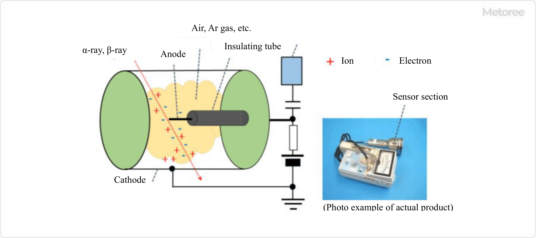
Figure 1. Basic structure and measurement principle of a GM-tube survey meter

An ionization chamber detector has the same structure as a GM-tube survey meter, with the detector filled with air or argon. When radiation strikes the detector, the air is ionized into cations and electrons, and the ionization chamber survey meter displays the minute current that flows between the electrodes. Ionization chamber survey meters are suitable for measuring β- and γ-rays and low-energy X-rays, and can measure effective dose rates in the range of 1 μSv/h to 5 Sv/h, depending on the model.

2. Scintillation by Excitation

2489_Survey-Meters_サーベイメーター-2.png

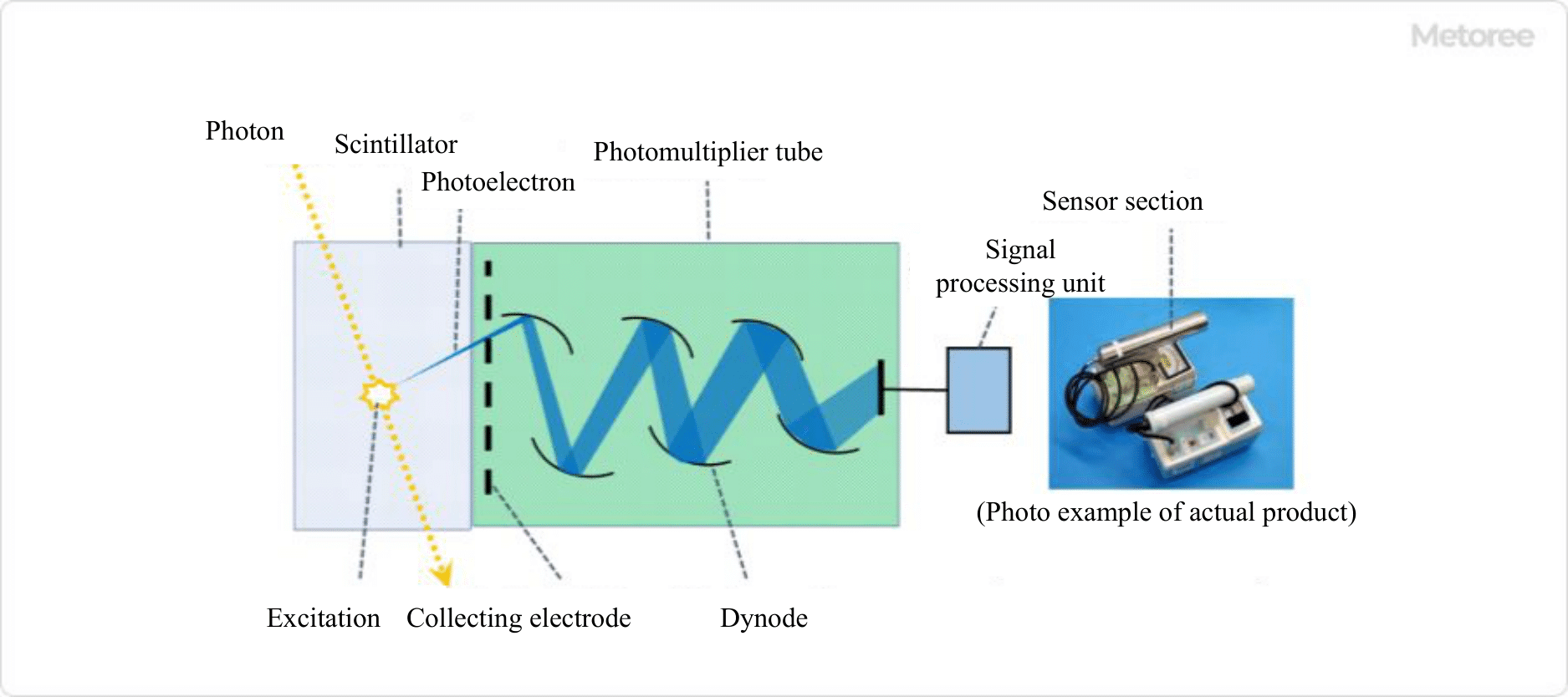
Figure 2. Basic structure and measurement principle of a scintillation survey meter

A scintillation survey meter consists of a scintillator and a photomultiplier tube as shown in Figure 2. When radiation strikes the scintillator, the crystalline material of the scintillator is excited by the photoelectric effect and other effects.

The photomultiplier tube converts the faint light generated when the scintillator returns to the ground state into an electric current, amplifies it, and counts the resulting pulsed current. Scintillators for γ (X) rays are highly sensitive and suitable for low-level radiation measurements in general environments.

3. Detection of Neutrons by Nuclear Reaction

2489_Survey-Meters_サーベイメーター-3.png

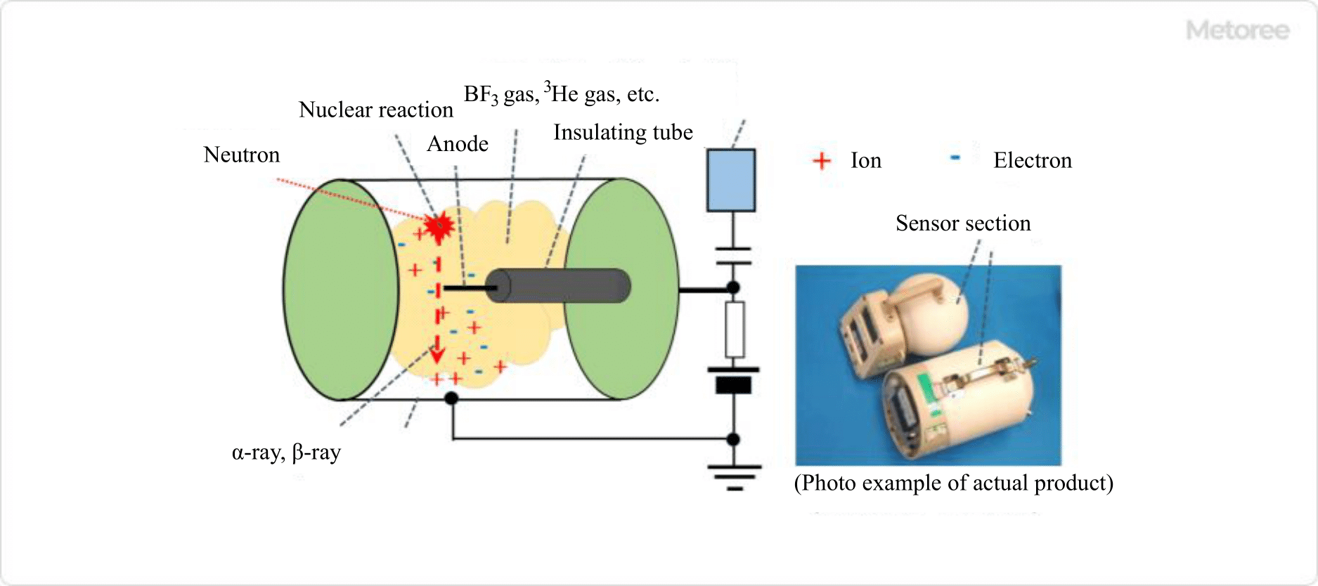
Figure 3. Basic structure and principle of a survey meter for neutrons

As a neutron survey meter, BF3 or 3He gas is filled into a detector consisting of a cathode and anode as shown in Figure 3, and α-rays and protons (p) produced by the nuclear reaction of 10B(n,α)9Li and 3He(n,p)3H are measured using the same principle as in an ionization chamber. Neutron energy ranges from thermal neutrons (0.025eV) to fast neutrons (10MeV). The effective dose rate is considered to be in the range of 0.01 μSv/h to 0.01 mSv/h.

Some detectors are spherical, usually called Bonner balls. By using multiple spheres of different sizes, the neutron energy spectrum (intensity distribution) can be obtained.

4. Personal Radiation Dosimeter

Integral dosimeters, such as film badges and TLD dosimeters, are used as personal radiation dosimeters. Film badges are based on the photosensitivity of photographic film to radiation and consist of a plastic case containing various filters and a small piece of film.

TLD dosimeters utilize the fluorescent properties of certain crystalline materials, such as CaSO4, which emit fluorescence in response to the amount of radiation received.

Other Information on Survey Meter

1. Radiation Units

  • Gy (Gray)
    A unit of absorbed dose. 1 Gy is equal to 1 kg of a substance absorbing 1 J (joule) of energy.
  • Sv (Sievert)
    A unit of equivalent dose or effective dose. Equivalent dose is the dose absorbed by each organ of the human body multiplied by the weight of each type of radiation (radiation weighting factor). The effective dose is the sum of the equivalent dose for each organ multiplied by the organ sensitivity weights (tissue weighting factors) for all organs. When referring to radiation dose, effective dose is generally used.
  • Bq (Becquerel)
    The unit of measurement for the amount of radioisotopes. When a radioisotope decays once per second, that is 1 Bq.

2. Radiation Exposure Control for Radiation Workers

Radiation workers are required to ensure that their radiation dose does not exceed 100 mSv for five years and 50 mSv for one year. For women and pregnant women, lower limits are set by law. For the general public, the standard is 1 mSv or less per year of effective dose.

To obtain correct measurement results in environmental monitoring, periodic calibration (correction of deviations in indicated values), daily inspections, and bag-ground measurements should be performed to provide a guide in case of abnormalities or malfunctions. Cases of accidents involving radiation workers leading to serious fatalities have been reported in many countries around the world. Accidents at nuclear facilities and other facilities are caused by structural defects and deviations from worker procedures, and there is a need for safety management of facilities and adherence to worker procedures.

3. Radiation Facilities

High-energy ion accelerators used for particle physics research can also be used as a high-energy neutron source by injecting protons into targets such as W (tungsten) or Li (lithium). LINAC (linear electron accelerator), etc., are used for tire hardening and treatment.

Alpha-ray sources such as 241Am (americium) are used to evaluate alpha-ray soft errors (reversal of 1, 0 data) in semiconductor devices. γ-ray irradiation equipment using 60Co (cobalt), which is used for sterilization, prevention of potato germination, and various irradiation effect studies, requires radiation exposure control for workers and researchers.

The above research and testing facilities are usually classified as “controlled areas” under the “Law Concerning Regulation of Radioactive Isotopes, etc.”, and radiation exposure and surface contamination of objects, workers, and researchers, as well as the carrying in and out of radioisotopes, are strictly controlled.

4. Nuclear Fuel Handling Facilities

Low-energy neutrons are used in experimental reactors such as those at Kyoto University, MIT (Massachusetts Institute of Technology), and the Halden reactor in Norway to treat brain tumors. In this process, living organisms and surrounding equipment may be activated.

On the other hand, commercial nuclear reactors in normal operation are required to have a periodic inspection of the reactor building and equipment approximately once a year. During the inspection, the reactor is shut down and there are no neutron rays. On the other hand, in an operating reactor core, radioactive isotopes such as 60Co are produced by the activation of structural materials and other materials.

Radioactive materials dissolve in the reactor coolant and are absorbed by the inner surface of the reactor cooling system piping, causing external radiation exposure to workers. When disassembling and repairing equipment, surface contamination must also be taken into consideration, so a survey meter is a must-have item during work.

カテゴリー
category_usa

Servo Amplifiers

What Is a Servo Drive?

Servo AmplifiersA Servo Drive is a amplifier device that controls a servo motor. A servo motor is a motor with a built-in encoder that detects the angle of rotation. The encoder feeds back displacement to the servo drive.

The control by the servo drive and the high-accuracy rotational movement of the servo motor enable the FA equipment of various manufacturers to achieve advanced drive control.

Servo drives are also called servo amplifiers, depending on the manufacturer.

Uses of Servo Drives

Servo Drives are widely used in FA equipment to drive servo motors. They are widely used in a wide range of manufacturing processes for transportation equipment, industrial equipment, electronic components, plastic parts, etc.

The following are examples of industrial applications:

  • Control of servo motors used in press equipment to drive large automotive dies
  • Control of servo motors used to drive amusement equipment (roller coasters, sliders, etc.)
  • Control of servo motors used to drive machine tools and cooperative robots
  • Control of loading/unloading machines in automated warehouses

As for home appliances, they may be used in robot vacuum cleaners, etc.

Principle of Servo Drives

The basic principle of Servo Drives is similar to that of an inverter. First, the AC power received is converted to DC. PWM control is often used.

The biggest difference from an inverter is that it receives the displacement of a paired servo motor. Most servomotors, except for large-capacity ones, are permanent magnet synchronous motors. The current flowing in the stator coil is transformed into a magnetic field, which rotates a rotor with permanent magnets.

Servo motors are equipped with an encoder that feeds back the angle and speed of rotation of the motor to the servo drive. Upon receiving the motor position information, the servo drive controls the motor in real time and stops it at a predetermined position. Control methods are broadly classified into two types: “open-loop control” and “closed-loop control”. The servo drive is a device that uses closed-loop control.

1. Open Loop Control

Open-loop control refers to control in which there is no feedback loop and the control is open to the response of the command value. As a typical example, a stepping motor is a motor that can be controlled without feedback of the actual rotation angle and speed signal of the rotor.

2. Closed-Loop Control

Closed loop is a type of control method with feedback. The output signal from the control unit feeds back data such as the travel of the machine to be controlled to the control unit, which constantly compares the input and output values and adjusts the overall operating volume to match the two.

Since there are a variety of servo drives available from different manufacturers, it is necessary to select the right type of servo drive and servo motor as a set according to the operating environment and equipment specification requirements.

Other Information on Servo Drives

Origin of Servo Drives

Servo Drives have a concept of origin. The origin is the displacement point at which the rotation angle of the servo motor becomes zero. Based on the origin, the servo motor’s displacement distance and rotation angle are calculated and output. Servo Drives may set the origin as an absolute position or may determine the origin on a case-by-case basis.

In the case of the absolute position, the servo drive remembers the origin position of the servo motor internally even when the power is turned off. The servo drive will operate as before when the power is turned back on, thus saving the time and effort of re-setting the origin. However, if the load slips against the motor shaft or if the motor is replaced, the origin will be out of alignment, so it is necessary to set the origin again.

If the origin is re-set each time, the origin must always be found and set before the machine is operated. While a preliminary operation is required before operation, the origin can be easily set when replacing parts.

カテゴリー
category_usa

Silica Sand

What Is Silica Sand?

Silica SandSilica Sand is a quartz grain.

It is characterized by its hardness, high refractoriness, and excellent chemical and acid resistance.

Uses of Silica Sand

Silica sand is used in a variety of fields, including construction and processing.

1. Construction

  • Construction materials: Mortar aggregates
  • Pavement: joints, interlocking, etc.
  • Landscaping: Aggregates for soil improvement, aesthetic aggregates, sanitized sand, etc.
  • Molding: Aggregates for concrete molding
  • Aggregates for casting
  • Glass materials

2. Other Fields

  • Aggregates for sandblasting
  • Water and sewage filtration
  • For fluidized beds in cleaning plants
  • For roofing
  • For paints and coatings
  • Joint soil for golf course
  • For bunkers
  • Principle of Silica Sand

Silica sand is made by rinsing, drying, and classifying quartz grains. These quartz grains are mined from silica stone formations, and the quartz grains are crushed into a granular form. Silica rock formations are formed when acidic rocks such as granite and quartz mottled rock are weathered and disintegrated over a long period of time and transported to and accumulated in rivers and oceans as chemically stable and weather-resistant quartz particles.

Silica sand therefore reflects the characteristics of quartz. It is characterized by its hardness and refractoriness with a high melting point of about 1,680℃. It also has excellent chemical resistance, acid resistance, alkali resistance, weather resistance and abrasion resistance.

Other Information on Silica Sand

1. Characteristics of Silica Sand by Application

Silica sand is used in a variety of fields, but care must be taken when using it as a raw material for glass or as an aggregate for casting.

When used as a raw material for glass, the SiO2 content should be 99.5% or higher. Silica sand contains minerals such as Fe2O3, FeO, Al2O3, CaO, MgO, TiO2, K2O, and Na2O in addition to quartz (SiO2). When used as a raw material for glass, iron causes coloration and reduced light transmittance, so the Fe2O3 content must be regulated.

When used as aggregate for casting, the presence of feldspar or mica can cause problems in baking and other processes. In addition to SiO2, the quality standard for castings specifies the content of Al2O3, CaO, and MgO. In addition, the moisture content of silica sand for casting must also be taken into account. 

2. Toxicity of Silica Sand

Silica sand is known to have little effect on the human body when ingested orally. However, inhalation of fine particles of silica sand through the nose or mouth can cause serious symptoms. Inhalation of crystalline silica such as quartz is a cause of silicosis. Collectively, symptoms such as silicosis and asbestos lung caused by inhalation of asbestos are referred to as pneumoconiosis.

Symptoms of pneumoconiosis tend to be subjective at first, but over time symptoms such as cough, phlegm, and even shortness of breath or difficulty breathing may appear. Once pneumoconiosis is contracted, there is no treatment and the lungs never return to normal.

Silica sand is conventionally used in sandblasting, which is a surface finishing process in which sand or other material is blown onto the surface of a material. The impact of the sand blasting causes the silica sand to become finer and more airborne, causing workers to inhale the fine particles of silica sand, which can lead to the development of silicosis.

Therefore, in recent years, silica sand with reduced silica content has been developed for sandblasting and is widely used. To prevent such accidents, the use of protective equipment such as dust masks is usually recommended.

カテゴリー
category_usa

Silicone Tubing

What Is Silicone Tubing?

Silicone Tubing

Silicone tubing is a tubular product made primarily of silicone rubber. They are commercially available in a variety of lengths and diameters and can be used flexibly according to the purpose and application.

Silicone rubber, also known as silicon rubber, is a type of organic silicon compound polymer. Its main backbone is siloxane bonds (-Si-O-Si-), which have high bonding energy.

It has excellent heat resistance, chemical resistance, and electrical insulation properties. These properties are used to transport chemicals and for protective covers.

The Difference Between Silicon and Silicone

The term silicon refers to the element silicon itself. On the other hand, silicone is a polymer of organosilicon compounds, such as silicone rubber, silicone resin, and silicone oil.

In other words, these two compounds are completely different and should be treated with caution. However, these two terms are often used interchangeably, and the usage of “silicone tube” applies to this as well.

Uses for Silicone Tubing

Silicone tubing has excellent chemical resistance and is used to transfer chemicals, fuels, and other materials that would otherwise corrode with plastics.

They are also frequently used in research and development, quality control, analysis, and testing, where a variety of chemicals must be used.

Silicone tubing also has an excellent heat resistance and is used in hoses for hot water heaters and bathtubs.

They also have electrical insulating properties and are used for insulation and protective covering applications for home appliances and electric wires.

Principles of Silicone Tubing

Silicone tubing is a tubular product made of silicone rubber.

Silicon, a non-metallic element with atomic number 14 and element symbol Si, is one of the most abundant elements in the earth’s crust.

Generally, silicone rubber is made from highly polymerized dimethylpolysiloxane, an organosilicon compound.

The siloxane bond (-Si-O-Si-) is the main structure, with substituents such as methyl groups attached to the side chains.

The siloxane bond has a higher bond energy than other bonds, such as C-C bonds, and is therefore chemically more stable than ordinary organic polymers, which is reflected in properties such as heat resistance.

Silicone tubing has excellent heat resistance, chemical resistance, oil resistance, water resistance, electrical insulation, and weather resistance. Since they are resistant to chemical reactions with other substances, they are used as tubes for pumping chemicals and analyzers.

It is also tasteless, odorless, and safe, so it can be used as food transport tubing. Since it is also heat resistant, it can be used for packing and protective covers for areas subject to high temperatures, but it deteriorates and breaks when exposed to excessively high temperatures.

カテゴリー
category_usa

Silicone Resin

What Is Silicone Resin?

Silicone Resins

Silicone resins are resins whose main backbone is a siloxane bond (Si-O-Si) composed of silicon and oxygen and are also commonly referred to as silicone. Organic groups are introduced into the side chains, and silicone resins exhibit both inorganic and organic properties. They also exhibit various physical properties depending on the type of functional group in the side chain.
Siloxane bonds have higher bonding energy than the carbon-carbon bonds that form the main chain of plastics, so silicone resins have better heat resistance, weather resistance, and electrical insulation properties than general plastics.

Silicone resin is classified into silicon oil and silicon rubber. In the case of liquid silicone resin, injection molding, and extrusion molding are used to mold it as a product. Recently, 3D printers have also been used for molding.

Uses of Silicone Resin

Silicone resin is a resin consisting of silicon and oxygen repeatedly bonded together. It is used as silicone oil or silicone rubber, taking advantage of its various advantages such as heat resistance, weather resistance, and electrical insulation.
For example, it is used as a heat-transfer medium as a highly heat-resistant oil, or in industrial applications such as anti-vibration oil in environments with extreme temperature changes. It is also used in other applications such as baby bottle rubber, various gaskets, and shampoo.

In the construction field, it is also used as a protectant to prevent the deterioration of coatings and gaskets. Silicone resin is also used in various parts of vehicles.

Principles of Silicone Resin

Siloxane bonds, which are continuous silicon and oxygen bonds formed in silicone resins, belong to the same class of inorganic materials such as glass and quartz. Siloxane bonds have higher bonding energy and are chemically more stable than carbon-carbon bonds, which are the main type of bonds in organic materials. This is one of the reasons why silicone resins have high heat and weather resistance.

Siloxane bonds exhibit inorganic properties, whereas silicone resin also has organic functional groups such as carbon in the side chain, so it exhibits both inorganic and organic properties. In addition, various organic functional groups such as methyl groups, alkoxy groups, and amino groups can be introduced into the side chain, and different properties can be expressed depending on the functional group. For example, silicone resin with three or more oxygen groups bonded to silicon exhibits a three-dimensional network structure and exhibits particularly excellent heat resistance and weather resistance.

Difference Between Silicone Resin and Plastic

Although silicone resins are highly processable and have characteristics similar to plastics, such as softening upon heating, they are chemically different substances. Silicon resins contain a large number of silicon atoms in their main backbone, whereas plastics such as epoxy resins have the main chain backbone composed primarily of carbon atoms.

Compared to the carbon-carbon bonds in the main skeleton of plastics, the bonding energy of the silicon-oxygen bonds in the main skeleton of silicone resins is higher and less reactive, so they generally have better chemical and heat resistance than plastics. For this reason, silicone resins are widely used in daily necessities, kitchenware, and industrial products. However, care must be taken when using chemicals, as contact with strong acids and alkalis can cause decomposition and degradation.

Safety of Silicone Resin

Silicone resin has extremely low physiological activity and is considered to have virtually no effect on the human body. It also has low health effects even if ingested orally, and studies on acute toxicity and genotoxicity have been reported to be negative.

Silicone resin is used in tableware and cooking utensils, etc. It is an extremely stable resin and does not react with food even in high-temperature environments during cooking. However, if the temperature reaches an abnormally high level due to overheating or emptying, the silicone resin may melt or discolor, so care must be taken when using it at high temperatures.

On the other hand, silicone resin contained in sprays is a very small particle that can cause respiratory poisoning if inhaled. Even when using household products such as water-repellent sprays, care must be taken in handling them, such as using them in a well-ventilated area and not using them directly on the human body. In addition, instructions and Safety Data Sheets (SDS) should be carefully read before use.

カテゴリー
category_usa

Silicone Mold Release Agent

What Is a Silicone Mold Release Agent?

Silicone Mold Release Agents

A Silicone mold release agent is a chemical that allows products to be removed smoothly from molds during the molding process.

By applying silicone mold release agent to the mold, the product is prevented from sticking to the mold and can be molded beautifully without damaging the surface of the product. As the name suggests, silicone is used as the main ingredient.

Its low surface tension and ease of spreading make it easy to apply to any mold. Furthermore, it is chemically inert and can be used on almost any material. Their very low intermolecular forces and incompatibility with most molding materials make them excellent mold release agents.

Uses of Silicone Mold Release Agents

Silicone mold release agents are used in a variety of molding processes. They are useful for molding products made of various materials, such as plastic, rubber, and metal. For example, silicone mold release agents are used to cleanly mold plastic models, toys, car parts, kitchenware, and many other products found in our daily lives. Silicone mold release agents are also used in the food industry for molding food packaging and containers.

Other applications include die casting, surface treatment, and synthetic fibers. Silicone mold release agents can also be used for purposes other than improving mold release properties, as they also have functions such as glazing, surface protection, and lubrication. They are generally used in emulsion, oil, or solution form, but can also be baked or sprayed on.

Principle of Silicone Mold Release Agents

Silicones combine the properties of inorganic compounds based on Si-O bonds with those of compounds derived from organic groups such as methyl groups (-CH3) attached to Si atoms.

1. Mold-Releasing Properties

Silicones have low surface energy and low intermolecular forces because their surfaces are covered with organic groups. This means that they are less likely to stick to other substances and more likely to peel off. This property makes it possible to improve mold release properties.

When intermolecular forces are extremely low, cohesion is weak and diffusion is easy. Silicone can be spread thinly over the mold surface without becoming droplets. This results in the formation of an extremely thin silicone layer on the surface of the silicone mold release agent when it is applied to the mold. This silicone layer prevents direct contact between the product and the mold and facilitates demolding.

2. Heat Resistance

Silicone has high heat resistance and does not lose its functionality even at high temperatures. This is because the bond between silicon and oxygen, the main chain of silicone, is more stable than the bond between carbon and carbon. Therefore, silicone can be used in molds for plastics that are molded at high temperatures.

Although silicone may migrate to the surface of the molded product after demolding, it can be used for a long time by baking a silicone mold release agent into the mold to form a film.

Types of Silicone Mold Release Agents

1. Emulsion Type

An emulsion that has emulsified silicone oil, and it excels in dilution stability. They are used for food packaging containers, as release agents for rubber and plastic molding, ironing lubricants, and luster release agents.

2. Oil Type

It has excellent heat resistance and wettability, and is chemically inert. It is excellent for mold release and glazing in rubber, plastic and tire molding. It is also used as a base oil for other silicone mold release agents.

3. Solvent Type

Silicone resins are diluted with solvents such as toluene or other petroleum hydrocarbons. They have excellent wettability on molds. The solvent volatilizes easily, making heat treatment easy. When baked on, it forms a film that provides a long-lasting mold release effect and prevents transfer of the mold release agent to the product.

How to Choose a Silicone Mold Release Agent

This section explains how to select a silicone mold release agent. There are three main points to consider when selecting a silicone mold release agent.

1. Mold Release Performance

Whether or not a product can be demolded smoothly depends largely on the performance of the mold release agent. The appropriate mold release agent depends on the shape and material of the product, so it should be selected according to the purpose.

2. Heat Resistance

Select a mold release agent that can withstand molding temperatures. The required heat resistance varies depending on the material and molding method of the product to be molded.

3. Safety

It is important to select a mold release agent that will not affect the human body, especially when molding food or medical products.

カテゴリー
category_usa

Syringe Filters

What Is a Syringe Filter?

Syringe Filters

Figure 1. Syringe filter

A Syringe Filter is a disk-type filter that is attached to the end of a syringe.

It is used to remove particulate impurities from a liquid sample. When a syringe filter is attached to the tip of a syringe, the solution passes through the filter as it is pushed out, and insoluble matter is removed.

The filter part is made of PTFE (polytetrafluoroethylene) or PVDF (polyvinylidene fluoride). The material is selected based on the characteristics of the solvent and the target material to be removed. Since there are a variety of pore sizes, the most appropriate filter should be selected according to the size of the particles to be removed.

Syringe Filters are usually used on a disposable basis.

Uses of Syringe Filters

The main applications of syringe filters include sample purification and pretreatment of various analytical samples. Major analytical methods include HPLC, ion chromatography, gas chromatography, ICP, and dissolution testing. They are also used in general filtration to remove fine impurities in aqueous solutions and organic solvents.

Another application is sterilization, where bacteria smaller than the pore size of the filter are removed by filtration. In this case, an appropriate sterilization filter must be used.

Syringe filters themselves, like membrane filters, are not very large and can only capture particles on their surface. If there is a large amount of insoluble material, another pretreatment should be performed beforehand to remove most of the insoluble material.

Principle of Syringe Filter

2520_Syringe-Filters_シリンジフィルタ-2.png

Figure 2. How a syringe filter works

A syringe filter consists of a disc-shaped filter in a plastic case. The plastic case has a protrusion with a hole at each end. When a syringe is attached to one end and the plunger of the syringe is depressed, the solution flows through the filter and out the other protrusion. As the solution passes through the filter, particles larger than the filter’s pore size are intercepted and insoluble material is removed.

Filters are available in a variety of pore sizes. Particles larger than the maximum pore size listed on the product can be trapped on the surface of the filter. On the other hand, the pores can become clogged by large amounts of insoluble matter, so it is necessary to use an appropriate filter after confirming the type, amount, and particle size of the insoluble matter.

Types of Syringe Filters

Syringe Filters can be classified in terms of material, sterility, and pore size.

1. Material

Typical Syringe Filters are made of the following materials

  • PTFE (Polytetrafluoroethylene)
  • PVDF (Polyvinylidene Fluoride)
  • PES (Polyethersulfone)

PTFE and PVDF are hydrophobic materials, but some products can be applied to a wide range of polar and non-polar solvents by hydrophilizing the surface.

2. Sterilization/Non-Sterilization

Syringe filters can be sterilized or non-sterilized. Non-sterile syringe filters are used for general filtration and sample purification.

Sterile syringe filters, on the other hand, are used to sterilize solutions or to clarify sterile solutions. Since common bacteria are 1-5 μm in size, a filter with a pore size of 0.22 μm is sufficient for filtration and sterilization.

However, some bacteria of the genus mycoplasma have a size of about 0.2 μm. For the purpose of removal of bacteria of the genus mycoplasma, it is necessary to select a filter pore size of 0.1μm. Bacteria of the genus mycoplasma parasitize eukaryotic cells and affect cell culture. Therefore, it must be kept in mind in cell culture experiments where mycoplasma negativity is essential.

3. Pore Size

2520_Syringe-Filters_シリンジフィルタ-3.png

Figure 3. Differences in removed particle size

The pore sizes and applications of syringe filters are mainly as follows:

  • 0.1 μm: removal of mycoplasma
    Used for mycoplasma removal from reagents and culture media. Since mycoplasma spp. are parasites of eukaryotes, mycoplasma-negative cells are a prerequisite for tests using cells. This type of filter should be used because mycoplasma spp. with cell size of about 0.2-0.3 μm, which have no cell walls and are irregularly shaped, can pass through a general sterilization filter (pore size 0.22 μm).
  • 0.22μm: Sample pretreatment/Filtration sterilization
    This filter is used for sample pretreatment for analytical instruments that use fine packing materials such as UPLC. Sterilization filters are used for sterilization applications.
  • 0.45 μm: Sample preparation for analysis
    Used for general sample preparation such as HPLC samples.
  • 0.8 μm: Particle removal
    Used to remove relatively large foreign particles such as ampoule fragments in drugs.