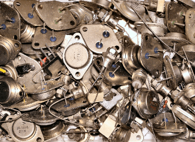
What Is a Power Transistor?
 A Power Transistor is a transistor with an allowable power of 1W or more in operation. They are used in electrical devices that are driven by large currents.
The main roles of power transistors are current amplification, switching, and rectification of alternating current.
Because of the large currents they handle, they generate a lot of heat during operation, and so products have heat-resistant metal cases or fins for heat dissipation.
There are several types of power transistor, with bipolar power transistors, MOSFETs, and IGBTs being the most common.
Uses of Power Transistors
Power transistors are used for applications such as switching and current amplification in electrical equipment that requires a large current to operate. Typical applications include home appliances such as air conditioners, refrigerators, and washing machines, solar power generation, and electric vehicles.
Depending on the application, the allowable current, voltage, heat generated during operation, size, and other factors must be considered. If the destination is a product that needs to operate with high precision, the switching speed and other factors should also be taken into consideration to switch the current flowing through the circuit and amplify the current.
Principle of Power Transistor
The principle for the operation of power transistors varies depending on the type.
1. Bipolar Transistor
A bipolar transistor is a transistor with a structure consisting of three layers of N-type and P-type semiconductors joined together.
The semiconductors that make up the bipolar transistor have terminals coming out of each semiconductor, which are called the base, emitter, and collector. With voltage applied to the emitter and collector, a large current flows between the emitter and collector when current flows in the base.
2. MOSFET
A MOSFET is a transistor with a structure similar to a bipolar transistor. The terminals are named source, drain, and gate. When voltage is applied to the gate, current flows between the source and drain.
Because of its high-speed switching capability, this transistor is used in products that require quick control.
3. IGBT
An IGBT is a transistor with the same structure as the above two transistors. The terminals are called gate, emitter, and collector. The structure is a combination of the emitter and collector from a bipolar transistor and the gate adopted from a MOSFET.
This type of transistor has the good points of the above two transistors and has a wide range of applications.
Types of Power Transistors
There are two main types of power transistor: bipolar transistors and field-effect transistors.
1. Bipolar Transistor
A bipolar transistor is a current control device. There are NPN and PNP types depending on how the semiconductors are stacked. They generally have three terminals, two paths for the output current and one input that controls the output current.
An emitter-grounded circuit is typically used, with the input signal at the base (B), the + supply at the collector (C), and the emitter (E) grounded. The DC current amplification factor of a bipolar transistor is expressed as β or hFE and ranges from tens to 200.
Power transistors with Darlington configuration are also available to earn β (β is in the hundreds to thousands).
2. Field Effect Transistor
Field-effect transistors, on the other hand, are voltage-controlled devices and come in N- or P-channel structures.
They typically have three terminals, two paths for the output voltage and one input that controls the output voltage. A source-ground circuit is typically used, with the input signal on the gate (G), the + supply on the drain (D), and the source (S) grounded.
The DC voltage amplification factor of an electrolytic effect transistor is expressed in terms of mutual conductance (gm). They have better switching characteristics than power transistors and are often used in switching power supplies.
Other Information on Power Transistors
Identification of NPN and PNP Transistors
If a transistor, which is often used in output and power supply sections, fails, the output of the circuit may be lost or become unstable. Therefore, it is important to check for transistor failure.
1. NPN transistor
For NPN transistors (2SC or 2SD), check the following:
- Base (B) positive, continuity to collector (C) and no continuity in the reverse direction
- Base (B) positive, continuity to emitter (E), not reversed
- Collector (C)-emitter (E) is disconnected in either direction
If all three of these are true, the transistor is okay.
2. PNP Transistor
In the case of a PNP transistor (2SA or 2SB), the reverse direction is true.
- Collector (C) positive, conducts to base (B), not opposite direction
- Emitter (E) positive, conducts to base (B), not in reverse
- Collector (C)-emitter (E) conductive in either direction, non-conductive in the reverse direction
If all three of these conditions are satisfied, the transistor is okay.
Note: this test cannot be used for Darlington transistors.
When the tester is used in the continuity range, the red side is negative and the black side is positive. Pay attention to the polarity of the test voltage on the tester leads. Also, be sure to disconnect the power supply, input wires, output wires, etc. of the non-test object before testing.