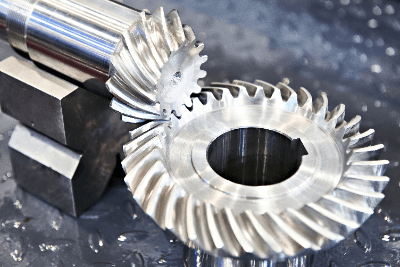
What Are Bevel Gears?
 Bevel Gears are gears with teeth carved on a conical surface, and each axis is angled rather than parallel. They are used to transmit power by changing the direction of the axis of rotation.
Bevel Gears are named as such because they look like umbrellas. They are classified into straight bevel gears, spiral bevel gears, helical bevel gears, zerol bevel gears and hypoid gears according to the tooth shape.
Materials used for bevel gears include carbon steel for machine structural purposes, alloy steel for machine structural purposes, rolled steel for general structural purposes, cast iron, stainless steel, nonferrous metals, MC nylon and duracon.
Uses of Bevel Gears
Bevel gears are used to transmit power by changing the direction of a rotating shaft. In bevel gears using straight, spiral, and helical gears, the axes of rotation of the two gears intersect. The angle of intersection is generally 90°, but may be acute or obtuse. Gears whose axes do not intersect are called hypoid gears.
Familiar examples are hand-turned coffee mills, hand-turned mixers, and hand drills. They are also used in differential gears in the automotive field, as well as in machine tools and printing machinery. They are especially useful in differential equipment.
Hypoid gears differ from spiral bevel gears in that multiple teeth engage simultaneously and there is tooth slippage. This allows them to withstand large torques and to produce little noise. Hypoid gears are often used to drive automobiles and trains.
Principle of Bevel Gears
Bevel gears are gears with pitch conical surfaces that contact each other without sliding. Gears are determined by module, number of teeth, reduction ratio, material, surface treatment, shaft hole shape, shaft hole diameter, and precision.
Straight bevel gears have a straight tooth trace and are relatively easy to manufacture. Reduction ratios of up to about 1:5 are possible. If no specific gear is specified, they are generally used as bevel gears for transmitting power.
Spiral bevel gears are characterized by the curved tooth trace. They have the advantages of high strength, quiet rotation, and high efficiency due to the large area per tooth. Zerol bevel gears are spiral bevel gears with a cross-torsion of approximately zero on the shaft, and have the characteristics of both immediate and spiral bevel gears.
Gears can accurately transmit power and motion, but in principle, they generate noise. To reduce noise, it is necessary to take measures such as proper backlash, increasing the gear meshing ratio, downsizing the tooth profile, using plastic gears, and proper lubrication.
To improve tooth contact, an appropriate bulge may be added in the direction of the tooth flanks. This is called crowning.
How to Select Bevel Gears
When selecting bevel gears, special consideration should be given to tooth strength and allowable tooth surface load. The bending strength of a tooth is the allowable circumferential force of the tooth calculated from the strength of the tooth base during mesh transmission. It increases with increasing tooth module size.
The allowable tooth surface load is the circumferential force specified to prevent progressive pitting. The smaller of the two circumferential forces is multiplied by the pitch circle radius of the gear to obtain the allowable torque of the gear. This value should be selected so that it is greater than the design torque actually used. The characteristics of each gear are described in the manufacturer’s technical data.
Some manufacturers also provide a list of gears that meet their requirements by entering the conditions of use on their website. This is useful when narrowing down specifications from broad conditions.
Other Information on Bevel Gears
Bevel Gear Design
When designing bevel gears, it is important to tentatively determine the reduction ratio and shaft angle and check the gear specifications because, unlike spur gears, there are limitations on the combination of the number of teeth on the meshing gears and the dimensions such as the bevel angle are different.
After tentatively determining the shape and mounting posture, strength calculations are performed. If the conditions are not satisfied, the module is enlarged and the dimensional calculations are redone again. Gear strength and other meshing calculations can be approximated with spur gears.
When the load is large, when repeated loads are applied, or when the gear is operated continuously for a long period of time, a large safety factor can be used to provide a margin against impact loads and fatigue.
For material selection, carbon steel is generally used and its surface hardness is increased by quenching, but for some applications, alloy steel or other materials are used and their hardness is increased by quenching. Generally, only the tooth flanks are quenched by high-frequency induction hardening, while other parts are tempered.
In addition to calculating dimensions and strength, lubrication must also be considered in gear design. Lubrication and lubrication systems are determined and designed for easy maintenance.